Table of Contents
Advertisement
(1) Introduction & accessories
Thank you for purchasing the new AOR AR2700 wide band receiver.
This operating manual is divided into many sections and presented in a logical
order assuming that it will be read section by section following the examples.
However, if you are familiar with the operations of modern multi-function
receivers you may proceed directly to section 6. Many phrases are
repeated through the manual, while this may make the text a little repetitious, it
should provide clear instructions if you refer directly to a specific section.
Every effort has been made to make this manual correct and up to date. Due
to continuous development of the receiver and by error or omissions,
anomalies may be found and this is acknowledged.
Most apparent faults are usually due to accidental misoperation of the receiver,
carefully read all of the manual before deciding to return the receiver for repair.
Although carefully designed, this receiver (like all receivers) suffers from a
degree of internal noises known as spurii. They are a product of the receiver's
circuitry and do not represent a fault.
This manual is protected by copyright AOR LTD 1995. No information
contained in this manual may be copied or transferred by any means without
the prior written consent of AOR LTD. AOR and the [AOR] logo are trade
marks of AOR, LTD. All other trade marks and names acknowledged. E&OE.
© 1995 AOR LTD.
Operating manual Conventions and special notes
Where text appears in [SQUARE BRACKETS] the keys are to be pressed
exactly as shown.
For example: [1] [4] [5] [ENT]
Means press the 1 key followed by the 4 key followed by the 5 key
followed by the ENTER key.
The arrow keys to the lower left of the keypad are referred to as UP / DOWN or
[UP] [DOWN] keys.
Words contained in speech marks "BANK" refer to indications displayed on the
Liquid Crystal Display.
Where memory banks etc are empty the indication "- - -" is often displayed.
[2ndF] function key: The function key [2ndF] provides access to additional
facilities via the numeric keypad. The function key should be momentarily
pressed only (so that the legend "2ndF" appears in the top left corner of the
LCD) before another numeric key is pressed... do not hold the function key
in while pressing other keys.
Advertisement
Table of Contents

Related Manuals for AOR AR2700


Summary of Contents for AOR AR2700
-
Page 1: Introduction And Accessories
This manual is protected by copyright AOR LTD 1995. No information contained in this manual may be copied or transferred by any means without the prior written consent of AOR LTD. AOR and the [AOR] logo are trade marks of AOR, LTD. All other trade marks and names acknowledged. E&OE. -
Page 2: Table Of Contents
FULL reset as all memory and search data has to be deleted... be patient as 30 seconds feels like a very long time when you are waiting. Remember also, when there is no memory or search data, the AR2700 will not scan or search until you have input new data. - Page 3 5-12 [RESET] microprocessor reset switch ....23 RIGHT HAND SIDE ..........24 5-13 DC 12V - charging and DC input socket ....24 REAR CABINET ............ 24 5-14 RS232 REMOTE connector ........25 5-15 Battery compartment ..........25 Basic manual operation of the receiver .....
-
Page 4: Major Features
............63 (3) Major features General The AR2700 is a new generation of receiver combining a wide frequency coverage with advanced features and facilities. Internal construction is of a high quality modular surface mount design. This ensures the highest levels of performance and reliability. - Page 5 Memories and search banks A total of 500 memory channels are provided which are divided into 10 banks, each having 50 channels. The AR2700 will search and scan at a very respectable (and fast) maximum speed of approximately 30 increments per second.
-
Page 6: Precautions
The connector is CENTRE POSITIVE (which is the RED terminal of most DC power supplies). The outer connector is NEGATIVE - ground. Should you be using the AR2700 at home with an external aerial, a separate earth connection may be made between the outer earth connector of the BNC... -
Page 7: Nicads And Charging
Always disconnect the charger from the AC mains supply when not in use. If using dry batteries (Alkaline or Manganese), always remove the batteries when exhausted or if the AR2700 is not going to be used for a while. This will avoid leakage which could seriously damage the receiver. -
Page 8: Aerial (Antenna) Connection
Of course, except for government listening stations this is totally impractical. For this reason most people choose an externally mounted discone aerial such as the AOR DA3000 aerial. The DA3000 has a usable frequency coverage of 25 to 2000 MHz. -
Page 9: Controls And Functions
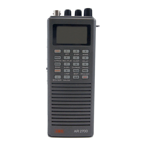
The circuitry offers a small level of gain with the advantage of selectivity similar to an ATU. (5) Controls and functions The AR2700 receiver is housed in an attractive and modern looking grey plastic cabinet. Controls for operation are located on the top, front and left hand side of the cabinet. -
Page 10: Aerial (Antenna) Input
The squelch control is used to eliminate unwanted background noise when monitoring a normally inactive frequency and is used by the AR2700 microprocessor to determine when a channel is “active” (busy). The receiver cannot scan or search when the background noise is present. -
Page 11: Volume Control
On until the set fully powers up. Not all legends are used by the AR2700. To remove the test pattern, briefly press the [PWR] key again. Attractive green rear illumination of the LCD (and keypad) is switchable for use in locations of low level lighting. - Page 12 and other operational data in conjunction with the left side panel [2ndF] function key and top panel [DIAL]. If a key is not pressed within about 30 seconds during data entry, the entry will be aborted and the receiver will return to the previous display. Attractive green rear illumination of the front keypad and LCD is switchable for use in locations of low level lighting.
- Page 13 When correctly activated and BEEP enabled, a high pitch bleep will confirm operation. To switch the receiver Off simply press and hold the key again for more than 1.5 seconds. If the BEEP is enabled and you press the key for too short a period, a low pitch beep advises of the error.
- Page 14 [SCAN] [BANK] - scan / memory recall / search bank preview key When the [SCAN] key is pressed briefly, the receiver enters MEMORY RECALL mode, the display legend “BANK” appears on the top left of LCD along with bank and channel number. The receiver monitors whatever frequency is displayed on the LCD.
- Page 15 SEARCH, SCAN or MANUAL operational modes. [MANU] - manual mode The AR2700 receiver has a manual operational mode often referred to as VFO MODE. The term VFO historically means “Variable Frequency Oscillator” and today refers to a tunable data store which contains frequency, mode, channel step, and attenuator information.
- Page 16 [UP] key for more than 1.5 seconds while in manual mode. The key sequence [2ndF] [UP] places the receiver in ready condition to CLONE data to another AR2700 connected to an optional CU8232 via the optional IF-ADP. This facility enables an exact data copy of one receiver to be made with another possibly belonging to a friend etc.
- Page 17 The key is also used to select menu options under certain circumstances. The key may be used to place the receiver in manual search mode by pressing and holding the [DOWN] key for more than 1.5 seconds while in manual mode. The sequence [2ndF] [DOWN] places the receiver into “SS”...
- Page 18 If the sequence [2ndF] [4] is keyed, the legend “PLAY” will be displayed on the LCD and a previous 20 second digital recording may be replayed (presuming that the optional record chip has been fitted). If the optional chip has not been fitted then white noise will be heard.
- Page 19 In search, scan and memory modes this key is used to identify bank 7. If the sequence [2ndF] [7] is keyed while in memory recall mode or when stopped on a channel during scan, the displayed frequency will be deleted from the memory bank and the set will move on to the next memory channel containing data (upward or downward depending upon how programmed).
- Page 20 [0] [LAMP] Numeric 0 / Lamp key This key acts as a numeric 0 when entering frequencies via the keypad. In search, scan and memory modes this key is used to identify bank 0. If the sequence [2ndF] [0] is keyed, the LAMP will be switched on for a period of about five seconds.
- Page 21 Should you prefer, it is possible to switch “musical notes” to most of the keypad keys when the keylock is On. This may be accomplished by holding down the [4] key while switching On the receiver by the [PWR] key. The musical notes are arranged as follows: [PASS] [PRIO]...
-
Page 22: Internal Loudspeaker
The [ENT] key is also used during a FULL microprocessor reset. 5-8 Loudspeaker (internal) The AR2700 is fitted with an internal front facing loudspeaker toward the lower front cabinet. When an external earphone, headphone or speaker is connected, the internal speaker is automatically disconnected. -
Page 23: [Moni] Monitor Key
On. 5-12 RESET switch Should you experience a programming / operational problem with the AR2700, you may “soft” reset the microprocessor by momentarily pressing the reset switch located on the left hand cabinet using a pointed... -
Page 24: Right Hand Side
(such as to a vehicle 12V cigar lighter socket using the DC lead). The AR2700 may also be connected to a separate regulated DC power supply for use at home. The rating of the regulated power supply must be a nominal 12V to 13.8V DC @ 300mA or higher current... -
Page 25: Rs232 Remote Connector
An optional adaptor (IF-ADP) and interface (CU8232) is available for cloning (copying) of data between two AR2700 receivers and an RS232 lead plus software is required for computer control. -
Page 26: Basic Manual Operation Of The Receiver
to external supply. However, always switch the receiver Off when changing batteries or connecting / disconnecting external power. The receiver may switch On by itself when fitting batteries, this is quite normal. (6) Basic manual operation of the receiver Operating manual conventions Where text appears in [SQUARE BRACKETS] the keys are to be pressed exactly as shown. -
Page 27: Entering Frequencies (Using The Keypad)
If keying in a whole MHz such as 118.000 MHz there is no need to key in either the decimal point or trailing zeros, they are all added automatically by the AR2700 microprocessor. Example of “MHz round number” frequency entry for 118.000 MHz... -
Page 28: Correcting Frequency Input
PROG: If the frequency display changes when the [ENT] key is pressed, then an inappropriate step size has been selected. The AR2700 has an automatic bandplan lookup table so that an appropriate step size and mode should be selected. It is possible to override this PROGRAM data by simply selecting a different step size or mode. -
Page 29: Changing Frequency - Up / Down Keys & [Dial]
The rotary tuning [DIAL] provides the very best “user interface” with the AR2700. Rotating the [DIAL] clockwise increases frequency while rotation anti-clockwise decreases receive frequency. Being a mechanical device, it is... - Page 30 The AR2700 has been pre-programmed at the factory with all the bandplan data (specific to each market area) so that the AR2700 will automatically select the appropriate step size and mode for the frequency chosen. This greatly simplifies operation of the receiver while you are familiarising yourself with all the facilities.
-
Page 31: Changing Receive Mode (Program)
PROGRAM MODE. When “PROG” is selected, the receive mode and step size will be selected automatically using the pre-programmed AR2700 bandplan data and FM is in fact NFM (narrow FM). The currently selected mode will be flashing on the LCD to indicate that a new mode input is anticipated. -
Page 32: Attenuator
When listening in VERY strong signal locations especially when using an external aerial, the WFM I.F. amplifier may be overloaded. This will not damage the AR2700 but may result in “apparent signal loss”. Should this be encountered, use the attenuator to reduce signal strength or swap to the standard telescopic whip aerial. -
Page 33: Memory Banks & Channels
legend “ATT” is extinguished when the attenuator is Off. The selection of attenuator may also be programmed into memory channels and when defining program search. (7) Memory banks & channels It is very convenient to store commonly used frequencies into a memory bank along with mode and attenuator status, this saves having to key the data in over and over again. -
Page 34: Automatic Memory Incrementation
[MANU] to place the receiver into MANUAL mode [8] [8] [MHz] [3] [ENT] to select the desired frequency, the mode and step size will be automatically set by the AR2700 microprocessor. Press and hold the [ENT] key for more than 1.5 seconds to enter memory input mode. -
Page 35: Memory Recall
If you had previously written memory data to location “315”, then the microprocessor will automatically increment to location “316” or the first available empty memory channel. The microprocessor will always select the bank number last used unless otherwise specified. Should you wish, you may instruct the microprocessor to “offer”... -
Page 36: Transfer Of Memory Channels To Vfo
Key in the new frequency of 92.7 MHz [9] [2] [MHz] [7] [ENT] to select the desired frequency, the mode and step size will be automatically set by the AR2700 microprocessor. Now to select and over-write an existing memory location. -
Page 37: Deleting Memory Channels And Banks
“BANK” and “CH” will flash to indicate that memory input is in progress. Press [0] [0] [0] to select the memory location you wish to over-write (000), the stored frequency and new frequency data will alternately flash on the LCD. Press [ENT] to over-write memory location “000”. -
Page 38: Priority Operation
FULL reset as all data has to be deleted !!! (8) Priority operation The PRIORITY feature enables you to carry on scanning, searching or monitoring while the AR2700 checks a special frequency every five seconds (default) for activity. The priority checking is accomplished by momentarily moving to the priority frequency to see if it is “active”. -
Page 39: Activating & Deactivating Priority
For example, to set the frequency 145.500 MHz as the priority channel: First ensure that the receiver is in manual mode by checking that the legend “MANUAL” is displayed on the LCD or by pressing [MANU]. Enter the required frequency [1] [4] [5] [MHz] [5] [ENT]. -
Page 40: Scan - Scanning Memory Channels & Banks
(9) SCAN - scanning memory channels & banks The AR2700 has a SCAN mode whereby the contents stored in the MEMORY CHANNELS ARE AUTOMATICALLY RECALLED AND MONITORED very quickly for activity - scanned. * It is important that you do not confuse SCAN and SEARCH modes. *... -
Page 41: Memory Transfer To Vfo
process. Alternatively, the UP / DOWN key may take the place of the second [SCAN] key press. Secondly From “MEMORY RECALL” mode: Press [SCAN] once holding the key for more than 1.5 seconds to initiate the scan process. Alternatively, the UP / DOWN key may take the place of the [SCAN] key press. -
Page 42: Scanning A Single Memory Bank To Scan
away from the channel or listen to it indefinitely until you decide otherwise. To force the receiver to pause on a memory channel for about 30 seconds, press [2ndF] [SCAN]. To cancel the SCAN process and return to the VFO’s previous frequency without transferring the contents of the memory channel press [MANU]. -
Page 43: Scanning A Memory Bank Which Is Not Linked
Only the scan bank manually selected will be scanned. 9-7 SCAN channel PASS - CH PASS (lockout), general outline Should the AR2700 stop on an active channel while scanning and for some reason you do not wish to monitor it any longer, simply press the UP / DOWN keys or rotate the [DIAL] to force the SCAN process to resume in the direction selected. -
Page 44: Delay And Pause Facilities - Scan & Search
CHANNEL PASS status. (10) DELAY and PAUSE facility in scan and search modes Two user programmable timers are provided for optimising the AR2700 to suit certain applications. These timers are “global” and affect every scan and search mode. -
Page 45: Pause Time
passed back-and-fore between a control tower / aircraft which may take a few seconds. If you are scanning duplex channels then a small delay or no delay at all may be preferable. The limits are 0.0 to 9.9 seconds with 0.0 being interpreted as DELAY OFF. The default is 2.0 seconds. -
Page 46: Search
(11) SEARCH - manual & program search banks and PASS The AR2700 has a SEARCH mode whereby an upper and lower frequency limit may be defined and the receiver instructed to look for activity on all frequencies in selected step size and mode in an upward or downward direction. - Page 47 AR2700 during manufacture. Example of manual search For example, to search manually from 145.000 MHz key [1] [4] [5] [ENT] in MANUAL mode then press and hold the [UP] key for more than 1.5 seconds.
-
Page 48: Frequency Pass In Search Mode
It is possible to PASS frequencies (lockout - frequencies that you wish to be skipped and not searched such as blank carriers) during manual search. There are a total of 50 PASS channels provided by the AR2700. PASS a frequency To PASS a frequency during manual search press [PASS]. -
Page 49: Program Search Banks
225.000 MHz (VHF PMR) Starting program search Assuming that the AR2700 is pre-programmed with similar data to that shown above, to initiate PROGRAM SEARCH press [SRCH]. The legend “SEARCH” appears on the top row of the LCD to confirm selection. -
Page 50: Reviewing Program Search Parameters
If an interesting active frequency is found while in program search mode, it may be written to a memory channel. Press and hold the [ENT] key for more than 1.5 seconds. The AR2700 will enter MEMORY WRITE MODE, the legends “BANK” and “CH” will flash to indicate that the receiver is expecting you to accept the memory location or choose a new location. -
Page 51: Programming And Reprogramming Search Banks
The flashing legend “BANK” appears in the top left corner of the LCD with the current bank number shown directly underneath. The UPPER and LOWER program search bank limits will alternate on the LCD along with the legends “HI” and “Lo”. To view the limits of a different program search banks use the UP / DOWN keys or [DIAL] to make the selection. - Page 52 been selected. If no frequency data is currently stored the legend “- - -” will be displayed. Use the UP / DOWN keys or [DIAL] to select the required receive mode. If the alternating frequency is distracting, press one of the numeric keys so that the display “- - -”...
-
Page 53: Program Search Bank Linking
Setting the LOWER frequency limit The legends at this time are a steady “PROG” and flashing “SEARCH”. To the left of the frequency readout is the legend “Lo” to indicate that the lower frequency limit is required. Enter the lower frequency then press [ENT]. -
Page 54: Searching A Search Bank Which Is Not Linked
Only the search bank manually selected will be searched. (12) Sleep timer - automatic power Off The AR2700 is fitted with a SLEEP timer which is capable of automatically switching the receiver Off after a prescribed time period. This can be useful if you use the receiver at bedtime, listening to local radio amateur repeaters etc as you slip off into sleep. -
Page 55: Enabling Sleep Time
[ENT]. (13) Optional VOICE recording facility The AR2700 may optionally be fitted with an internally fitted VOICE recording chip (RU2700) enabling digital recording of 20 seconds of transmission. The advantage of this method of record is that the record facility is always available and everything is self contained and extremely portable. -
Page 56: Recording
(14) Remote control using a computer (RS232C) The AR2700 is capable of remote control using a computer such as an IBM compatible and control software. An adaptor (IF-ADP) and small external interface (CU8232) and lead are required and available as options. -
Page 57: Setting Rs232 Parameters
AR2700. (15) Clone (copy) data between two AR2700 receivers It is possible to clone (copy) ALL data from one AR2700 to another AR2700 receiver. This is a useful facility when two friends each have the AR2700 receiver and wish to share data. -
Page 58: Trouble Shooting
RS232 port. Secondly select the AR2700 which will SEND the data and press [ENT] to accept the COPY SEND command. The first segment of the signal meter will appear to confirm that command has been accepted and the receiver will start to send data via the RS232 port. -
Page 59: Other Possible Operating Problems
If you have altered the tuning step size for VFO or SEARCH mode, remember that the receiver frequency must be divisible by the step size. If it is not, the AR2700 will correct the displayed frequency to the nearest kHz which is divisible. -
Page 60: Other Lcd Indications & Error Messages
The receiver may stop on blank carriers. It may be that these are true transmissions (you can usually remove the aerial to determine this). Alternatively the AR2700 (like all receivers) will produce spurii in certain places such as 129.600 MHz, 144.000 MHz and 158.400 MHz as examples. You may use the PASS facility to reduce their annoyance to a minimum. -
Page 61: Special Functions
16-4 Special functions The AR2700 has a number of “special functions”, it is highly recommended that these are left where set during manufacturer. However, the defaults are listed here for information. First power the receiver while holding both the [PWR] key and [0] key for more than 1.5 seconds, release the keys and switch the receiver Off again... -
Page 62: Optional Accessories
IF-ADP & CU8232 RS232 adaptor and interface unit is required for computer control and clone (copy) data between two AR2700 receivers. For computer control a standard serial lead is also required. DA900 whip aerial Flexible whip aerial for VHF/UHF approximately 25cm in length, ideal for portable use especially when the receiver is to be carried in a pocket. - Page 63 110mW (6V 10%THD 8 OHM) Power requirements: 4.8V from 4 x AA internal NiCads 6.0V manganese / alkaline 9.0 - 16V external Current consumption: 95mA squelched - stand by 140mW (receive 50mW audio) E&OE Rev 1.1 © 1995 AOR, LTD.
- Page 64 Notes...
Need help?
Do you have a question about the AR2700 and is the answer not in the manual?
Questions and answers