Table of Contents
Advertisement
Quick Links
Advertisement
Table of Contents

Related Manuals for AOR AR6000


Summary of Contents for AOR AR6000
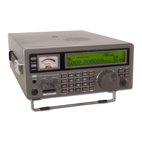
- Page 1 ® AR6000 Super Wide-band Multi-mode Receiver Operating manual AOR, LTD.
- Page 2 2-4 KEYPAD ............................ 15 2-4-1 FRONT PANEL KEYS ....................15 GETTING STARTED ........................21 3-1 MAKING THE AR6000 READY FOR OPERATION ..............21 3-1-1 CONNECT THE ANTENNA ....................21 3-1-2 CONNECT POWER .......................21 3-2 SWITCHING ON FOR THE FIRST TIME ................... 21 3-3 VOLUME CONTROL .........................
- Page 3 5-1-3 MOVING THE SPECTRUM ....................32 5-1-4 CHANGING THE MARKER FREQUENCY ..............33 5-1-5 DEACTIVATING THE SPECTRUM DISPLAY ..............33 5-2 MULTI CHANNEL RECEIVE ...................... 33 5-2-1 DUAL CHANNEL RECEIVE IN OFFSET MODE .............33 5-2-2 DUAL BAND RECEIVE ....................34 5-2-3 TRIPLE CHANNEL RECEIVE ..................35 5-3 MANAGING AN SD CARD ......................
- Page 4 8 SEARCH MODE ..........................51 8-1 SEARCH TYPE ......................... 52 8-1-1 VFO SEARCH ........................52 8-1-2 PROGRAM SEARCH .....................53 8-1-3 CYBER SEARCH ......................57 8-2 SEARCH GROUP ........................58 8-2-1 BANK LINK SETTING ....................58 8-2-2 SEARCH PAUSE ......................58 8-2-3 SEARCH DELAY ......................59 8-2-4 VOICE SEARCH ......................59 8-2-5 AUTO STORE ........................60 9 CONFIGURATION MENU ........................
- Page 5 10-12 PRESEL (PRE-SELECTION FILTER) ..................76 10-13 VIDEO OUT (VIDEO OUTPUT) ..................... 76 10-14 VIDEO IMG (VIDEO MODULATION POLARITY) ..............77 11 MISCELLANEOUS FUNCTIONS ....................77 11-1 STEP ADJUST ......................... 77 11-2 SUB DIAL SETTING ........................ 78 11-3 VFO SETTING ......................... 79 11-3-1 TRANSFER FREQUENCY TO VFO ................79 11-3-2 VFO SEARCH DELAY ....................80 11-3-3 VFO VOICE SQUELCH....................80...
-
Page 6: Introduction
Thank you for purchasing the AR6000 Super Wide-band Multi-mode Receiver. AR6000 is designed using the latest technology to ensure the highest level of performance and reliability. If you are familiar with the AR5001D operations and functions, you will find it easy to use the new AR6000 receiver. -
Page 7: Main Features
Main features: Wide frequency coverage: 9 kHz to 6 GHz, with no interruptions (Cellular blocked for the US consumer version) 45.05 MHz IF DSP (Digital Signal Processing) HF direct sampling No AGC in the analog processing circuit Computer simulated high grade RF frontend PC controllable DDS (Direct Digital Synthesizer) local oscillator Accurate reference frequency (0.01 ppm with an optional GPS unit) -
Page 8: Take Care Of Your Receiver
The AR6000 has no user adjustable internal parts. If using the AR6000 as a base station, the best short wave reception is usually achieved by grounding your shortwave antenna with a separate external earth (or ground) rod. However, consider the implications carefully if your AC building supply uses a Protective Multiple Earth (PME) system. -
Page 9: Included In This Package
Operating anomalies Should the AR6000 appear to behave strangely, normal operations may be easily achieved by performing the following steps: 1. Symptom: No control of the receiver. Action: Turn off the power switch on the front panel. Leave it off for approximately 10 seconds. - Page 10 High frequency (45.05 MHz) IF output The AR6000 has a 45.05 MHz analog IF output with 15 MHz bandwidth. The input signal to the 45.05 MHz IF stage is directly sent to the A/D converter for digital processing. This IF output signal may be suitable as an RF front end for radio signal analysis applications.
- Page 11 USB 2.0 standard interface. By using the I/Q digital output, the streamed data can be stored on a PC hard disk for future signal analysis. The I/Q digital output of the AR6000 has a wide dynamic range (without AGC processing) floating point data format.
- Page 12 P25 (APCO25) decoding (with optional APCO25 board) (conventional non-encrypted mode only) Built-in AFC (Automatic Frequency Control) AM (Amplitude Modulation) Envelope Detection (Normal AM decoder) Synchronous Detection 1. DSB (Double Side Band) synchronous 2. SSB (Single Side Band) USB/LSB (Upper Side Band/Lower Side Band) selectable synchronous AGC (Automatic Gain Control) mode/Manual RF gain mode SSB (Single Side Band)
-
Page 13: Controls And Functions
2 CONTROLS AND FUNCTIONS 2-1 FRONT PANEL 1. Power On/Off switch 2. Function switch 3. Analog S meter 4. LCD (Liquid Crystal Display) 5. Stereo headphone jack (3.5 mm stereo type) 6. ACC1 (Accessory connector) Pin #1 12 VDC output (30 mA max.) Pin #2 Detector output Pin #3... -
Page 14: Rear Panel
2-2 REAR PANEL 1. Antenna connector 1 (N type) ANT 1 25MHz-6GHz 100kHz-6GHz 100kHz-6GHz 2. Antenna connector 2 (N type) ANT 2 9kHz-3.15GHz 25MHz-3.15GHz 25MHz-3.15GHz 3. ACC2 (Accessory 2) connector Pin # Description Pin # Description 12V DC output Antenna switch A (50mA max.) No Connection Antenna switch B... -
Page 15: Lcd Display
2-3 LCD DISPLAY Frequency display mode Band scope mode Icon Function Function switch Dual channel receive (offset mode) Dual band receive (HF and V/U) GPS status (optional) Lit: Frequency reference 0.01 ppm Blink: Frequency reference 0.1 ppm Not lit: No GPS installed Key lock/Remote control mode ALARM Alarm function activated... -
Page 16: Keypad
2-4-1 FRONT PANEL KEYS POWER This key is located on the upper left corner of the front panel. Press this key to power on the AR6000. To power off the AR6000, press and hold this key for two seconds. FUNC The function key is used to select secondary functions on the keypad. - Page 17 VFO – V. MODE / 2F. BAND Press this key to select VFO mode. The AR6000 has 5 VFOs (VFO-A through VFO-E) and the selected VFO is identified by “VA”, “VB”, “VC”, “VD”, and “VE” icons on the right bottom of the LCD.
- Page 18 3 – IF BW Figure THREE for the numeric input of frequencies, bank, channel numbers, etc. Press the [FUNC] key, and press the [3] key to activate the IF bandwidth menu. In normal operation, “AUTO” will be displayed on the LCD and the IF bandwidth will be automatically selected according to the band plan.
- Page 19 8 - ALARM Figure EIGHT for the numeric input of frequencies, bank, channel numbers, etc. Press the [FUNC] key, and press the [8] key to activate the alarm function which automatically turns on the receiver at the preprogrammed time or sound a beep. 9 - SLEEP Figure NINE for the numeric input of frequencies, bank, channel numbers, etc.
- Page 20 Press this key to select the receive mode. Rotate the sub dial to select the desired received mode, and press the [MHz] key to confirm the selection. To select AUTOMODE, press and hold the [MODE] key for two seconds. The AR6000 will automatically select the receive mode, IF bandwidth, and frequency step from the pre-programmed band plan. When in auto mode, “AUTO”...
- Page 21 ENT – This key is used to confirm entry in most menus. If this key is held for two seconds in VFO mode, the AR6000 goes in to memory write mode. Use the main dial knob to select the desired memory channel number, sub dial for memory bank to store into memory.
-
Page 22: Getting Started
Do not connect to a 24V system. 3-2 SWITCHING ON FOR THE FIRST TIME Turn on the power switch on the rear panel of the AR6000. This is the main power switch. The clock will be displayed on the LCD. - Page 23 After the opening screen appears on the LCD, the main screen will then be displayed. Main screen (sample) To power off the AR6000, press and hold the power switch on the front panel for two seconds. After “AR6000 SHUT DOWN” message is displayed, the receiver will automatically power off.
-
Page 24: Volume Control
While squelch opens, “B” (busy) will appear in reverse contrast on the top left of the LCD. 3-5 VFO SELECTION The AR6000 has five (5) VFOs identified as “VA” through “VE” on the right bottom of the LCD. The term VFO historically means ‘Variable Frequency Oscillator’ and today refers to a tunable data storage which contains frequency, step, step-adjust, attenuator etc. -
Page 25: Tuning Frequency
VFO-D --- Used to transfer frequency from the search channel VFO-E --- Used to receive frequency below 25 MHz while in dual frequency receive mode The AR6000 has an auto mode setting, therefore, in most cases a proper receive mode and frequency steps are automatically selected. -
Page 26: Receive Mode
For this reason, it is necessary to change receive mode in order to monitor various transmissions. For your convenience, receive mode and tuning step size have been pre-programmed into the AR6000 auto mode band plan data at the factory to simplify the operations of the receiver, especially while you familiarize yourself with the functions. -
Page 27: Auto Mode Selection
New digital communication format for SW (Shortwave) broadcast. Proper software and external hardware are required to decode DRM (not included). 3-6-1 AUTO MODE SELECTION When in auto mode, the receive mode and tuning step size are automatically selected for you by the AR6000 microprocessor. -
Page 28: Receive Mode Selection
For above reasons, it is necessary to change the frequency step size according to the local band plan. The AR6000 has been pre-programmed at the factory with all the band plan data (specific to each market area) so that the AR6000 will automatically select the appropriate step size and mode for the frequency chosen. -
Page 29: If Bandwidth
The pre-programming of step size may be manually overridden so you may choose alternative settings at will or when band plans are updated. If you wish to change the default tuning frequency step, press the [STEP] key. The LCD will display the current frequency step and the blinking “STEP”... -
Page 30: Manually Selecting If Bandwidth
Typical examples of receive mode and IF bandwidth are: 200 kHz – VHF FM broadcast 30 kHz, 100 kHz – Wireless microphone, etc. (30 kHz for satellite FAX, too) 15 kHz – PMR, amateur band, etc. FM 6 kHz may also be used 6 kHz –... -
Page 31: Additional Settings
The AR6000 has 5 settings for the attenuator, 0 dB (AMP), 0 dB, -10 dB, -20 dB, and AUTO. To change the parameter setting, press the [ATT] key. -
Page 32: Antenna Input
Note: The manual RF gain control is not available while the receiver selects AGC mode. 4-4 ANTENNA INPUT The AR6000 has two antenna input ports. However, a total of four antennas can be used with the optional antenna relay switch. -
Page 33: Keylock
However, the volume and squelch controls remain operative. 5 ADVANCED FUNCTIONS 5-1 SPECTRUM DISPLAY The AR6000 has a spectrum display function. The frequency span can be selected between 0.4 MHz ~ 10 MHz. 5-1-1 ACTIVATING THE SPECTRUM DISPLAY In VFO mode, press and hold the [FUNC] key for two seconds, then the spectrum display screen appears on the LCD. -
Page 34: Changing The Marker Frequency
To exit from the spectrum display, press and hold the [FUNC] key for two seconds. 5-2 MULTI CHANNEL RECEIVE The AR6000 is capable of monitoring of up to three channels simultaneously. 5-2-1 DUAL CHANNEL RECEIVE IN OFFSET MODE In VFO mode, any two frequencies above 25 MHz, which are within +/- 5 MHz can be received simultaneously in offset mode with the following conditions. -
Page 35: Dual Band Receive
5-2-1-2 CHANGING THE OFFSET FREQUENCY To change the offset frequency, rotate the sub dial. The frequency will change according to the step frequency of the sub dial. 5-2-1-3 CHANGING THE AUDIO BALANCE Press the [FUNC] key, and then rotate the AF GAIN (Volume). The balance adjustment screen appears. -
Page 36: Triple Channel Receive
5-2-2-2 SETTING THE FREQUENCIES To set the main frequency, press the [UP] key and enter the frequency using the numeric keypad. To set the sub frequency, press the [DOWN] key and enter the frequency using the numeric keypad. Note: The main frequency must be above 25 MHz, and the sub frequency must be below 25 MHz. However, separate modes can be selected for both frequencies. -
Page 37: Managing An Sd Card
2. Press the [FUNC] key, and then press and hold the [VFO] key for 2 sec. to exit dual band mode. 5-3 MANAGING AN SD CARD The AR6000 has a built-in SD memory card interface used for voice recording and/or memory management. Once formatted, all data on the card will be deleted and lost. -
Page 38: Read Data From Sd Card
5-3-3 READ DATA FROM SD CARD To read memory contents of the AR6000 on the SD memory card, perform the following steps: 1. Insert a SD memory card with a printed label upward facing the slot on the front panel until you can hear a click. -
Page 39: Write Data To Sd Card
8. After reading from the file, the LCD will display the original screen. 5-3-4 WRITE DATA TO SD CARD To write memory channel or search bank contents of the AR6000 to the SD memory card, perform the following steps: 1. Insert a SD memory card with a printed label upward facing the slot on the front panel until you can hear a click. -
Page 40: Recording Audio
Key Characters SPACE (Example) To select “B”, press the [3] key, then rotate the sub dial clockwise. To move the cursor, press the [DOWN] key to the left, [UP] key to the right. 7. To confirm entry, press the [MHz] key. 8. -
Page 41: Playback Audio
Key Characters SPACE (Example) To select “B”, press the [3] key, then rotate the sub dial clockwise. To move the cursor, press the [DOWN] key to the left, [UP] key to the right. 7. To confirm entry, press the [CLR] key. 5-3-6 PLAYBACK AUDIO To playback a recorded audio, perform the following steps: 1. -
Page 42: Memory Channels And Banks
(memory channel) and each page may be overwritten with new data, so they can be used over and over again. The AR6000 has 2,000 memory channels and one priority channel. Each memory channel may hold:... -
Page 43: Storing Vfo Frequencies And Data Into Memory
The process to save a displayed VFO frequency to memory is as follows: 1. In VFO mode, select the required frequency, mode, attenuator etc. 2. Press and hold the [MHz] key for two seconds. The AR6000 will automatically find the next available vacant memory channel. - Page 44 to store the frequency into the location. (memory bank 03, channel number 25.) When the [----.-----] is displayed on the right bottom of the LCD, the selected channel is vacant. (To change the memory bank, rotate the sub dial. To change the memory channel, rotate the main dial.) 4.
-
Page 45: Memory Read
4. The memory frequency of 123.500 MHz will be displayed on the LCD. 5. If you already know the memory bank and memory channel, simply press the [0],[3],[2],[5] key. 6. The AR6000 will monitor whatever memory channel you enter into memory read. 7. To return to VFO mode, press the [VFO] key. -
Page 46: Scan – Scanning Memory Channels
7 SCAN – SCANNING MEMORY CHANNELS The AR6000 has a scan mode whereby the contents stored in the memory channels are automatically recalled and monitored very quickly for activity – scanned. Note: It is important that you do not confuse SCAN and SEARCH modes. -
Page 47: Displaying A Memory Channel Text
7-4 DISPLAYING A MEMORY CHANNEL TEXT To display a memory channel text, press the [FUNC] key and then press the [MHz] key. Each time the above step is performed, the display contents change as follows: 1. Text only 2. Text and frequency 3. -
Page 48: Starting / Stopping Select Scan
5. To delete all selected scan channels, press the [PASS] key. To cancel, press the [CLR] key. 6. Press the [MHz] key to exit from this menu. 7-5-3 STARTING / STOPPING SELECT SCAN To start select scan, you must first have at least two memory channels tagged for select scan. Press the [FUNC] key, and then press the [4] key to start select scan. -
Page 49: Delete All Pass Channels
6. Press the [MHz] to exit from this menu. 7-7 SCAN GROUP The AR6000 has 20 scan groups to be used with the bank link function and other functions. The following parameters can be registered for each of the scan groups. -
Page 50: Scan Pause
4. To confirm entry, press the [MHz] key. To set other parameters, press the [DOWN] key. 7-7-3 SCAN DELAY The scan delay parameter affects the time the AR6000 will remain on an active channel in the scan mode once the received signal has disappeared and the squelch is closed. This is particularly useful for customizing how long the receiver will wait for a reply before continuing to scan. -
Page 51: Voice Scan
When the voice scan function is activated, the scan process will stop only on active channels which have modulation (such as voice) present. The AR6000 will not remain on unmodulated channels (such as blank carriers). The parameter ranges are off, and 1 ~ 7. -
Page 52: Mode Scan
5. To confirm entry, press the [MHz] key. To set other parameters, press the [DOWN] key. 8 SEARCH MODE In search mode, the AR6000 is programmed to automatically tune between two specified frequency limits looking for activity. Before activating search mode, the squelch must be set to threshold where the background noise... -
Page 53: Search Type
The VFO search is the easiest way of searching without programming. When the VFO-A is selected as a primary VFO, the AR6000 will search between two frequencies on VFO-A and VFO-B with receive mode, frequency step set in the VFO-A. -
Page 54: Program Search
8-1-2-3 FORCING THE SEARCH TO RESUME If the AR6000 stops on an unwanted busy frequency, rotate the main tuning dial knob or press the [UP] key or [DOWN] key to force the search process to resume from the current frequency displayed. - Page 55 8-1-2-6 PROGRAMMING A SEARCH BANK Each of the 20 search banks may be programmed with different frequency limits, receive modes, etc. To program a search bank, perform the following steps: 1. Press the [FUNC] key, and then press the [1] key to access the search program menu. 2.
- Page 56 To enter “N”, press the [4] key and rotate the sub dial clockwise for 1 click. Then press the [UP] key. To enter “D”, press the [3] key and rotate the sub dial clockwise for 3 clicks. To accept data entry, press the [MHz] key. [Key assignment for text input] [1]: “...
- Page 57 Up to 30 pass frequencies can be registered for each search bank. A total of 1200 pass frequencies can be registered in the AR6000. It is important to understand the pass function before taking action or transmissions may be missed.
-
Page 58: Cyber Search
1. Press the [FUNC] key, and then press and hold the [.] key for two seconds. The following delete menu will appear with “DEL MEM-CH” in reverse contrast. 2. Press the [DOWN] key to move the cursor downward. Select “DEL F-PASS” in reverse contrast. 3. -
Page 59: Search Group
8-2 SEARCH GROUP The AR6000 has 20 search groups to be used with the bank link function and other functions. The following parameters can be registered for each of the search groups. Bank link setting • Search pause • Search delay •... -
Page 60: Search Delay
4. To confirm entry, press the [MHz] key. To set other parameters, press the [DOWN] key. 8-2-3 SEARCH DELAY The search delay parameter affects the time the AR6000 will remain on an active frequency in search mode once the received signal has disappeared and the squelch is closed. This is particularly useful for customizing how long the receiver will wait for a reply before continuing to search. -
Page 61: Auto Store
The parameter ranges are off, and 1 ~ 7. To set the voice search parameter, perform the following steps: 1. Press the [FUNC] key, and then press the [SRCH] key. The search link screen will appear. 2. Select the bank link group number, and then press the [DOWN] key three times. The voice search screen will appear. -
Page 62: Configure Lamp
MEMORY CHANNEL ASSIGN Assign a number of memory channels 9-1 CONFIGURE LAMP The AR6000 is equipped with high intensity green LEDs to illuminate the LCD when operating in areas of low level lighting. The lamp may be configured in two ways: This is default setting. -
Page 63: Configure Beep
Or, press the [DOWN] key to move to the next item on the configuration menu. 9-2 CONFIGURE BEEP The AR6000 emits confirmation ‘beeps’ while the keypad is used. A ‘HIGH’ pitched beep indicates correct operation while a ‘LOW’ pitched beep indicates that an error or unexpected entry has taken place. The volume of the beep is independent of the main volume control and can be separately defined. -
Page 64: Configure Local (Location Setting)
Or, press the [DOWN] key to move to the next item on the configuration menu. 9-4 CONFIGURE LOCAL (LOCATION SETTING) The AR6000 is capable of selecting the user’s location settings. This function is especially useful when you travel abroad with your receiver. The AR6000 has preprogrammed data for three different locations (Europe, Japan, and U.S.A.) which contain the respective band plans and receive modes, etc. -
Page 65: Configure Ant Program
Or, press the [DOWN] key to move to the next item on the configuration menu. 9-7 CONFIGURE ANT PROGRAM The AR6000 has two antenna input ports and may be assigned according to the receive frequencies. Note: 1. When the receiving frequency is below 25 MHz, antenna 2 must be used. -
Page 66: Configure Sd Info
To continue programming, repeat above steps from step 3. 9-8 CONFIGURE SD INFO The AR6000 has a built-in SD memory card interface used for voice recording and/or memory management. To display information of the inserted SD memory card, perform the following steps: 1. -
Page 67: Configure Write To Sd
6. A sub screen will appear and display information showing total available recording time and the total size of the SD memory card. 7. Press the [MHz] key to exit from this screen. 8. Press the [CLR] key to exit the configuration menu. 9-9 CONFIGURE WRITE TO SD To write memory channel or search bank contents to the SD memory card, perform the following steps: 1. -
Page 68: Configure Read From Sd
Key Characters SPACE (Example) To select “B”, press the [3] key, then rotate the sub dial clockwise. To move the cursor, press the [DOWN] key to the left, [UP] key to the right, [PASS] key to erase the character. 7. To confirm entry, press the [MHz] key. 8. -
Page 69: Configure Sd Format
5. Press the [MHz] key. 6. A sub screen will appear with a list of memory data file displayed. 7. To change the memory page, rotate the sub dial to select. 8. Using the [UP] key or [DOWN] key, select the desired file name. 9. -
Page 70: Configure Version
4. Press any key to return to a standard display. 9-13 CONFIGURE INITIALIZE (RESET) Initializing the AR6000 will return it to the original factory default settings and all memory contents will be deleted. To initialize the AR6000, perform the following steps: 1. -
Page 71: Option Menu
To change the number of memory channels, perform the following steps: 1. Press the [FUNC] key, and then press the [kHz] key. 2. Press the [UP] key to select “MEMORY CHANNEL ASSIGN” in reverse contrast.. 3. Rotate the sub dial to select the desired memory bank. 4. -
Page 72: Notch (Auto Notch)
To activate the function, perform the following steps: 1. Press the [FUNC] key, and then press the [0] key. 2. Press the [DOWN] key to select “LSQL HYS” in reverse contrast. 3. Rotate the sub dial to select the hysteresis level from the range of 0 ~ 9 dB. 4. -
Page 73: Nb (Noise Blanker)
10-5 NB (NOISE BLANKER) Noise blanker function is effective for pulse noise on the receive signal. To activate the function, perform the following steps: 1. Press the [FUNC] key, and then press the [0] key. 2. Press the [DOWN] key four times to select “NB” in reverse contrast. 3. -
Page 74: Afc (Automatic Frequency Control)
10-9 CTCSS (CONTINUOUS TONE CONTROLLED SQUELCH SYSTEM) CTCSS function will enable the AR6000 to selectively receive only specifically modulated sub-audible tones or to verify the CTCSS frequency used. Note: This function operates only in the NFM mode with a frequency of 25 MHz or higher. -
Page 75: Dcs (Digital Coded Squelch)
3. Rotate the sub dial to toggle between OFF, ALL, or to select the inversion frequency from the range of 60 Hz ~ 254.1 Hz as from the list below. To set CTCSS to ALL, you can also press the [PASS] key. 60.0 67.0 69.3... -
Page 76: Dtmf (Dual Tone Multi Frequency)
10-11 DTMF (DUAL TONE MULTI FREQUENCY) DTMF tones are used by many VHF/UHF communications services and amateur radio operators to control switching devices and to enable selective calling. The AR6000 has the capability to decode all 16 DTMF tones. The decoded DTMF characters will automatically be displayed on the LCD when the function has been activated. -
Page 77: Presel (Pre-Selection Filter)
10-13 VIDEO OUT (VIDEO OUTPUT) Note: This function operates with a frequency of 25 MHz or higher. The AR6000 has a built-in (analog) video decoder and composite video signal output is available from the video output connector on the rear panel. -
Page 78: Video Img (Video Modulation Polarity)
In some cases, certain FM video signals may be transmitted with an IF frequency reversed, and consequently, the received video signal cannot be properly decoded. The AR6000 has a shift direction reverse function to correct the problem. To activate the video modulation polarity function, perform the following steps: 1. -
Page 79: Sub Dial Setting
To activate the step adjust function, perform the following steps: 1. Press the [STEP] key. 2. Press the [PASS] key. “*” (asterisk) appears right next to “STEP”. 3. Enter the new step frequency using a numeric keypad or rotating the sub dial. 4. -
Page 80: Vfo Setting
AR6000 will switch to VFO-D automatically. While searching • Press the [SRCH] key. The active frequency will be transferred to VFO-D, and the AR6000 will switch to VFO-D automatically. 11-3-1-2 WHILE IN SCAN MODE While stopping on the busy channel or in memory read mode •... -
Page 81: Vfo Search Delay
11-3-2 VFO SEARCH DELAY The VFO search delay parameter affects the time the AR6000 will remain on an active frequency in VFO search mode once the received signal has disappeared and the squelch closed. This is particularly useful for customizing how long the receiver will wait for a reply before continuing to search. -
Page 82: Hf (High Pass Filter)
There are three available selections for cut off frequencies: 3 kHz, 6 kHz, and THROUGH. The low pass filter is automatically selected according to the IF bandwidth. Conditions Cut off frequency IF bandwidth: Less than 6 kHz 3 kHz IF bandwidth: 15 kHz 6 kHz IF bandwidth: More than 30 kHz THRU... -
Page 83: De-Emphasis
11-4-3 DE-EMPHASIS The audio de-emphasis is only applicable to WFM mode and affects the sharpness of recovered audio. The value of de-emphasis varies from country to country. There are two available selections for audio de-emphasis of value: 50 μS, and 75 μS. To select audio de-emphasis value, perform the following steps: 1. -
Page 84: Clock
Each clock can also display a three character text comment for identification. When the AR6000 is switched off, but power is still connected, the clock is displayed on the LCD without back illumination. 11-5-1 INITIAL SET... - Page 85 e) Press the [4] key. Rotate the sub dial to select “T”. If needed, the [.] key adds as blank space and the [PASS] key erases the selected character. 8. Press the [MHz] key to adjust clock 2. 11-5-1-2 CLOCK 2 1.
-
Page 86: Displaying The Clock
5. Rotate the sub dial to adjust day. 6. Press the [MHz] key to confirm entry. 11-5-2 DISPLAYING THE CLOCK Press the [FUNC] key, and then press the [7] key. Rotate the sub dial to toggle between clock 1 and clock 2. To return to a standard display, press the [FUNC] key, and then press the [7] key. -
Page 87: Alarm Activation
Once the alarm has been activated, “ALARM” will be displayed on the top middle of the LCD. The AR6000 will switch on automatically once per day (presuming the receiver had been switched off) on a daily basis at the defined volume level and for the programmed length time before automatically switching off again until the same time on the following day. -
Page 88: Priority Function
The priority checking is accomplished by momentarily tuning the receive circuit to the priority frequency to see if it is active. If the activity is found, the AR6000 will remain on the active frequency until the signal disappears. If no activity is detected, the receiver returns to the VFO frequency, scan channel or search bank from where it originated. -
Page 89: Activating Priority Function
The normal position for the AR6000 RF gain control is fully counterclockwise when set at its most sensitive. As the control is rotated clockwise, the S-meter will advance to indicate what strength signal is required to produce solid and readable results. -
Page 90: Pc Control
The USB (type B) connector is designed to connect directly to the USB port of a PC. All functions of the AR6000 can be controlled by a PC by means of the USB interface. A free control and memory management software can be downloaded at: http://www.aorja.com/support/software.html... -
Page 91: Specifications
13 SPECIFICATIONS... -
Page 92: Limited Warranty (Usa Only)
AOR USA, Inc. (AOR) warrants its receivers as described below: AOR will repair or exchange equipment as a result of defects in parts or workmanship for a period of one year from the date of original retail purchase from an authorized AOR dealer. - Page 93 If you have questions about this limited warranty, or the operation of your AOR product, contact AOR at (310) 787-8615 during normal business hours (9 am ~ 5 pm Pacific Time Zone), or write to AOR, 20655 S. Western Ave., Suite 112, Torrance, CA 90501. You may also send a fax to AOR at (310) 787-8619.
- Page 95 Manufacturer: AOR, LTD. 2-6-4, Misuji, Taito-Ku, Tokyo, 111-0055, Japan URL: www.aorja.com US distributor: AOR USA, INC. 20655 S. Western Ave. Suite 112 Torrance, CA 90501 Phone: 310-787-8615 Fax: 310-787-8619 URL: www.aorusa.com e-mail: info@aorusa.com Dec.15, 2017 Printed in Japan...
Need help?
Do you have a question about the AR6000 and is the answer not in the manual?
Questions and answers