Table of Contents
Advertisement
Quick Links
WARNING - Reliance on this Manual Could Result in Severe Bodily Injury or Death!
This manual is out-of-date and is provided only for its technical information, data and capacities. Portions of this manual
detailing procedures or precautions in the operation, inspection, maintenance and repair of the product forming the subject
matter of this manual may be inadequate, inaccurate, and/or incomplete and cannot be used, followed, or relied upon.
Contact Conair at info@conairgroup.com or 1-800-654-6661 for more current information, warnings, and materials about
more recent product manuals containing warnings, information, precautions, and procedures that may be more adequate
than those contained in this out-of-date manual.
U S E R G U I D E
UGB011-0207
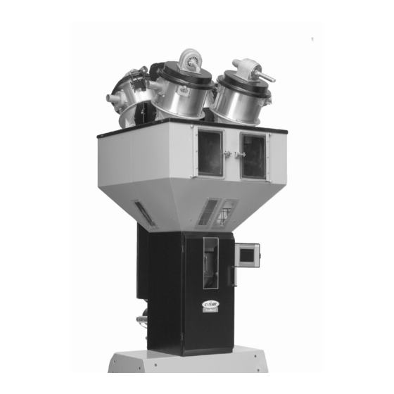
TrueBlend
Gravimetric Blender
Software Version V2.7
USER INSTRUCTIONS • About this operating manual • Warranty and liability • Layout of the manual • Meaning of safety
information Display conventions • Pictograms for safety and information Abbreviations • SAFETY • General • Designated
use • Sources of danger • Safety devices • Warning symbols on the unit • Information for the operator • Information for
operating and maintenance personnel • TECHNICAL SPECIFICATIONS • Manufacturer • Specifications • TRANSPORT AND
SETUP • Unpacking • Lifting • Setup • Positioning controller • Making connections • Stowing discharge chute
STRUCTURE AND FUNCTION • Structure of the unit • Brief description of the functional units • Layout of the material
hoppers • Operating modes • Gravimetric mode • Volumetric mode • Combined mode • COMMISSIONING • OPERATION
Switching on • Menu structure • Navigation • Starting and stopping the metering and mixing process • Switching off
Logging in/logging out • Commissioning • Mixing process • Component setup • GRAVICOLOR Setup • Working with recipes
Changing material for a component (also valid for all other components) • Checking total throughout • Creating reports
Co rpo r a te O f fic e : 41 2.3 12. 600 0 | I n s t ant Acc es s 2 4/7 ( Pa r ts an d Se rv ice ): 800 . 458. 196 0 | P a rts and Se rvic es : 814 .43 7.6 861
™
www.conairnet.com
Advertisement
Table of Contents
Troubleshooting

Related Manuals for Conair TrueBlend TB45-4


Summary of Contents for Conair TrueBlend TB45-4
- Page 1 Contact Conair at info@conairgroup.com or 1-800-654-6661 for more current information, warnings, and materials about more recent product manuals containing warnings, information, precautions, and procedures that may be more adequate than those contained in this out-of-date manual.
- Page 3 © 2007 Conair The information contained in these operating instructions, including any transla- tion thereof, is the property of Conair and may not be reproduced or transmitted in any form or by any means (electronic, mechanical, photocopying, recording or otherwise, nor stored in any retrieval system of any nature for any purpose) with- out the express written authority of Conair •...
-
Page 4: Table Of Contents
Contents TrueBlend™ Contents 1.0 User instructions....................7 About this operating manual..................7 Layout of the manual....................8 Meaning of safety information ................. 9 Pictograms for safety and information..............10 Abbreviations......................10 2.0 Safety ........................ 11 General........................11 Safety Hazards...................... 11 Safety Features ..................... - Page 5 TrueBlend™ Contents 4.5.2 Electrical connection .................. 33 4.5.3 Hopper loader connection (option)............. 34 5.0 Structure and function ..................35 Structure of the unit....................35 Brief description of the functional units (Item numbers refer to diagram on previous page)........................ 36 Layout of the material hoppers ................36 5.3.1 For four component blenders..............
- Page 6 Contents TrueBlend™ Start-up........................52 7.7.1 Checking functions in manual mode ............52 7.7.2 Calibrating ....................56 7.7.3 Input TrueBlend Model/Name (for service users only!) (Level 3) ... 61 7.7.4 Input TrueBlend name................62 7.7.5 Activating Batch Setting ................62 Blending process....................65 7.8.1 Assigning components –...
- Page 7 TrueBlend™ Contents 7.18 Maintenance ......................98 7.19 Hopper loaders (Optional)................... 100 7.19.1 Go to Material loading (conveying) overview screen ....... 100 7.19.2 Switching on hopper loaders..............100 7.19.3 Changes to Loader Screen ..............102 7.19.4 Loader Alarm Settings ................102 7.19.5 Settings ....................
- Page 8 Contents TrueBlend™ Cleaning ......................133 9.7.1 Cleaning material hopper and mixing chamber........133 10.0 Decommissioning and disposal ............134 10.1 Decommissioning the unit ................... 134 10.2 Disposing of unit parts..................134 11.0 Appendix ....................135 11.1 Menu structure ....................135 11.1.1 Operating levels/password level ..............
-
Page 9: User Instructions
TrueBlend™ User Instructions 1.0 User instructions 1.1 About this operating manual This operating manual is a component of the TrueBlend Gravimetric blender. It contains important instructions on the correct operative and maintenance of the unit. Follow these instructions to avoid dangers, to prevent repair expenses and downtime and to increase the service life of the unit. -
Page 10: Layout Of The Manual
User Instructions TrueBlend™ 1.2 Layout of the manual This manual is classified into several main parts: • User information, • Safety, • Technical specifications, • Transport and setup, • Structure and function, • Operation, • Maintenance and repair, • Decommissioning and disposal, •... -
Page 11: Meaning Of Safety Information
TrueBlend™ User Instructions 1.3 Meaning of safety information Safety instructions are placed before the work steps. Read the safety instructions carefully before carrying out the subsequent operation. If safety instructions are not followed, serious personal injury - possibly with fatal results - and property and environmental damage may occur! The safety instruction in this operating manual are indicated with a symbol. -
Page 12: Pictograms For Safety And Information
User Instructions TrueBlend™ 1.4 Pictograms for safety and information In this operating manual you will find sections of text that a re identified by picto- grams. The meaning of the pictograms is described below. Pictogram for general identification of hazards. This pictogram occurs in con- nection with safety instructions (see 1.3 Meaning of safety information). -
Page 13: Safety
TrueBlend™ Safety 2.0 Safety 2.1 General This chapter contains basic safety instructions for working with the gravimetric batch blending unit. Observe all the instructions for the operation and maintenance of the unit in this chapter. In addition, observe the warning notices that are placed before the action direc- tions where the operating steps are described. -
Page 14: Safety Features
Safety TrueBlend™ SLIDE GATE/MIX CHAMBER NEVER use your fingers to move a sticking slide gate under the mix cham- ber. 2.3 Safety Features SAFETY INTERLOCK SWITCH The ACCESS DOOR is equipped with a safety interlock switch that prevents the mix motor from running and the slide valves from operating. DO NOT defeat this safety switch HOPPER FINGER GUARDS Finger guards are fitted into each hopper compartment. - Page 15 Do not make any changes to the unit. Any changes may adversely affect the safety of the unit. Designated use includes following this operating manual and following the speci- fied maintenance intervals and conditions. Please contact Conair if you have any questions about the designated use of the unit. NOTE Edition: February 2007...
-
Page 16: Sources Of Danger
Safety TrueBlend™ 2.5 Sources of danger The unit is manufactured to comply with the state of the art in technology and the generally accepted rules of safety engineering. However, operation of the unit may give rise to dangers for life and limb of the operator or third parties or dam- age to the unit or other property. - Page 17 TrueBlend™ Safety The sources of danger and the consequences are shown in more detail below: Danger source Consequences Electrical system Fatal injury by electric shock! High voltages can cause life-threatening currents in the body and electric shock. Allow only trained and qualified electrical tech- nicians to work on the electrical system.
- Page 18 Safety TrueBlend™ Danger source Consequences Pneumatic seal on the Danger of injury by moving parts! discharge slide gate Horizontally moving pneumatic cylinders can bottom of mix chamber cause crushing, impact and shearing injuries and bone fractures. Do not reach into the pneumatic discharge slide gate during normal operation and during manual operation.
-
Page 19: Safety Devices
TrueBlend™ Safety 2.6 Safety devices Safety devices protect your health and your life. Do not operate the unit without effective safety devices. DANGER OF INJURY! The operator runs the risk of injury if the safety devices are not operating cor- WARNING! rectly. -
Page 20: Detachable Material Hopper Procedure
Safety TrueBlend™ Safety device Safety function Safety guard Prevents injury by crushing and impact at the pneu- matic cylinder of the supply hopper. Safety interlock Stops the mixer motor when the main door is opened. switch EMERGENCY STOP Stops all movement of the machine. switch Padlock Locks the switch to prevent unauthorized persons... -
Page 21: Warning Symbols On The Unit
TrueBlend™ Safety 2.7 Warning symbols on the unit The instructional, warning and prohibition signs on the unit are a component of the operating manual. Observe and follow these signs in the same way as with the manual. Keep the signs clean and legible and never remove them, paint over them or stick other signs over them. -
Page 22: Meaning Of Warning Symbols On The Unit
Safety TrueBlend™ 2.7.2 Meaning of warning symbols on the unit Symbol Meaning Explanation Warning of hazardous elec- Only electrical technicians may trical voltage work on the electrical system. Warning of injury to hands Do not reach into the pneumatic seal on the supply hoppers and the discharge slide gate during operation. -
Page 23: Information For Operating And Maintenance Personnel
TrueBlend™ Safety 2.9 Information for operating and maintenance personnel Persons who are required to operate and maintain the unit must read and under- stand the operating manual, particularly the section on safety, before starting work. The following safety instructions are particularly important for avoiding personal injury and property damage: •... -
Page 24: Technical Specifications
† The optional flow control valve will mount inside the 115V/1 phase/60 hz chassis in the space of the manual slide valve. Conair recommends using the optional flow control valve when 230V/1 phase/50 hz mounting the blender on a stand, surge bin or hopper. - Page 25 The optional flow control valve will mount inside the Shipping 270 {122} chassis in the space of the manual slide valve. Conair Voltage total amps recommends using the optional flow control valve when mounting the blender on a stand, surge bin or hopper.
- Page 26 Voltage total amps † The optional flow control valve will mount inside the 115V/1 phase/60 hz chassis in the space of the manual slide valve. Conair 230V/1 phase/50 hz recommends using the optional flow control valve when Compressed air requirements mounting the blender on a stand, surge bin or hopper.
- Page 27 † The optional flow control valve will mount inside the chassis in the 115V/1 phase/60 hz space of the manual slide valve. Conair recommends using the 230V/1 phase/50 hz optional flow control valve when mounting the blender on a stand, Compressed air requirements surge bin or hopper.
- Page 28 † The optional flow control valve will mount inside the chassis in the space Compressed air requirements of the manual slide valve. Conair recommends using the optional flow Discharge valves 90 psi @ 0.2 ft /min {6 bars @ 0.09 control valve when mounting the blender on a stand, surge bin or hopper.
- Page 29 † The optional flow control valve will mount inside the chassis in 230V/1 phase/50 hz the space of the manual slide valve. Conair recommends using Compressed air requirements the optional flow control valve when mounting the blender on a Discharge valves 90 psi @ 0.2 ft...
- Page 30 Shipping 1715 {778} 1748 {793} 1782 {808} The optional flow control valve will mount inside the chassis in the space of the manual slide valve. Conair Voltage total amps recommends using the optional flow control valve 220V/1 phase/50 hz 11.3 11.3...
- Page 31 Use of reducer inserts will lower the rate shown. 400V/3 phase/50 hz The optional flow control valve will mount inside the 480V/3 phase/60 hz chassis in the space of the manual slide valve. Conair 575V/3 phase/60 hz recommends using the optional flow control valve Compressed air requirements when mounting the blender on a stand, surge bin or hopper.
- Page 32 Use of reducer inserts will lower the rate shown. 400V/3 phase/50 hz The optional flow control valve will mount inside the 480V/3 phase/60 hz chassis in the space of the manual slide valve. Conair 575V/3 phase/60 hz recommends using the optional flow control valve Compressed air requirements when mounting the blender on a stand, surge bin or 0.3 ft...
-
Page 33: Transport And Setup
TrueBlend™ Transport and Setup 4.0 Transport and setup 4.1 Unpacking M A T E R I A L D A M A G E ! Forces that are exerted on the load cell from outside when attaching and re- CAUTION! moving the weigh bin load cell may damage the very sensitive load cell. -
Page 34: Setup
Transport and Setup TrueBlend™ 4.3 Setup The unit can be mounted on the processing machine or operated as a centralized mixing station. A frame with reservoir hopper and exhaust box is available if it is used as a centralized mixing station. The frame can be bolted to the floor. Make sure that the base is as even as possible. -
Page 35: Making Connections
TrueBlend™ Transport and Setup 4.5 Making connections 4.5.1 Compressed air connection Connect the air hose [1] to the compressed air connection of the unit [2]. The operating pressure must be at least 0.6 MPa (87.0 psi) (6 bar). Check the operating pressure with the manometer [3] and if it is different set it to 0.6 MPa. -
Page 36: Hopper Loader Connection (Option)
Transport and Setup TrueBlend™ 4.5.3 Hopper loader connection (option) 4 position Position 1 Position 2 Position 4 Position 3 6 position Position 1 Position 2 Position 3 Position 6 Position 5 Position 4 (250-900 models only) Fig. 7: Connecting hopper loaders Edition: February 2007... -
Page 37: Structure And Function
TrueBlend™ Structure and Function 5.0 Structure and function 5.1 Structure of the unit Hopper loader Supply hopper a. TB 45 (4 quick access bins) b. TB 100 (2 fixed, 2 quick access bins) Material Vertical dispense valve Weighed batch Level Sensor Manual side gate (Machine mount) Mixing agitator... -
Page 38: Brief Description Of The Functional Units (Item Numbers Refer To Diagram On Previous Page)
Structure and Function TrueBlend™ 5.2 Brief description of the functional units (Item numbers refer to diagram on previous page) The TrueBlend meters and mixes free-flowing plastic granulate (regrind and natural material) and additives. The unit mixes four to six materials, depending on model and configuration. -
Page 39: For Four Component Blenders
TrueBlend™ Structure and Function 5.3.1 For four component blenders Based on the blender size, the volume of the blender material hopper can vary. On smaller blenders, material hoppers can be removable after unlocking the retainer mechanism used for securing the hopper. This is true with all positions on the TB45 series and color/additive positions (3&4) on the TB100 series. -
Page 40: Operating Modes
Structure and Function TrueBlend™ Pos 1 & 2, Main components 6 position Pos 3 & 6, Main or additive Position 1 Position 2 components Pos 4 & 5, Additive components Position 3 Position 6 Controller location Position 5 Position 4 Front door –... -
Page 41: Gravimetric Mode
TrueBlend™ Structure and Function 5.4.1 Gravimetric mode The metering sequence is identical as outlined below with every metering cycle unless Precision Additive™ (PREC) is selected: The regrind is metered by the vertical cone valve as a percentage of the whole batch and fed into the weigh bin. The required quantity of natural material is calculated by the controller and dispensed as the next component. -
Page 42: Start-Up
Start-up TrueBlend™ 6.0 Start-up Please remove the protective film on the touchscreen control for optimum performance IMPORTANT Familiarize yourself with the basic functions of the controller before start-up (see chapter 7.7). 7.0 Operation The TrueBlend series blender is controlled at the touchscreen on the operator sta- tion controller. -
Page 43: Menu Structure
TrueBlend™ Operation The start screen appears. You are at oper- ating level "0". • Press the icon for the gravimetric batch blending unit (TrueBlend symbol) to open the "TrueBlend Status" screen. • IF your unit has the blender/loader con- trol option, •... -
Page 44: Explanation Of The Navigation Buttons
Operation TrueBlend™ 7.3.1 Explanation of the navigation buttons OVERVIEW (UNIT HOME) Press this button to open the program start screen. The button is visible but disabled on the "Overview" start screen. System settings menu SETTINGS From the overview screen, press this but- ton to open a screen that enables access to various settings. - Page 45 TrueBlend™ Operation Loader settings screen SETTINGS This screen is accessible from the “Loader Status” and all other loader screens. Alarm overview screen ALARM In the event of an alarm message press this button to gain direct access to the alarm overview. The button is visible but disabled on the "Alarm Overview"...
- Page 46 Operation TrueBlend™ Help button HELP Press this button to find help on specific functions (online help is not yet imple- mented). This is an example of a help screen. Disabled button DISABLED Navigation bar functions that are not available are disabled (grayed out). Edition: February 2007...
-
Page 47: Explanation Of Keypad Screens
TrueBlend™ Operation 7.3.2 Explanation of keypad screens Input with keypad When operating the controller you are prompted to input numbers or words. When the relevant input field is pressed a numeric or alphabetical keypad (separate capital and lower case) opens, which you can use to make your in- puts. -
Page 48: Explanation Of Additional Screen Icons
Operation TrueBlend™ Scroll Press the right/left arrows to scroll forward and back (e.g. with settings for components or recipes). 7.3.3 Explanation of additional screen icons Alarm display In the event of an alarm a warning triangle is dis- played at the top right corner. The alarm mode can be set to specify when an alarm is displayed and how the unit behaves (see 7.9.3 Input Alarm mode). -
Page 49: Starting And Stopping The Blending Process
TrueBlend™ Operation 7.4 Starting and stopping the blending process 7.4.1 Starting blender process (with set values or factory setting) Press the blender icon. The “TrueBlend Status” screen opens. Press the button to start the blending process automatically with the last set values or the factory settings. -
Page 50: Turning Off The Power
Operation TrueBlend™ 7.5 Turning off the power 7.5.1 Stopping the blender at the end of a cycle From the “Blender Status” screen. Press the button. The cycle is stopped. The button switches to (yellow bar), after the (gray bar). batch is finished to If an alarm message is received when switching off and the unit does not switch off, see chapter 8 Alarms messages and trouble-shooting. -
Page 51: Logging In/Logging Out
TrueBlend™ Operation 7.6 Logging in/logging out 7.6.1 User levels and password input (for service users only!) (Level 3) The system covers several user levels: • Level : enables access to all guest functions (no password protection) • Level : enables access to all operator functions (password: 3333) •... -
Page 52: Auto Logout (For Service Users Only!) (Level 3)
If you change a password it is important that you note your new password. If you NOTE forget your password, contact Conair Service. Press the field beside auto logout (min) and enter the number of min- utes before you will be automatically logged out. -
Page 53: Parameters/Global Reset (For Service Users Only!) (Level 3)
7.6.4 Parameters/Global Reset (for service users only!) (Level 3) The overscreen Press the button beside "Parameters". Please contact Conair service before attempting to make a change to the parameters, number or value. Currently, IMPORTANT there are no parameter functions that can be set or changed. -
Page 54: Start-Up
Operation TrueBlend™ 7.7 Start-up Please remove the protective film on the touchscreen control for optimum performance IMPORTANT 7.7.1 Checking functions in manual mode All mechanical parts can be manually actuated with the "Manual Mode" function. If a vertical valve or the mix discharge is opened in manual mode, they are closed automatically by switching the main power switch to OFF or if the power fails. - Page 55 TrueBlend™ Operation If the unit is running or is being calibrated, it is locked to prevent testing of the manual operation. NOTE Testing alarm beacon Press and hold the button to check that the alarm beacon and horn operates. These devices are located on the door of the electrical power box.
- Page 56 Operation TrueBlend™ Checking weigh bins, mixers and dis- charge slide gates Press the buttons beside the unit icon to test the function of the weigh and mix chamber components. Press the first button to open and close the weigh bin. Press the middle button to switch the mixer on and off.
- Page 57 TrueBlend™ Operation To the right of the mixer icon press the middle The mixing blades must rotate. Open the safety door. The mixing blades must stop. Close the safety door. The mixing blades should rotate again. This screen mask will only be closed when all actions have been completed.
-
Page 58: Calibrating
Operation TrueBlend™ 7.7.2 Calibrating Conair recommends performing a manual calibration at start-up or material change with a dramatic change in the bulk density of the material being blended. This allows the blender to reach its optimal working point more NOTE quickly. - Page 59 TrueBlend™ Operation Zero calibration Press "0" is displayed for "Actual Weight". Full calibration (for service users only!) (Level 3) Press to open the "Full Cali- bration" screen. Before the "Full Calibration" screen ap- pears, you will be reminded that a full cali- bration cannot be interrupted: Press "Continue"...
- Page 60 Operation TrueBlend™ Model Calibration Weight TB045 750 g TB100 1,250 g TB250 3,000 g TB500 6,000 g TB900 10,000 g TB1800 22,000 g TB2500 30,000 g TB3500 50,000 g If you wish to change the reference weight, press the number input field and enter the desired weight.
- Page 61 Finally it is switched to the preset batch weight. Conair recommends performing a manual calibration at start-up or material change with a dramatic change in the bulk density of the material being blended.
- Page 62 Operation TrueBlend™ "1" indicates the material hopper number. You can scroll forward and back with the arrows. Press for material hopper "1". Press again to empty the weigh bin. Run the process for all components that require calibration. The screen cannot be closed until the pro- Important: cedure is completed.
-
Page 63: Input Trueblend Model/Name (For Service Users Only!) (Level 3)
TrueBlend™ Operation 7.7.3 Input TrueBlend Model/Name (for service users only!) (Level 3) In the "Overview" screen press the TrueBlend icon. The "TrueBlend Status" screen opens. Press The "Settings" screen appears. Press to open the "TrueBlend Model/Name" screen. The "TrueBlend Model/Name" screen appears. -
Page 64: Input Trueblend Name
Operation TrueBlend™ 7.7.4 Input TrueBlend name In the "Overview" screen press the TrueBlend icon. The "TrueBlend Status" screen opens. Press The "Settings" screen appears. Press to open the "TrueBlend Model/Name" screen. The "TrueBlend Model/Name" screen ap- pears. Assign a name to the unit with alpha- numeric keypad to give it a unique identification. - Page 65 TrueBlend™ Operation To activate the Batch Mode, press the off button in the top panel position. The “gray” button will change to “green” indicating this mode is now activated. Next enter the target weight in the next panel position. The units will be either “lbs” or “kg”. If you need to change from one to the other, please refer to section 7.15 System Setup.
- Page 66 Operation TrueBlend™ When the target value has been reached, a screen mask will appear indicating “Target weight of the dispense has been reached”. There is an acknowledge button “OK” to remove the message. NOTE Reaching the preset target weight will also stop the blender operation. To begin another Batch after resetting, return to the Blender Status screen and press the On/Off button.
-
Page 67: Blending Process
TrueBlend™ Operation 7.8 Blending process 7.8.1 Assigning components – factory default setting The components are assigned at the factory as follows: Component 1: regrind Component 2: natural material Component 3: additive/natural (color) Component 4: additive/natural (color) Component 5: additive/natural (color) Component 6: additive/natural (color) The assignment of the components can also be changed (see 7.9 Component setup). - Page 68 Operation TrueBlend™ 6 position Position 1 Position 2 Position 3 Position 6 Controller location Position 5 Position 4 Front door – mix chamber Fig.12: Layout of the material hoppers – six position models (only available on TB250, TB500, TB900, TB1800, TB2500, and TB3500) Position 1 Position 2 Position 1...
-
Page 69: Example Of A Mixing Process
TrueBlend™ Operation 7.8.2 Example of a mixing process Initial values: Total batch weight: 1000 g (TB Model TB100) Number of materials: 4 Settings: Regrind: 20% Natural material: AUTO (100% of balance batch after R, AB and AN taken out Additive batch: 10% Additive natural (Color): 2% ×... -
Page 70: Typical Dispense Cycle Based (7.8.2) Settings
Operation TrueBlend™ 7.8.3 Typical dispense cycle based (7.8.2) settings 1st Step: regrind is metered 2nd Step: Natural material is calculated regrind 20% of total weight = 200 g as 100% of the balance of batch = 686 g (automatically calculated/metered) 3rd Step: additive natural is metered 4th Step: additive batch is metered (Color) 2% of N = 13.7 g... -
Page 71: Component Setup
TrueBlend™ Operation If too much or too little was metered in a batch, this is compensated accordingly The metering process is self-optimizing on the next batch. The regrind is metered first and deducted from the total batch weight. If there is more than one virgin material, the percentages are interpreted as ratios of the vir- gin materials and dispensed next. -
Page 72: Input Of Material Percentages
Operation TrueBlend™ 7.9.1 Input of material percentages Input the percentage for the material component by pressing the input field beside "Percent %". Input the value with the numeric key- pad. Note: If using multiple naturals, they must equal 100%. Confirm the value with The metering rate in g/s is automatically learned by the system, but by completing a manual calibration the blender hones in on... -
Page 73: Input Alarm Mode
TrueBlend™ Operation 7.9.3 Input Alarm mode Every material component can be assigned a specific alarm mode. The alarm mode shows the alarm response to overmetering or undermetering. The "Warn" mode is set for regrind and “stop” for natural and addi- tives at the factory: Press the down arrow for the selection box and select the desired alarm mode. -
Page 74: Trueblend Setup
Operation TrueBlend™ 7.10 TrueBlend Setup Operating mode, batch weight, mixing time and interval time can be set in True- Blend Setup. Press the TrueBlend body icon (green column) in the center of the "TrueBlend Status" screen. The TrueBlend setup will come up. 7.10.1 Setting Operating mode The operating mode specifies whether the unit will operate gravimetrically, volu- metrically or in mixed operating mode (see 5.3.1 Operating modes). -
Page 75: Setting Weigh Bin Batch Weight
TrueBlend™ Operation 7.10.2 Setting Weigh Bin Batch weight Materials with a lower bulk densities (ca. <35 lb/cu ft) may not fit in the weigh bin and granulate may overflow. The batch weight must be reduced in this case. The factory setting is 900 g for the TB100 model or 400 g for the TB045 model, (see chart below). -
Page 76: Setting Mixing Time
Operation TrueBlend™ 7.10.3 Setting Mixing time The mixing time shows how long a batch is mixed after discharge from the mixer. The factory setting is 10 to 15 seconds, depending on model. Press the input field beside "Mix. time" and input the desired duration in sec- onds with the keypad. -
Page 77: Advanced Operation Settings (Password Level 3 Only)
It should not be necessary for these parameters to be changed in the majority of cases. Please consult with Conair service before you change any of these parameters. - Page 78 Operation TrueBlend™ The settling time is the time after a component dispensed into the weigh bin, while multiple weight reading are taken. (This time allows the material to settle and the load cells to recover from the dumping process before the final weight reading is taken.) The time should be entered in milliseconds For example, in the above screen shot 1500 milliseconds is entered which equals 1.5 seconds.
- Page 79 TrueBlend™ Operation Batch time screen – The “Start %” refers to the size of the first 7 batches. The blender reduces the batch size of the first seven batches to avoid overfilling the weigh bin before the correct flow rate is known. The default is 50%, but when the target weight is only a few grams of any component, 50% is difficult to achieve and often results in alarms.
- Page 80 Operation TrueBlend™ C. Dosing Rates The Dosing rates are the flow rates in gm/sec of each component in the mix. This is the same value as is displayed on the individual component screens. In normal operation the dosing rate starts with a default value and the default value is modified by the blender software during a material calibration, or as blending progresses, to reflect the actual material flow rate seen for each component.
-
Page 81: Working With Recipes
TrueBlend™ Operation 7.11 Working with recipes Recipes are used so constant and recurring production processes can simply be called up instead of being input again and again. The controller can store up to 50 recipes. The recipe must be called before recipe data can be changed, i.e. it must be active. -
Page 82: Save A New Recipe
Operation TrueBlend™ 7.11.3 Save a new recipe Press to assign a recipe name and to save the recipe. 7.11.4 Naming a recipe Use the scroll arrows to select a stor- age location for the recipe or input a storage location number directly. Assign a recipe name with the keypad. -
Page 83: Deleting A Recipe
TrueBlend™ Operation The formula for all components is displayed below in the component view. When it is saved the current data are trans- ferred to the preselected recipe name. Existing recipes can also be overwritten with this method. Saving is only possible if a recipe name has been assigned. Otherwise a warning is displayed and the recipe is not saved. -
Page 84: Load/View A Recipe
Operation TrueBlend™ Select the recipe that you want to de- lete with the scroll arrows or by direct input. Press The recipe is deleted from the memory. 7.11.6 Load/view a recipe Press Select the recipe that you want to load with the scroll arrows or by direct input. -
Page 85: Changing Material In A Blender Component (Also Valid For All Other Components)
TrueBlend™ Operation 7.12 Changing material in a blender component (also valid for all other components) 7.12.1 Detachable Material Hopper Procedure Detachable material hopper for TB45 (4 bins) and TB100 (2 bins) models, and TB250R (2 bins). NOTE All detachable material hoppers on the above referenced models are held in place with a captive retainer (screw) held in the hopper support frame. -
Page 86: Manual Cleaning
Also available is the Conair Drain Chute Accessory. This allows the discharge valves to be operated in the manual mode. Using a “dowel rod” approximately... - Page 87 TrueBlend™ Operation Open the “quick-release” locks of the mixing chamber end cover and remove D A N G E R O F I N J U R Y ! After extended operation the edges of the mixing blades can be knife-sharp WARNING! and may cause injuries by cutting.
-
Page 88: Clean-Out With Optional Drain Chute With Safety Interlock
Operation TrueBlend™ 7.12.3 Clean-out with optional drain chute with safety interlock Open front access door to the mix chamber. Remove the weigh bin. Position the optional drain chute to re- direct material from collecting in the mix chamber to an outside drum or bucket. Be sure to engage safety switch of drain chute into compartment receptacle. - Page 89 TrueBlend™ Operation In the "Overview" screen press the TrueBlend icon. The "TrueBlend Status" screen opens. Open the "Settings" screen with Press to switch to “manual mode”. Press on the appropriate material hop- per icon to open the respective vertical valve. Removing material The dispense valve unit is opened and the material runs out of the material hopper...
-
Page 90: Checking Total Throughput
Operation TrueBlend™ 7.13 Checking total throughput You can display the total throughput of all components from the status screen. Press the “Totals” icon to open the total weight view. The total weight and the batches run are displayed in the center above the TrueBlend body icon (orange column). -
Page 91: Creating Reports
TrueBlend™ Operation 7.14 Creating reports 7.14.1 Reports for batches, shifts, recipes and scales In the "Overview" screen press the TrueBlend icon. The "TrueBlend Status" screen opens. In the "Overview" screen press the "Settings" screen. Press to open the “Report” selections. •... -
Page 92: Report Generator - Trueblend Reports
Microsoft Excel. The TB_Report software pack- 412 312 6000 age is available from Conair. After starting the program After starting the program the incoming messages are immediately received and saved as a *.rpt file if the interface is connected and configured correctly. -
Page 93: Operation
TrueBlend™ Operation Main program window 7.14.3 Operation Converting data Select "File/Export data" to open the selection dialog and select the mes- sage files that you want to convert. Select "Open" to start the export and save the file in csv format. Maintaining files Select "File/File service"... - Page 94 Operation TrueBlend™ Creating reports The "Reports" menu item enables the data of the various message types to be collected. Select the desired message type in the menu. Input the time range and the Unit No. in the filter dialog. Click "OK" to create the report and display it on the screen.
- Page 95 Changes of language and printer remain in effect until the program is closed or until the next change. They do not change system settings. Conair UDP Refers to network settings that do not currently exist. Printing online Settings for direct output of messages on screen and/or printer can be made with this function.
- Page 96 Operation TrueBlend™ If both print modes are used simultaneously print errors may occur in some circumstances. NOTE The status of the online checkboxes is shown in the status line: A displayed letter represents the "Enabled" function. M = Material data B = Batch data W = Scale data R = Recipes...
-
Page 97: System Setup
TrueBlend™ Operation 7.15 System setup Different settings can be made in the system, such as station name, operating language, date and time settings and units. Setting station name Input a station name with the alphanu- meric keypad. Setting operating language The operating language can be changed for the entire controller. -
Page 98: Panel Setup
Operation TrueBlend™ 7.16 Panel setup Screen settings can be made here. Contrast Set the contrast (brightness) of the touch panel (10-100; default 100). Shutoff Set the time after which the touch panel will change to sleep mode (10- 600 seconds; default 180). Contrast shutoff Set the contrast (brightness) for sleep mode (10-20;... -
Page 99: System Info
TrueBlend™ Operation Module number (for service users only!) (Level 3) Input the module number of the control- ler (default 249). It must always match the last octet of the IP address. After changing the IP address the module is always automatically changed to match the IP address. -
Page 100: Maintenance
Operation TrueBlend™ 7.18 Maintenance In the "Overview" screen Press The "Settings" screen appears. Press to open the maintenance menu. The "Maintenance" screen appears. • Total batches: counts the total batches that the TrueBlend has run since first started. • Total convey cycles (material loading op- tion only): counts the total conveying cy- cles that the hopper loader has run since the first startup. - Page 101 TrueBlend™ Operation Maintenance prompt The maintenance prompt appears every three months. It indicates that it is time to service the unit. Press "OK" to confirm and to close the message window and carry out the main- tenance work as required (see chapter 9 Maintenance and repair.).
-
Page 102: Hopper Loaders (Optional)
Operation TrueBlend™ 7.19 Hopper loaders (Optional) 7.19.1 Go to Material loading (conveying) overview screen Press the hopper loader icon to open the "Loader Status" screen. The "Loader Status" screen opens. 7.19.2 Switching on hopper loaders Press the buttons on the "Loader Status"... - Page 103 TrueBlend™ Operation 2. Status: Material conveying The arrow to the right indicates the status "Material conveying". The vacuum valve is actuated and material is conveyed. 3. Status: Material discharge The arrow point down indicates the status "Material discharging". The vacuum valve is closed.
-
Page 104: Changes To Loader Screen
Operation TrueBlend™ 7.19.3 Changes to Loader Screen Press a hopper loader icon in the "Loader status" screen to open this screen. Enter the load time and the dump time. The load time can only be changed if the hopper loader is switched off or is in the "Material discharging"... -
Page 105: Settings
TrueBlend™ Operation 7.19.5 Settings Settings In the loader “status” and “setup” screens press to open the settings screen to configure the hopper loaders and conveying. Setting type of hopper loader Press "Hopper Loader" on the "Settings" screen. Input the name and type volume in cubic feet of hopper loader. - Page 106 Operation TrueBlend™ connected using an ethernet switch and straight through ethernet cables. See your computer technical help for assistance on setting up a network like this. When blenders are connected together, the last three digits of the ethernet IP address (Home > Settings > Panel setup > IP address) must be unique for each blender.
- Page 107 WCN is changed from 240 to 249. The LCO value refers to the type of device (19=loading, 18=blower) and should never be changed except under direction of Conair service or engineering personnel. The complete system and settings for this example is shown below.
- Page 108 Operation TrueBlend™ In this example, when a loader on blender 2 has a demand, it will send it’s request to the waiting list on blender 1. The loader is put into the queue of blender 1’s waiting list, and when the blower is available and the loader is the next in the list, the loader and blower will be operated to convey the material.
- Page 109 TrueBlend™ Operation 1. Change the WCN values for all loaders in blender 1 and 2 to 240. The loaders will then use the waiting list and the blower connected to blender 2. In this case the operator will need to change the fields for all loaders used on the system.
-
Page 110: Alarm Messages And Troubleshooting
Alarm Messages and Troubleshooting TrueBlend™ 8.0 Alarm messages and troubleshooting 8.1 Signaling alarm message • The alarm beacon flashes. • The alarm message is displayed in the top right corner of the screen as a warning triangle. • The alarm message is displayed as text when is pressed in the navigation bar. -
Page 111: Deciphering Alarm Messages
Alarm Messages and TrueBlend™ Troubleshooting 8.3 Deciphering Alarm Messages In front of some alarm messages you may see these designators: C1, C2, C3, C4, C5, C6, along with alarm text. C stands for component and 1,2,3,4,5, and 6 refer to the bin that is causing the alarm. - Page 112 Alarm Messages and Troubleshooting TrueBlend™ Alarm Message Possible Cause Solution • Component x not • Make sure the material enough material (in hopper is full or has an the example, compo- adequate material supply. nent #3) • Component x too •...
- Page 113 Alarm Messages and TrueBlend™ Troubleshooting Alarm Message Possible Cause Solution • Incorrect batch Check the alarm history screen. Component x too little See Alarm message Error Component x Stop on page 100 for cause too much and solution. Process error Component x not weighed Load cell failure...
- Page 114 Alarm Messages and Troubleshooting TrueBlend™ Alarm Message Possible Cause Solution • Tare wrong When the unit starts a new batch check the operation of The range that can the weigh bin. normally be com- pensated is -50 to • Make sure the bin is 100 g.
- Page 115 Alarm Messages and TrueBlend™ Troubleshooting Alarm message "Door open" Meaning of alarm Correction Close safety door. • While running the safety door must be closed. The door was opened while in operation. • Mixer motor remains stopped; cycle is stopped. •...
-
Page 116: Troubleshooting/Mechanics
Communication problem Check the I/O board con- nection. If the connections are ok, replace either the I/O board or controller. Tip: Consult with Conair Service before ordering parts After switching on again test LED on control board. If the LED is green the connection is restored. -
Page 117: Diagnostic Overview Screens
Alarm Messages and TrueBlend™ Troubleshooting 8.6 Diagnostic Overview Screens (for service users only!) (Level 3) Access the “Settings” screen from the Blender “Overview” screen. This screen gives more detail to the individual material dispenses making up a particular batch, both target and actual percentages, as well as, the running cumulative weight. - Page 118 Alarm Messages and Troubleshooting TrueBlend™ The bottom line, from left to right, shows an icon when “ON” for the weigh bin valve, the level sensor logic, the mixer, and the flow control valve. The level sensor logic is based on the level sensor and a timer sequence.
-
Page 119: Maintenance And Repair
TrueBlend™ Maintenance and Repair 9.0 Maintenance and repair This chapter contains detailed maintenance and repair instructions and informa- tion on regular inspections. 9.1 Safety 9.1.1 Qualifications of personnel D A N G E R O F I N J U R Y ! Maintenance and repairs carried out by insufficiently qualified personnel will WARNING! result in incalculable risks with negative consequences for people, the ma-... -
Page 120: Before Starting Work
Maintenance and Repair TrueBlend™ 9.2 Before starting work Before starting work, the following conditions must be met. 9.2.1 Switch off unit/disconnect from compressed air supply D A N G E R O F I N J U R Y ! Rotating unit components can catch body parts and pull them in and cause WARNING! life-threatening crushing, shearing and bone fracture injuries. -
Page 121: Mixing Chamber Instructions
TrueBlend™ Maintenance and Repair 9.4 Mixing chamber instructions To Remove Mixing Chamber: Turn all 1/4-turn fasteners on front panel counter-clockwise until they release. Remove front panel. Some models require lifting the panel to clear 2 screws at bottom. Remove mixing agitator by pulling straight out. -
Page 122: Maintenance Work
Maintenance and Repair TrueBlend™ 9.5 Maintenance work Monthly maintenance work Drain water separator Loosen the knurled screw [2] on the bottom of the water separator [1] and drain the water. [1] Water separator [2] Knurled screw Fig. 14: Draining water separator Visual check Check that all screws, attachments and wiring connections are firmly attached. -
Page 123: Annual Maintenance Work
Replacing controller battery A replacement controller battery is Unscrew the four screws [1] on the touch panel case. available from Conair. Remove the back cover [2]. (Part # 2668900102BA) The 3 Volt lithium cell is positioned on the right side Contact Conair Parts (viewed from the back). - Page 124 Maintenance and Repair TrueBlend™ Make sure the new battery is correctly aligned (see symbol on the battery socket). [1] Mounting screws [2] Cover [3] Lithium battery with tab Fig. 16: Replacing controller battery Replace the cover. Fasten the cover with the four screws. Edition: February 2007...
-
Page 125: Repair Work
TrueBlend™ Maintenance and Repair 9.6 Repair work 9.6.1 Calibrate/adjust a sensor with no material present. The level sensor switches when material passes in front of the active area. The level sensor adjustment depends on the type of material and must be adjusted accordingly. - Page 126 Maintenance and Repair TrueBlend™ To make sure that the unit is adjusted correctly and not too sensitive, close the door and manually run the mixer. The LED should not change states while the mixer is running, which would indicate that the sensor is seeing the mixer pass the face.
- Page 127 TrueBlend™ Maintenance and Repair 9.6.1.2 Unlocking a sensor At first the green LED flashes slowly, then faster, After 10s it goes out. The unit is locked. Press for at least 10s. After 10s all LED’s go out for a short time. The unit is unlocked and the LED’s indicate the current operating status.
-
Page 128: Replacing Pneumatic Cylinder On Vertical Dispense Valve Assembly
Maintenance and Repair TrueBlend™ Under a strong static charge the sensor can also be screwed 2-3 mm further into the mixing chamber. This will wipe the material from the probe during mixing. NOTE Do not place the probe too close to the mixing blades. This may destroy it! 9.6.2 Replacing pneumatic cylinder on vertical dispense valve assembly Removal Open the cover [3]. -
Page 129: Load Cell Removal And Installation For Trueblend Models, Tb045 And Tb100
TrueBlend™ Maintenance and Repair I M P O R T A N T When disassembling cylinder/valve assemble, measure length of complete WARNING! assemble (Dim A) and record. This assemble length must be maintained. When reassembling adjust original length to this value. Loc-tite™ all fittings when doing reassemble. - Page 130 Maintenance and Repair TrueBlend™ Place a small amount of removable strength Loc-tite onto the two screws (item 2) and re-install the load cell and weigh bin mounting bracket back on the load cell mount (item 7). Make sure that the load cell (item 4) is mounted square with the load cell mount (item 7) and tighten the two screws (item 2) to a value of 10 Nm.
-
Page 131: Load Cell Removal And Installation For Trueblend Models, Tb250, Tb500 And Tb900
TrueBlend™ Maintenance and Repair If the load cell is under tension or distorted by outside influences, this can usually be recognized by a fluttering screen. A display of +/- 20 g or more instead of ca. 0 g (at zero calibration) is an indi- NOTE cation that the load cell should be replaced. - Page 132 Maintenance and Repair TrueBlend™ Remove the two screws (figure 20, item 8) that mount the load cell to the load cell-mounting bracket (figure 20, item 11) and remove the old load cell. There is not need to remove the stop screw (figure 20, item 9) and lock nut (figure 20, item 10) during removal of the load cell.
- Page 133 TrueBlend™ Maintenance and Repair Re-route and install the wiring from the load cell to the appropriate location in the control box. Small gap between hanger and weigh bin Weigh Bin Fig 21 The load cell upward motion stop bolt (figure 22, item 4) and lock nut (figure 22, item 5) most likely were not loosened during removal of the load cell and should not need reset.
-
Page 134: Replacing Controller
Maintenance and Repair TrueBlend™ To complete the installation of the load cell it is necessary after installation to pre-stress the load cells. This can be performed in two ways - either by hanging a 10 kg weight onto one load cell or re-installing the weigh bin and placing a 20 kg weight into the bin. -
Page 135: Cleaning
TrueBlend™ Maintenance and Repair 9.7 Cleaning The mixing chamber and the material hopper of the unit should be cleaned of all material residues before changing material. 9.7.1 Cleaning material hopper and mixing chamber Open the main door. Remove the weigh bin. Position the discharge chute (see 7.12). -
Page 136: Decommissioning And Disposal
Decommissioning and Disposalr TrueBlend™ 10.0 Decommissioning and disposal 10.1 Decommissioning the unit Switch the unit off. Disconnect the unit from the power-supply system. Remove the hose for the compressed air supply. 10.2 Disposing of unit parts P E R S O N A L I N J U R Y A N D E N V I R O N M E N T A L D A M A G E ! By incorrect disposal of operating fluids. -
Page 137: Appendix
TrueBlend™ Appendix 11.0 Appendix 11.1 Menu structure 11.1.1 Operating levels/password level The different operating levels are identified with level 1-3 in the menu structure: • Level 0: for guests • Level 1: for the operator • Level 2: for making settings •... -
Page 138: Menu Overview/Dosing Unit
Appendix TrueBlend™ 11.1.2 Menu overview/dosing unit Edition: February 2007... -
Page 139: Menu Overview/Conveying
TrueBlend™ Appendix 11.1.3 Menu overview/conveying Optional Edition: February 2007... -
Page 140: System Settings Menu
Appendix TrueBlend™ 11.1.4 System settings menu Edition: February 2007... -
Page 141: Unit Settings Menu
TrueBlend™ Appendix 11.1.5 Unit settings menu Edition: February 2007... -
Page 142: Conveyor Settings Menu
Appendix TrueBlend™ 11.1.6 Conveyor settings menu Edition: February 2007... -
Page 143: Appendix: Addendum For Retrofit Blenders
TrueBlend™ Appendix 12.0 Appendix: Addendum for Retrofit Blenders 12.1 Retrofit Control Blender Start up Procedures When the TrueBlend Controller is used in retrofit replacement applications, follow the initial setup procedure below to ensure your blender will run at its optimum accuracy. - Page 144 Appendix TrueBlend™ Enter the default flow rates into the blender control on the dosing rate screen. Select the proper default settling times for the different valve configurations from the following table: Table from Product group Example: Blender XYZ Component 1 – 3” X 6” valve – 1.5 s Component 2 –...
-
Page 145: Appendix
TrueBlend™ Appendix 13.0 Appendix 13.1 Blow off installation instruction sheet Mark location of hole that will need to be drilled and tapped (see page two for your particular blender size). Remove the level sensor (noting location of adjustment and sensor face), mixing chamber front plate, mixing chamber, mixer, and any wiring that is in the way of drilling the hole. - Page 146 Appendix TrueBlend™ Route item 6 between 5 and 7 and insert. 10 Re-install sensor and wiring. Adjust flow through item 2 so a small amount of air is bleeding from the opening in item 1. Adjust the insertion level and direction of item 1 so the air is blowing across the face of the sensor.
-
Page 147: Appendix
TrueBlend™ Appendix 14.0 Appendix 14.1 Replacing the TrueBlend Touch Screen Control Disconnect and lockout the main power supply. Disconnect and remove the existing TrueBlend touch screen control. Install the new control. Turn the main power on. Press the HOME button. The Overview Screen will appear. Press the TRUEBLEND icon. -
Page 148: Edition: February
Appendix TrueBlend™ The controls are designed to be compatible with previous product releases. The model and wiring revision will determine if additional changes are necessary before operating your new control. Press the HOME button. The Overview Screen will appear. NOTE: You can find the Press the SETTINGS button. - Page 149 Before You Call... If you do have a problem, please complete the following checklist before calling Conair: Make sure you have all model, serial and parts list numbers for your particular equipment. Service personnel will need this information to assist you.
- Page 150 (except for parts that are typically replaced after normal usage, such as filters, liner plates, etc.). Conair’s guarantee is limited to replacing, at our option, the part or parts determined by us to be defective after examination. The customer assumes the cost of transportation of the part or parts to and from the factory.
Need help?
Do you have a question about the TrueBlend TB45-4 and is the answer not in the manual?
Questions and answers