
Related Manuals for Conair TrueBlend SB-4


Summary of Contents for Conair TrueBlend SB-4
- Page 1 www.conairgroup.com U S E R G U I D E UGB037-1118 TrueBlend Blender With SB-4 Control Corporate Office: 724.584.5500 Instant Access 24/7 (Parts and Service): 800.458.1960 Parts and Service: 814.437.6861...
- Page 2 Serial Number(s): Model Number(s): DISCLAIMER: Conair shall not be liable for errors contained in this User Guide or for incidental, consequen- tial damages in connection with the furnishing, performance or use of this information. Conair makes no warranty of any kind with regard to this information, including, but not limited to the implied warranties of merchantability and fitness for a particular purpose.
-
Page 3: Table Of Contents
D e s c r i p t i o n What is the TrueBlend SB-4 Blender? ......2-2 Typical Applications . - Page 4 O p e r a t i o n The TrueBlend SB-4 Operator Control Panel ......4-2 Loading Material Into the TrueBlend SB-4 Hoppers .
- Page 5 Tr o u b l e s h o o t i n g Before Beginning ..........6-2 A Few Words of Caution .
- Page 6 l Ta b l e o f C o n t e n t s...
- Page 7 S E C T I O N I n t r o d u c t i o n P u r p o s e o f t h e U s e r G u i d e ....1 - 2 H o w t h e G u i d e I s O r g a n i z e d .
-
Page 8: I N T R O D U C T I O N
P u r p o s e o f t h e U s e r G u i d e This User Guide describes the Conair TrueBlend SB-4 Gravimetric Blender and explains step-by-step how to install, operate, maintain, and repair this equipment. -
Page 9: Attention: Read This So No One Gets Hurt
AT T E N T I O N : R e a d T h i s S o N o O n e G e t s H u r t We design equipment with the user’s safety in mind. You can avoid the potential hazards identified on this machine by following the procedures outlined below and elsewhere in the User Guide. -
Page 10: Included Safety Features
CA U T I O N : S l i d e g a t e h a z a r d Never use your fingers to move a sticking slide gate under the mix chamber. CA U T I O N : M i s u s e h a z a r d This blender must be exclusively used for metering and mixing free-flowing (as per DIN ISO 3435) plastic granulate and additives. -
Page 11: How To Use The Lockout Device
Lockout is the preferred method of isolating machines or equipment from energy sources. Your Conair product is equipped with the lockout device pictured below. To use the lockout device: Stop or turn off the equipment. -
Page 12: Zero Mechanical State (Zms)
Shut-off and lock out the primary compressed air supply that is feeding the material handling devices. Vent the compressed air supply lines. On each TrueBlend SB-4, disconnect all of the cables leading to the motor of the metering device. (Where applicable). -
Page 13: D E S C R I P T I O N
S E C T I O N D e s c r i p t i o n W h a t i s t h e Tr u e B l e n d S B - 4 B l e n d e r ? ..2 - 2 Ty p i c a l A p p l i c a t i o n s . -
Page 14: What Is The Trueblend Sb-4 Blender
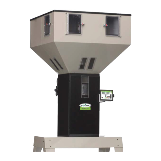
W h a t i s t h e Tr u e B l e n d S B - 4 B l e n d e r ? The TrueBlend SB-4 Blender is a precision gain-in-weight gravimetric batch blender. The ability to precisely control the material blend improves overall quality and reduces material cost. -
Page 15: How It Works: Understanding The Parts Of The Trueblend Sb-4
H o w I t Wo r k s : U n d e r s t a n d i n g t h e Pa r t s o f t h e Tr u e B l e n d S B - 4 Hopper Loader Cover for Vertical Valve Assembly... -
Page 16: How It Works: Trueblend
H o w I t Wo r k s : T h e Tr u e B l e n d The TrueBlend Blender meters and mixes free-flowing plastic granulate (regrind and natural material) and additives. The unit mixes four to six materials, depending on model and con- figuration. -
Page 17: Trueblend Sb-4 System Components
Tr u e B l e n d S B - 4 S y s t e m C o m p o n e n t s The TrueBlend SB-4 Blender is comprised of a number of separate components, each hav- ing a specific function, as described below: TrueBlend SB-4 Controller –... -
Page 18: S P E C I F I C At I O N S
3% color and 2% additive material. † Installed 75 {34} The optional flow control valve will mount inside the chassis in the space of the manual slide valve. Conair Shipping 125 {57} recommends using the optional flow control valve when Voltage total amps mounting the blender on a stand, surge bin or hopper. - Page 19 † Shipping 270 {122} The optional flow control valve will mount inside the chassis in the space of the manual slide valve. Conair Voltage total amps recommends using the optional flow control valve when 115V/1 phase/60 hz mounting the blender on a stand, surge bin or hopper.
- Page 20 † The optional flow control valve will mount inside the chassis in Voltage total amps the space of the manual slide valve. Conair recommends using the optional flow control valve when mounting the 115V/1 phase/60 hz blender on a stand, surge bin or hopper.
- Page 21 The optional flow control valve will mount inside the chassis in the space Shipping of the manual slide valve. Conair recommends using the optional flow Voltage total amps control valve when mounting the blender on a stand, surge bin or hopper.
- Page 22 The optional flow control valve will mount inside the chassis in the space of the 115V/1 phase/60 hz manual slide valve. Conair recommends using the optional flow control valve when mounting the blender on a stand, surge bin or hopper.
- Page 23 The optional flow control valve will mount inside the chassis in the Voltage total amps space of the manual slide valve. Conair recommends using the option- al flow control valve when mounting the blender on a stand, surge bin 115V/1 phase/60 hz or hopper.
- Page 24 400V/3 phase/50 hz † 480V/3 phase/60 hz The optional flow control valve will mount inside the chassis in the space of the manual slide valve. Conair 575V/3 phase/60 hz recommends using the optional flow control valve when Compressed air requirements mounting the blender on a stand, surge bin or hopper.
- Page 25 10.3 † The optional flow control valve will mount inside the 400V/3 phase/50 hz chassis in the space of the manual slide valve. Conair 480V/3 phase/60 hz recommends using the optional flow control valve when 575V/3 phase/60 hz mounting the blender on a stand, surge bin or hopper.
-
Page 26: Specifications: Trueblend
10.3 † 400V/3 phase/50 hz The optional flow control valve will mount inside the chassis in the space of the manual slide valve. Conair 480V/3 phase/60 hz recommends using the optional flow control valve when 575V/3 phase/60 hz mounting the blender on a stand, surge bin or hopper. - Page 27 115V/1 phase/60 Hz 230V/1 phase/50 Hz Specifications may change with- Compressed air requirements out notice, consult with a Conair Discharge valves 90 psi @ 0.2 ft /min. {6 bars @0.09 liters/sec}, 1/4 inch NPT fitting representative for the most current ‡...
- Page 28 (For exam- ple, an output used with an alarm connected to a PC • Remote alarms (compatible with Conair’s Universal Alarm Box) monitoring system.) Capacitance Sensor Connections Remote Alarms Option...
-
Page 29: I N S T A L L A T I O N
S E C T I O N I n s t a l l a t i o n U n p a c k i n g t h e B o x e s ..... 3 - 2 P r e p a r i n g f o r I n s t a l l a t i o n . -
Page 30: Unpacking The Boxes
U n p a c k i n g t h e B o x e s Upon receiving the shipment, always perform a thorough inspection of the contents and compare it the enclosed packing list. Make sure all parts listed are present and that no visi- ble damage exists. -
Page 31: Preparing For Installation
P r e p a r i n g f o r I n s t a l l a t i o n The TrueBlend Blender is easy to install if you plan the location and prepare the mounting area properly. -
Page 32: Preparing To Mount The Blender
NOTE: If your mounting surface does not match the standard bolt patterns available, you will need an adapter. You can make an adapter using the dimensions provided or purchase one from Conair. Contact Conair Parts at 1.800.458.1960 From outside the United States, call 814.437.6861... -
Page 33: Mounting The Control
M o u n t i n g t h e C o n t r o l Mount the control. The HMI operator panel can be mounted on the side of the blender chassis or it can be secured to the blender stand or the processing machine. -
Page 34: Layout Of The Material Hoppers
L a y o u t o f t h e M a t e r i a l H o p p e r s 4 position Position 2 Position 1 & 2 = Main components Position 1 Position 3 & 4 = Additive components Controller location Position 3 Position 4... -
Page 35: Connecting Compressed Air
C o n n e c t i n g C o m p r e s s e d A i r Connect the air hose [A] to the compressed air connection of the unit [B]. Connect a clean, dry compressed air supply to the compressed air con- nection on the blender. -
Page 36: Testing The Installation
S y s t e m C o n f i g u r a t i o n The TrueBlend SB-4 system is a highly flexible and user configurable system. As such, it has the ability to store a significant amount of data to completely describe your particular process application and set-up. -
Page 37: Trueblend Sb-4 Batch Hopper Calibration
Turn power on to the blender. Once the controller display comes on and the blender overview screen is displayed, continue with the calibration. Press the Setup button on the touch screen. The TrueBlend SB-4 setup screen will appear. Press the Batch Hopper button, located at the right side of the screen. The next screen to appear will be the Set up screen for the batch hopper. - Page 38 3 - 1 0 l I n s t a l l a t i o n...
- Page 39 S E C T I O N O p e r a t i o n T h e Tr u e B l e n d S B - 4 O p e r a t o r C o n t r o l Pa n e l ..4 - 2 L o a d i n g M a t e r i a l i n t o t h e Tr u e B l e n d S B - 4 H o p p e r s .
- Page 40 T h e Tr u e B l e n d S B - 4 O p e r a t o r C o n t r o l Pa n e l Home Screen - This is the home screen for the blender. Home Screen - This is the home screen with Job Mode turned on.
-
Page 41: Starting The Blending Process
L o a d i n g M a t e r i a l i n t o t h e Tr u e B l e n d S B - 4 Before the blender can be operated, material must be loaded into the TrueBlend SB-4 mate- rial hoppers. -
Page 42: Touch Panel Interface
The user interface, presented on the touch screen, is a collection of pages or screens which can be used to monitor and control the system. The TrueBlend SB-4 system is designed to work with a variety of configurations and applications. As a result, screen pages will vary, depending upon the configuration of the system. - Page 43 To u c h Pa n e l I n t e r fa c e ( c o n t i n u e d ) • In the lower left corner of the display is an ‘Alarms’ button. This button face will change in color to represent worse case active alarm severity.
- Page 44 To u c h Pa n e l I n t e r fa c e ( c o n t i n u e d ) Screen Navigation Screen navigation is accomplished by pressing buttons visible on the command bars shown at the right hand side of the screen.
- Page 45 To u c h Pa n e l I n t e r fa c e ( c o n t i n u e d ) Page Up – Move up a full page of text in the text box. Page Down –...
-
Page 46: Operating Screens
‘software licensing’ code to be entered in order to contin- ue the boot process. For new installations, this will have been completed by Conair before shipment. The software license codes can be viewed on the <Setup> - <Maintenance> - <License>... - Page 47 O p e r a t i n g S c r e e n s ( c o n t i n u e d ) Home Page The <Home> screen is always displayed after the initial boot screen. For a TrueBlend sys- tem the <Home>...
- Page 48 O p e r a t i n g S c r e e n s ( c o n t i n u e d ) Command Bar: Along the right side of the screen is a command bar that provides navigation to further operational and configuration screens.
- Page 49 O p e r a t i n g S c r e e n s ( c o n t i n u e d ) Job Mode In ‘Job Mode’ the blender will run producing a blend for a set amount of material and then stop.
- Page 50 O p e r a t i n g S c r e e n s ( c o n t i n u e d ) Language – Navigate to the language screen to change display languages. Job – Present the job setup popup window. Totals –...
- Page 51 • 3 – Red - Service – maximum security level - Passcode ‘1111’ - The highest level of security, this level is intended for Conair service personnel or those users who have special training of the blender operation. The pass-codes for each level can be changed in the ‘Setup’ – ‘Panel’ – ‘Security’...
- Page 52 O p e r a t i n g S c r e e n s ( c o n t i n u e d ) Help The Help system provides support documentation for each screen in the user interface. In order to more easily navigate the various help documents, they are organized by Chapter, Section, and Page.
- Page 53 O p e r a t i n g S c r e e n s ( c o n t i n u e d ) Alarms The TrueBlend system contains alarms for each device in the system. There are three levels of alarm severity, Information, General, and Shutdown.
- Page 54 O p e r a t i n g S c r e e n s ( c o n t i n u e d ) Alarm List For each alarm in the alarm list, information fully describes the alarm state and time of occurrence.
- Page 55 O p e r a t i n g S c r e e n s ( c o n t i n u e d ) Logged Alarms The <Logged Alarms> screen is divided into two main sections. The (Alarm Log) section contains the list of logged or historical alarms.
- Page 56 O p e r a t i n g S c r e e n s ( c o n t i n u e d ) Alarm Control: • Press the Alarm button to view the active alarms screen F1 •...
- Page 57 O p e r a t i n g S c r e e n s ( c o n t i n u e d ) Recipe Error List For each alarm in the alarm list, information fully describes the error state. •...
- Page 58 O p e r a t i n g S c r e e n s ( c o n t i n u e d ) Reports The TrueBlend system has a variety of reporting features. It has the capability of generating text based report outputs, continuous logged data output, or remotely connected PC based output.
- Page 59 O p e r a t i n g S c r e e n s ( c o n t i n u e d ) On demand reports are generated the moment the [Run Report] button is pressed. A progress bar will be presented showing the progress of the report generation.
- Page 60 O p e r a t i n g S c r e e n s ( c o n t i n u e d ) • Shift Inventory Report: This report shows the current shift totals and the percentage of each ingredient as con- sumed over the shift.
- Page 61 O p e r a t i n g S c r e e n s ( c o n t i n u e d ) Scheduled Reports Each On Demand text report has the capability of being generated automatically on a peri- odic basis.
- Page 62 O p e r a t i n g S c r e e n s ( c o n t i n u e d ) To generate a scheduled report: In the (Scheduled) section, select the type of report to be generated from the pull- down menu.
- Page 63 O p e r a t i n g S c r e e n s ( c o n t i n u e d ) Logging Data Process data can be logged to files either on the internal drive or a USB thumb drive. Each data record consists of a single line of data that is comma separated.
- Page 64 The PC contains a windows application TBReports provided by Conair. This application will monitor the Ethernet port of the PC for UDP packet data from the blender and add the data to files stored on the PC. The application can then be used to generate comma separated data files that can be used for data analysis.
- Page 65 O p e r a t i n g S c r e e n s ( c o n t i n u e d ) Parameter Options Description Unit Name (4 char String) Identification name of the blender in TBReports. Shift Inventory Report Yes / No Enable the shift inventory output.
- Page 66 O p e r a t i n g S c r e e n s ( c o n t i n u e d ) File Manager The [File Manager] button presents a screen where the operator can view On Demand and Scheduled text reports that have been created.
- Page 67 O p e r a t i n g S c r e e n s ( c o n t i n u e d ) Totals General Information The blending system maintains the total material processed by each component hopper. The component totals are summed together for a system total.
- Page 68 O p e r a t i n g S c r e e n s ( c o n t i n u e d ) • Order Totals: If Order Names is enabled, there is an additional set of totals available. This set of totals is intended to track material usage on a per order basis.
- Page 69 O p e r a t i n g S c r e e n s ( c o n t i n u e d ) Resin Totals The blending system maintains the total material processed by each component hopper. If Resin Names are enabled via setup, then a Resin can be assigned to each component hopper in the Recipe.
- Page 70 O p e r a t i n g S c r e e n s ( c o n t i n u e d ) Recipe The recipe screens are provided to enter the (Production Recipe) or target set values which the blender will attain.
- Page 71 O p e r a t i n g S c r e e n s ( c o n t i n u e d ) Order Names If (Order Names) have been enabled, then a data entry field to enter the next order name will be shown.
- Page 72 O p e r a t i n g S c r e e n s ( c o n t i n u e d ) Command Bar Automatic - Places the Blender into automatic operation. This action requires a valid recipe be entered from the Recipe screen.
- Page 73 O p e r a t i n g S c r e e n s ( c o n t i n u e d ) For additional component hoppers, a [Previous/Next] button is available to view the addi- tional components hoppers.
-
Page 74: Setup Screen
O p e r a t i n g S c r e e n s ( c o n t i n u e d ) Material Calibrate This button will present a popup which will allow the operator to clear component feed rate tables. -
Page 75: Recipe Book
O p e r a t i n g S c r e e n s ( c o n t i n u e d ) Recipe Book The (Recipe Book) is the name given to the list of permanently stored recipes. A maximum of 1000 recipes can be maintained. - Page 76 O p e r a t i n g S c r e e n s ( c o n t i n u e d ) Select Recipe Press the [Select] button to copy the current recipe in the book to the (New Recipe). A con- firmation popup will be presented to confirm the selection.
- Page 77 O p e r a t i n g S c r e e n s ( c o n t i n u e d ) Edit Stored Recipe To edit a stored recipe the operator must have the proper security rights. This is config- urable in the <Setup, Panel, Security>...
- Page 78 O p e r a t i n g S c r e e n s ( c o n t i n u e d ) Resin Selection / Names If resins codes are enabled then for each hopper in the system, a resin data entry field will be presented for the component on the <Recipe>...
- Page 79 O p e r a t i n g S c r e e n s ( c o n t i n u e d ) Loading Monitor and Control This page shows the status of each loader and the pump in the system. The self-loading feature can be independently started and stopped using the [Automatic] and [Stop] buttons.
- Page 80 O p e r a t i n g S c r e e n s ( c o n t i n u e d ) Disabled: Loader body is disabled. Loading to this loader body is not controlled or moni- tored.
- Page 81 O p e r a t i n g S c r e e n s ( c o n t i n u e d ) Loaders This page shows the status of a single loader and the pump in the system. An image for the loader will display the current state of the loader, (Disabled, Enabled, Requesting, Loading, and Dumping).
- Page 82 O p e r a t i n g S c r e e n s ( c o n t i n u e d ) Blowers This page shows the status of the current pump in the system. An image for the pump will display the current state of the pump (Disabled, Enabled, Running, and Idling).
-
Page 83: Setup Screens
S e t u p a n d C o n f i g u r a t i o n Setup is used to configure the TrueBlend SB-4 systems operating parameters - the calibra- tion, the blender model number, number of component bins, batch hopper weight and other parameters. - Page 84 S e t u p S c r e e n s ( c o n t i n u e d ) Component: This device represents the component material hoppers. All control parame- ters for the feed gates and alarm tolerances can be configured. Batch Hopper: This device is the central batch hopper where the component hopper gates feed material.
- Page 85 S e t u p S c r e e n s ( c o n t i n u e d ) S y s t e m D e v i c e This group of screens is used to set system wide operational parameters. This includes sec- tions for the parameters that define the physical configuration of the blender, the methods by which production recipes are entered, and the severity and processing of alarm states.
- Page 86 The [Extruder] button shown on this page is to launch a popup window for configuration of the extrusion control features of a TrueBlendExt system. This will not be discussed in this document. For a TrueBlendExt manual contact a Conair representative. The basic control parameters are:...
- Page 87 The [Extruder] button shown on this page is to launch a popup window for configuration of the extrusion recipe entry features of a TrueBlendExt system. This will not be discussed in this document. For a TrueBlendExt manual contact a Conair representative. The basic recipe parameters are:...
- Page 88 S e t u p S c r e e n s ( c o n t i n u e d ) Relays This page is used to set up the system configurable relays. Not all relays are user config- urable.
- Page 89 S e t u p S c r e e n s ( c o n t i n u e d ) Alarm This page of the setup is concerned with setup and configuration of the alarm system. Each device in the system has the capability of generating a number of alarms.
- Page 90 S e t u p S c r e e n s ( c o n t i n u e d ) Alarm: {Operator} Select the alarm that needs to be changed or viewed. A pulldown menus is provided that lists all of the alarms that are assigned to the selected device. Stop / Manual / Automatic: <various>...
- Page 91 S e t u p S c r e e n s ( c o n t i n u e d ) Pa n e l D e v i c e This group of screens is used to configure the CPU, the touch screen, units, security level, and system date and time.
- Page 92 S e t u p S c r e e n s ( c o n t i n u e d ) Units All units are represented internally the same regardless of what unit types are shown on the display.
- Page 93 S e t u p S c r e e n s ( c o n t i n u e d ) More…: This button is provided to show a popup where the precision of additional unit types can be set. Security This screen sets parameters relevant to the security system.
- Page 94 S e t u p S c r e e n s ( c o n t i n u e d ) Press the [Advanced] button to enter additional parameters. The basic Security settings are: Parameter Default Range Security Description Level For Setup Guest/ Operator/...
- Page 95 S e t u p S c r e e n s ( c o n t i n u e d ) Time This screen is used for setting the systems time and date. Pressing the [Shift] button, a popup is presented where time parameters are available for setting up (3) work shifts.
- Page 96 S e t u p S c r e e n s ( c o n t i n u e d ) ✐ NOTE: The duration of the shifts cannot sum to a value greater than 24 hours. Also the duration of a shift should not overlap another shifts time.
- Page 97 S e t u p S c r e e n s ( c o n t i n u e d ) C o m p o n e n t D e v i c e The component setup screens are used to set parameters that are relevant to an individual material hopper.
- Page 98 S e t u p S c r e e n s ( c o n t i n u e d ) The advanced component control settings are: Parameter Default Range Security Description Large Table Resolution [5:999] Setup/Stop The time difference in milliseconds between entries in (ms) the feed table for large resolution feed rates.
- Page 99 S e t u p S c r e e n s ( c o n t i n u e d ) The basic component alarm settings are: Parameter Default Range Security Description Quantity of Incorrect Feeds [1:10] Service The number of bad gate feeds before a Material Feed Before Alarm Error alarm is generated.
- Page 100 S e t u p S c r e e n s ( c o n t i n u e d ) B a t c h H o p p e r The Batch Weigh Hopper setup screens are used to set parameters that are relevant to the weigh hopper.
- Page 101 S e t u p S c r e e n s ( c o n t i n u e d ) Control This page is for setting up control parameters for the batch weigh hopper. The basic batch hopper control settings are: Parameter Default Range Security Description...
- Page 102 S e t u p S c r e e n s ( c o n t i n u e d ) Advanced: This button will present a popup window where additional less frequently used parameters can be set. Parameter Default Range...
- Page 103 S e t u p S c r e e n s ( c o n t i n u e d ) Calibration This page is for calibration of the batch weigh hopper mounted above the mixing chamber. Calibration is the process by which the tare weight of the hopper is determined.
- Page 104 S e t u p S c r e e n s ( c o n t i n u e d ) Calibration Procedure {Operator / Stop} Press the [Manual Calibrate] button. It is a good idea to re-calibrate the unit after it has been transported and mounted.
- Page 105 S e t u p S c r e e n s ( c o n t i n u e d ) Stand by while the system obtains the Test Weight AD Value. Remove the test weight from the hopper. The displayed hopper weight should return to 0. M i x e r The mixer setup screens are used to set parameters that are relevant to the mixing device.
- Page 106 S e t u p S c r e e n s ( c o n t i n u e d ) The basic mixer control settings are: Parameter Default Range Security Description Mix Time [0:60] Setup The amount of time the mixer motor runs to blend the (sec) material after the batch hopper empties.
- Page 107 Some remote protocols will require an unlock code to enable. This page will configure and setup the various protocols and required hardware. When entering the unlock code, the station identifier will be presented. A Conair represen- tative can use the station identifier code to generate the unlock code. The unlock code must be correctly applied in order to enable the protocol.
- Page 108 S e t u p S c r e e n s ( c o n t i n u e d ) Network Device Sections IPAddress: This screen is for the setup and review of the systems remote network configu- ration.
- Page 109 The Profibus protocol requires the addition of special hardware in order to function. Contact a Conair representative if the protocol is to be implemented. (Continued) O p e r a t i o n l...
- Page 110 S e t u p S c r e e n s ( c o n t i n u e d ) The protocols settings are: Parameter Default Range Security Description Modbus Yes/No Service/ Stop The Modbus protocol does not require an unlock code in order to TCP/IP enable.
- Page 111 Contact a Conair sales or service representative for further information. In order to set up a serial protocol, the port where the protocol will reside must first be cho- sen.
- Page 112 S e t u p S c r e e n s ( c o n t i n u e d ) Email The system has the capability of sending an email whenever an alarm of a set severity occurs. A maximum of 3 recipients can be configured to receive the emails.
- Page 113 ✐ NOTE: The setup of the Microsoft SQL server side is the responsibility of the customers IT depart- ment. Conair does have an SQL Server interface manual which can be used as a guide in this process. ✐...
- Page 114 SQL Database is configured. ✐ NOTE: Conair can provide several pre-built report outputs which can be loaded into the Microsoft SQL Server. These reports provide a variety of means by which material usage data can be seen. These reports require the (BATCHES) data table be enabled.
- Page 115 S e t u p S c r e e n s ( c o n t i n u e d ) The data table settings are: Parameter Default Range Security Description Inventory Data Yes/No Service This setting will enable or disable the connection with the server.
- Page 116 S e t u p S c r e e n s ( c o n t i n u e d ) M a i n t e n a n c e The maintenance area provides a set of screens which enable the operator to perform a series of maintenance features, including backing up the configuration, recipes, licensing, and defaulting the system to factory defaults.
- Page 117 S e t u p S c r e e n s ( c o n t i n u e d ) File Manager This screen allows the operator to save and retrieve various data files to the onboard flash drive, or to an attached USB thumb-drive.
- Page 118 S e t u p S c r e e n s ( c o n t i n u e d ) Access to the USB thumb-drive with an FTP Client is possible with a user login and pass- word of (USB Port 1: Username: conairusb1, Password: conairusb / USB Port 2: Username: conairuSB-4, Password: conairusb).
- Page 119 Also Conair service often will request the configuration files in order to diagnose issues with the system. After performing a retrieval of the configuration, the system will perform a reboot sequence upon returning to the <Home>...
- Page 120 S e t u p S c r e e n s ( c o n t i n u e d ) Manual Control This mode allows the operator to control the component gates valves, the batch hopper dump valve, the alarm claxon, the alarm beacon, the mixing chamber motor, and the mixing chamber dump valve outputs manually.
- Page 121 If the code is invalid or unavailable, the popup window will close and the feature will be disabled. The Station Identifier must be provided to a Conair representative in order to generate the unlock code for the feature. Each unlock code is unique for the touch-panel and the feature.
- Page 122 S e t u p S c r e e n s ( c o n t i n u e d ) S e l f l o a d i n g S e t u p The blender has the capability to provide self-loading. IT will monitor requests for loads from the receiver bodies and then sequence the receiver valves and the blower pump to load material.
- Page 123 S e t u p S c r e e n s ( c o n t i n u e d ) Loader The loader setup screens are used to set parame- ters that are relevant to the loading receiver bod- ies.
- Page 124 S e t u p S c r e e n s ( c o n t i n u e d ) Control This page is used for setting up the loader’s addressing and type settings. Each loader has its own set of settings.
- Page 125 S e t u p S c r e e n s ( c o n t i n u e d ) Time This page is used to configure the times for loading and dumping the receivers. Each loader has its own set of settings.
- Page 126 S e t u p S c r e e n s ( c o n t i n u e d ) Remote Loading The blender can perform load sequencing for loader bodies located on remote blenders. The blenders must be connected via standard Ethernet wiring practices. The following procedure outlines the process for setting up this type of connection.
- Page 127 S e t u p S c r e e n s ( c o n t i n u e d ) The system should now be properly configured. The loading monitor screens can be refer- enced to see the status of the loading process and communications. From the <Home>...
- Page 128 S e t u p S c r e e n s ( c o n t i n u e d ) Diagnostic Devices X20PLC: This device contains diagnostic information for the PLC and touchscreen hard- ware. Batch Hopper: This device contains diagnostic information for the batch hopper’s weigh- ing system and last batch statistics.
- Page 129 S e t u p S c r e e n s ( c o n t i n u e d ) Text Status Indication A text indicator for the slice relates whether the slice is OK (Green) or BAD (Red). If the slice is BAD then the system cannot determine the pre-defined slice at the specified slot address.
- Page 130 S e t u p S c r e e n s ( c o n t i n u e d ) Slice Detail - Connections If the PLC IS NOT in (Test Mode / Automatic) mode, touching the slice graphic, or the slice <Type>...
- Page 131 S e t u p S c r e e n s ( c o n t i n u e d ) This section highlights the status of the batch weighing system and the quality of the batch processing. Info: This page provides information regarding the stability of the batch hopper itself.
- Page 132 S e t u p S c r e e n s ( c o n t i n u e d ) Dosing Rate This page shows the overall average amount of material fed per time for each component hopper.
- Page 133 S e t u p S c r e e n s ( c o n t i n u e d ) Last Feed: • Set: The amount of material the last feed sequence was requesting. • Actual: The actual amount of material the last feed sequence received. •...
- Page 134 4 - 9 6 l O p e r a t i o n...
- Page 135 S E C T I O N M a i n t e n a n c e P r e v e n t a t i v e M a i n t e n a n c e S c h e d u l e ... 5 - 2 P r e v e n t a t i v e M a i n t e n a n c e C h e c k l i s t .
-
Page 136: Preventative Maintenance Schedule
P r e v e n t a t i v e M a i n t e n a n c e S c h e d u l e The TrueBlend SB-4 system contains components that should be verified for proper opera- tion every six months. The integrity of the TrueBlend SB-4 Batch hopper load cell, is important for reliable and accurate control of the system. -
Page 137: Loading Equipment
814 437 6861 To download the most up to date TrueBlend SB-4 software version, contact Conair service. S h u t t i n g O f f i n a n E m e r g e n c y Switch the main switch to off. - Page 138 C h a n g i n g M a t e r i a l i n a B l e n d e r C o m p o n e n t Detachable material hopper procedure For models TB 45 (4 bins) and TB100 (2 bin models) and TB250R (2 bins). All detachable material hoppers are held in place with a captive retainer (screw) attached to the hopper support frame.
-
Page 139: Changing Material In A Blender Component
✒ Tip: A Conair Drain Chute Accessory is available. This allows the discharge valves to be operated in manual mode. Using a “dowel rod” approximately 12 inches long, press vertically into the respec- tive valve opening and raise the plunger cone to allow materials to flow from the material compartments. -
Page 140: Cleaning The Mixer
C l e a n i n g t h e M i x e r CA U T I O N : M i x b l a d e h a z a r d There are two hazards associated with the mix blades. First, the blades are driven with substantial torque. -
Page 141: Testing The Safety Interlock Function
C l e a n i n g t h e M i x e r ( c o n t i n u e d ) Removing material The dispense valve unit is opened and the material runs out of the material hopper through the optional deflector to the collection receptacle. -
Page 142: Calibrating/Adjusting The Sensor
R e m o v i n g a n d I n s t a l l i n g t h e M i x i n g C h a m b e r Remove the mixing chamber by pulling straight out. - Page 143 C a l i b r a t i n g / A d j u s t i n g t h e S e n s o r ( c o n t i n u e d ) Hold a finger over the front of the sensor and make sure that the yellow LED ring illuminates to indicate that the sensor is functioning properly.
-
Page 144: Replacing Pneumatic Cylinder On Vertical Dispense Valve
R e p l a c i n g P n e u m a t i c C y l i n d e r o n Ve r t i c a l D i s p e n s e Va l v e A s s e m b l y Open the cover [3]. -
Page 145: Load Cell Removal And Installation
L o a d C e l l R e m o va l a n d I n s t a l l a t i o n ( M o d e l s T B 0 4 5 & T B 1 0 0 ) WA R N I N G : E l e c t r i c S h o c k High voltages can cause life-threatening currents in the body and injury from elec- tric shock. -
Page 146: Weigh Bin Mount Installation And Adjustment
We i g h B i n M o u n t I n s t a l l a t i o n a n d A d j u s t m e n t ( M o d e l s T B 0 4 5 & T B 1 0 0 ) Follow these steps to install and adjust the weigh bin and/or the weigh bin mount on TrueBlend models TB45 and TB100. - Page 147 We i g h B i n M o u n t I n s t a l l a t i o n a n d A d j u s t m e n t ( M o d e l s T B 2 5 0 , T B 5 0 0 , T B 9 0 0 ) The weigh bin needs to set freely in the bottom of the slots and the hoses are to be connect- ed in the quick disconnects.
-
Page 148: Load Cell Removal
L o a d C e l l R e m o va l ( M o d e l s T B 2 5 0 , T B 5 0 0 , T B 9 0 0 ) WA R N I N G : E l e c t r i c S h o c k High voltages can cause life-threatening currents in the body and injury from elec- tric shock. - Page 149 L o a d C e l l I n s t a l l a t i o n ( M o d e l s T B 2 5 0 , T B 5 0 0 , T B 9 0 0 ) WA R N I N G : E l e c t r i c S h o c k High voltages can cause life-threatening currents in the body and injury from elec- tric shock.
-
Page 150: Load Cell Installation
L o a d C e l l I n s t a l l a t i o n ( M o d e l s T B 2 5 0 , T B 5 0 0 , T B 9 0 0 ) ( c o n t i n u e d ) If the stop bolt [4] and lock nut [5] were loosened during removal or installation,... -
Page 151: Tr O U B L E S H O O T I N G
S E C T I O N Tr o u b l e s h o o t i n g B e f o r e B e g i n n i n g ..... . . 6 - 2 A Fe w Wo r d s o f C a u t i o n . -
Page 152: Before Beginning
Verify that you have the user manuals for the equipment located upstream and down- stream from the TrueBlend SB-4 system. Solving problems related to material coveyed to the TrueBlend SB-4 or due to poor extrusion or injection quality may require trou- bleshooting malfunctions or incorrect operating procedures on other pieces of equip- ment on the production line. -
Page 153: How To Identify The Cause Of A Problem
H o w t o I d e n t i f y t h e C a u s e o f a P r o b l e m To find the cause of an alarm, on each screen in the system the [Alarms] key appears in the lower left corner of the display. -
Page 154: Alarms
A l a r m s The ‘ALARM’ key allows the operator to view, silence and acknowledge TrueBlend SB-4 system alarms. Possible alarms for the system include: Blender Alarms The blender alarm screen displays parameters used to generate alarms for the TrueBlend SB-4 Blender. -
Page 155: Basic Alarms
B a s i c A l a r m s Alarm Possible Cause Solution Message: Batch Hopper is not dump- Batch weigh hopper exit gate is not Ensure the batch hopper exit gate fully ing. opening and closing properly, and all the opens and closes properly. - Page 156 B a s i c A l a r m s ( c o n t i n u e d ) Alarm Possible Cause Solution Message: Component hopper low on Occurs ONLY with optional component Check the component hopper to be material.
- Page 157 B a s i c A l a r m s ( c o n t i n u e d ) Alarm Possible Cause Solution Message: X20 slice is bad. Power or Communications has been lost Occurs if +24vdc is removed, or X2X to the PLC Slices in the blender electri- network communication is lost from cal panel.
-
Page 158: Replacing Fuses
Located inside the TrueBlend SB-4 electrical control panel are fuses for the AC line, FU1, and the power supply output side, FU2 and FU3. To replace a blown fuse: Disconnect and lockout the main power. -
Page 159: Replacing Load Cells
Remove the material from the TrueBlend SB-4 extruder hopper. Disconnect the load cell wiring that extends into the control box (see wiring dia- gram). Remove the two screws that are used to mount the TrueBlend SB-4 extruder hopper to the load cell. Remove the TrueBlend SB-4 extruder hopper. - Page 160 6 - 1 0 l Tr o u b l e s h o o t i n g...
-
Page 161: Appendix
We ’ r e H e r e t o H e l p Conair has made the largest investment in customer support in the plastics industry. Our service Additional manuals and prints for experts are available to help with any problem you might have installing and operating your equip- your Conair equipment may be ment. -
Page 162: Equipment Guarantee
E q u i p m e n t G u a r a n t e e Conair guarantees the machinery and equipment on this order, for a period as defined in the quotation from date of shipment, against defects in material and workmanship under the nor- mal use and service for which it was recommended (except for parts that are typically replaced after normal usage, such as filters, liner plates, etc.). -
Page 163: Retrofit Control Blender Start Up Procedures
R e t r o f i t C o n t r o l B l e n d e r S t a r t U p P r o c e d u r e s When the TrueBlend Controller is used in retrofit replacement applications, follow the initial setup procedure below to ensure your blender will run at its optimum accuracy. -
Page 164: Appendix
Mark your location of hole that will need to be drilled and tapped (see the illus- available from tration on the next page for your particular blender size). Conair. (Part # 61126101) Remove the level sensor (noting location of adjustment and sensor face), mixing... - Page 165 H o l e L o c a t i o n s f o r B l o w - O f f K i t A p p e n d i x l C - 2...
-
Page 166: Appendix
I n s t a l l i n g A u t o m a t i c F l o w C o n t r o l Va l v e ( O p t i o n ) Disconnect and lockout the main power supply, and the air supply from the blender. -
Page 167: Installing Dry Air Blanket (Option
I n s t a l l i n g D r y A i r B l a n k e t ( O p t i o n ) Isolation valves Inlet air adaptor Disconnect and lockout the main power supply, and the air supply from the blender. - Page 168 D - 3 l A p p e n d i x...
Need help?
Do you have a question about the TrueBlend SB-4 and is the answer not in the manual?
Questions and answers
I have an older conair trublend where the dump cylinder is between the material hoppers how do i access the cylinder?
To access the dump cylinder on a Conair TrueBlend SB-4 when it is located between the material hoppers, you need to access it from outside of the valve through the respective blender clean-out door.
This answer is automatically generated