Table of Contents
Advertisement
Quick Links
Download this manual
See also:
User Manual
TRBOnet Swift A200
World HQ
US Office
Neocom Software
Neocom Software
8th Line 29, Vasilyevsky Island
15200 Jog Road, Suite 202
St. Petersburg, 199004, Russia
Delray Beach, FL 33446, USA
Radio-over-IP Gateway
User Manual
Internet
Email: info@trbonet.com
WWW.TRBONET.COM
Telephone
EMEA: +44 203 608 0598
Americas: +1 872 222 8726
APAC: +61 28 6078325
Advertisement
Table of Contents

Related Manuals for TRBOnet Swift A200


Summary of Contents for TRBOnet Swift A200
-
Page 1: User Manual
Radio-over-IP Gateway TRBOnet Swift A200 User Manual World HQ US Office Internet Telephone Neocom Software Neocom Software EMEA: +44 203 608 0598 8th Line 29, Vasilyevsky Island 15200 Jog Road, Suite 202 Email: info@trbonet.com Americas: +1 872 222 8726 St. Petersburg, 199004, Russia Delray Beach, FL 33446, USA WWW.TRBONET.COM... - Page 2 This document is for informational purposes only. Neocom software, Ltd offers no warranties, express or implied, in this document. Neocom and the Neocom logo, TRBOnet and the TRBOnet logo are either registered trademarks or trademarks of Neocom software, Ltd. MOTOROLA, MOTO, MOTOROLA SOLUTIONS and the Stylized M logo are trademarks or registered trademarks of Motorola Trademark Holdings, LLC.
-
Page 3: Table Of Contents
Contents Introduction ................................1 About This Document ........................1 About TRBOnet Swift .........................1 Contacts ..............................1 About TRBOnet Swift A200 ...........................2 Features ..............................2 Capabilities ............................2 Restrictions ............................3 Package Contents ..........................3 Specification ............................4 Design ..............................5 Connectors ............................6 LED Indication ............................7 Setup and Connection ............................8 MOTOTRBO Mode ..........................8... -
Page 4: Introduction
The information in this document is intended for engineers responsible for building MOTOTRBO radio networks and programming two-way radios for end users. The document describes in detail how to connect, set up, and maintain the TRBOnet Swift A200 hardware radio-over-IP gateway. -
Page 5: About Trbonet Swift A200
About TRBOnet Swift A200 TRBOnet Swift A200 (also referred to as the "A200 gateway") is a hardware radio-over- IP gateway designed to interface your TRBOnet Server to a MOTOTRBO or non- MOTOTRBO control (donor) radio, or a MOTOTRBO repeater in the analog or digital mode. -
Page 6: Restrictions
3. We do not recommend to install any Swift IP Gateways in the same subnet as trunked repeaters (applies to Capacity Plus and Linked Capacity Plus). Package Contents The package contents of TRBOnet Swift A200 include the following items: Table 1: TRBOnet Swift A200 package contents Item... -
Page 7: Specification
Radio connection interfaces USB (wired), NRF (wireless) MOTOTRBO Audio (wired) Non-MOTOTRBO Inputs/outputs Open collector Output type 100 mA Output current, max 12 V Input voltage, max TRBOnet Enterprise/PLUS of version 5.2.5 and higher is required. TRBOnet Swift A200 – User Manual... -
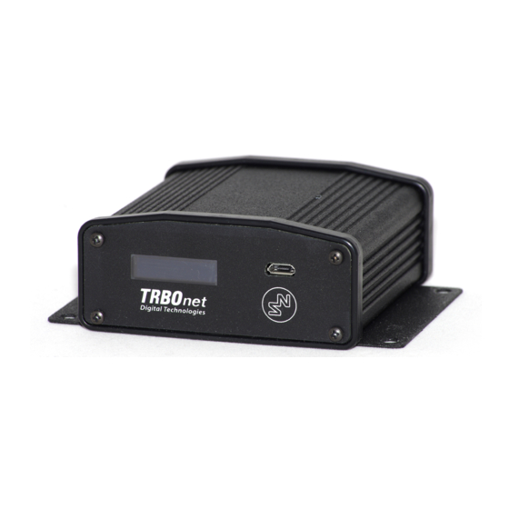
Page 8: Design
About TRBOnet Swift A200 Design FRONT PANEL OLED display that shows the connection status and self-check information. Micro-USB port to connect the device to a computer using the programming cable. REAR PANEL DC power inlet. Audio Input and Audio Output to connect a non-MOTOTRBO two-way radio. -
Page 9: Connectors
Table 3: I/O connector pinout I/O Connector Power (GND) Power (+12V) Input (IN7) Output (OUT7) Input/output (IO6) Input/output (IO5) Input/output (IO4) Input/output (IO3) Input/output (IO2) Input/output (IO1) UART input, 5V (RX) UART output, 5V (TX) TRBOnet Swift A200 – User Manual... -
Page 10: Led Indication
Flashing icon: The radio is not connected or powered off. Radio TX Radio RX IP connection Digits near the icon: The number of connected TRBOnet servers. Flashing icon: the A200 gateway is not connected to an IP network. Activity on the IP connection Wireless connection to the radio... -
Page 11: Setup And Connection
MOTOTRBO Mode To prepare TRBOnet Swift A200 for operation in the MOTOTRBO mode, follow the steps in Table 6. Table 6: High-level steps to prepare TRBOnet Swift A200 for operation in the MOTOTRBO mode Step Refer to: Update the firmware and configure your A200 3.1.1 Configuring the A200... - Page 12 Configuring the A200 Gateway To configure the A200 gateway: Launch TRBOnet Swift CPS. In the main window, select USB as an interface for device programming at the bottom (Figure 1). Connect the programming cable to the micro-USB port of the A200 gateway and to a USB port of your computer.
- Page 13 The configuration settings appear in a separate tab. Click Network Settings in the left panel. Figure 4: Configuring the IP network settings of Swift A200 In the right panel, specify the following settings: IP Address: The IP address assigned to your A200 gateway.
- Page 14 It is important to specify the same NRF connection settings in the configuration of the option board installed inside the radio. (Optional) If you need to display the states of I/O pins in the TRBOnet software tools, click I/O Settings in the left panel.
- Page 15 Orient the flex cable (supplied in the delivery kit) so that it contacts face the option board. Secure the connector latch to the flex cable. Figure 7: Connecting the flex cable to the option board Connect the flex cable from the option board to the main board connector. TRBOnet Swift A200 – User Manual...
- Page 16 Setup and Connection Figure 8: Connecting the option board to the main board of the radio Align the option board to the mounting holes ensuring that the flex tabs are against the chassis alignment posts. Using a T6 TORX™ driver, tighten the three screws to 0.28 N-m (2.5 lbs-in) to secure the option board to the chassis.
- Page 17 Power off the radio. Connect the programming cable to the radio and to a USB port of your computer. Power up the radio. Launch TRBOnet Swift CPS on your computer. In the main window, select USB as the programming interface (Figure 1, page 9).
- Page 18 Setup and Connection Wired (USB) connection with the radio For the wired connection between the radio and A200 gateway, use the USB cable supplied with the A200 gateway. Note: Before connecting the A200 gateway to a MOTOTRBO two-way radio with the USB cable, power off the radio and make sure that the A200 gateway is disconnected from the power supply.
-
Page 19: Non-Mototrbo Mode
Non-MOTOTRBO Mode To prepare TRBOnet Swift A200 for operation in the non-MOTOTRBO mode, follow the steps in Table 7. Table 7: High-level steps to prepare TRBOnet Swift A200 for operation in the non-MOTOTRBO mode Step Refer to: Assemble the service cable. - Page 20 Setup and Connection Table 9: Audio cable – required links Audio cable (wires) Radio connector pin (function) Audio In RX AUDIO Audio Out EXT MIC AUDIO (TX AUDIO) Ground AUDIO GND (Optional) Add wires between the Micro-Fit plug and the radio connector plug to implement additional features.
- Page 21 Launch TRBOnet Swift CPS. In the main window, select USB as an interface for device programming at the bottom (Figure 1, page 9). Connect the programming cable to the micro-USB port of Swift A200 and to a USB port of your computer.
- Page 22 If any I/O pins are connected by external hardware, configure the A200 gateway to send the states of these pins to TRBOnet software. For each I/O pin connected by external hardware, expand the menu and select the logical pin in TRBOnet: ...
-
Page 23: Power Supply
When all connections are done, connect the A200 gateway and external hardware to the power supply. Then power up the radio. Power Supply This section describes how to connect the A200 gateway to the source of +12V DC (recommended) or to an AC power supply. TRBOnet Swift A200 – User Manual... - Page 24 Setup and Connection 3.3.1 DC Power Supply To power the A200 gateway from a DC power source, use the Micro-Fit connector supplied in the delivery kit. The Micro-Fit plug and the wires are connected as follows: the red wire links contact 2 (+12V) and the black wire links contact 1 (GND). Figure 15: Micro-Fit contact positions To connect your A200 gateway to a DC power source: Insert the Micro-Fit plug into the I/O jack on the rear panel of the A200...
-
Page 25: Trbonet Configuration
TRBOnet Configuration This section describes how to configure TRBOnet software so that the operator could see and manage the physical I/O pins of the A200 gateway. In the example below, the A200 gateway is connected to a MOTOTRBO radio through USB and has three input pins and two output pins connected to external hardware (Figure 16). -
Page 26: Trbonet Enterprise/Plus Configuration
TRBOnet Enterprise (PLUS) Server configuration (Figure 18). Figure 18: Registering Swift A200 as a radio system Launch the TRBOnet Dispatch Console and click Voice Dispatch in the left pane. If registered correctly, your A200 gateway appears on the Radio Interface tab with the green (“connected”) icon (Figure 19). - Page 27 (also ON and OFF by default). If necessary, double-click the value in the second column and enter a custom name of the pin state. In the Status field, select Alarm for the TRBOnet Dispatch Console operator to see an alarm box when the given pin state is detected.
- Page 28 The pin states appear in a popup window: Figure 22: Pin states The temperature is measured inside the unit and transmitted to TRBOnet by default, no additional configuration is required. The coolers are missing (“No data”). Input and output pins appear with their custom names. The input pin states are read- only.
-
Page 29: Trbonet Watch Configuration
Figure 23: Changing the output pin states TRBOnet Watch Configuration I/O pins of the A200 gateway are supported in TRBOnet Watch 2.5 and later versions. In this example, the A200 gateway is registered as a radio system in the TRBOnet Watch server configuration (Figure 24). - Page 30 specified in the A200 gateway configuration (Figure 17, page 22). After you apply the changes, launch the TRBOnet Watch console and click Live Monitor in the left pane. You can see the states of the connected A200 gateway pins on the Diagnostics tab and on the Physical GPIO Pins tab.
-
Page 31: Maintenance
Remove the screws and pull the front panel from the unit. Remove the seal. Press the jacks on the rear panel to pull the board out of the unit. Unlock the microSD card holder by pulling it in the front panel’s direction. TRBOnet Swift A200 – User Manual... - Page 32 Maintenance Lift the card holder and remove the microSD card. Insert a replacement microSD card. Ensure that the golden contacts of the memory card face the contacts of the microSD card holder. Put down and lock the card holder, pulling it in the rear panel’s direction. Insert the board inside the unit, assemble the seal and the front panel.
Need help?
Do you have a question about the Swift A200 and is the answer not in the manual?
Questions and answers