Table of Contents
Advertisement
Quick Links
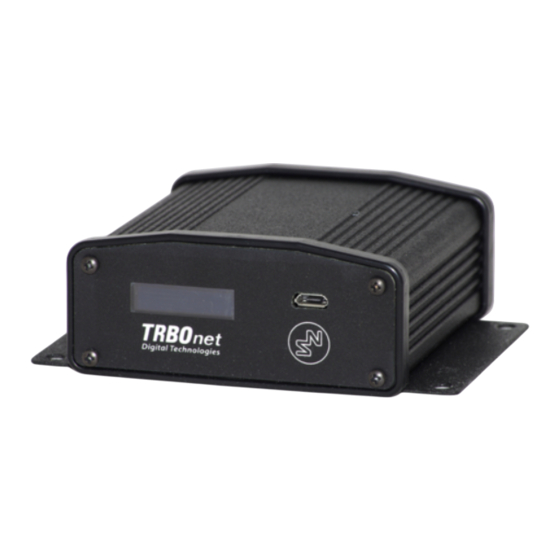
TRBOnet Swift A200
World HQ
US Office
Neocom Software
Neocom Software
8th Line 29, Vasilyevsky Island
15200 Jog Road, Suite 202
St. Petersburg, 199004, Russia
Delray Beach, FL 33446, USA
Radio-over-IP Gateway
User Manual
Internet
Email: info@trbonet.com
WWW.TRBONET.COM
Telephone
EMEA: +44 203 608 0598
Americas: +1 872 222 8726
APAC: +61 28 6078325
Advertisement
Table of Contents

Related Manuals for TRBOnet Swift A200


Summary of Contents for TRBOnet Swift A200
-
Page 1: User Manual
Radio-over-IP Gateway TRBOnet Swift A200 User Manual World HQ US Office Internet Telephone Neocom Software Neocom Software EMEA: +44 203 608 0598 8th Line 29, Vasilyevsky Island 15200 Jog Road, Suite 202 Email: info@trbonet.com Americas: +1 872 222 8726 St. Petersburg, 199004, Russia Delray Beach, FL 33446, USA WWW.TRBONET.COM... - Page 2 This document is for informational purposes only. Neocom software, Ltd offers no warranties, express or implied, in this document. Neocom and the Neocom logo, TRBOnet and the TRBOnet logo are either registered trademarks or trademarks of Neocom software, Ltd. MOTOROLA, MOTO, MOTOROLA SOLUTIONS and the Stylized M logo are trademarks or registered trademarks of Motorola Trademark Holdings, LLC.
-
Page 3: Table Of Contents
Contents Introduction ................................1 About This Document ........................1 About TRBOnet Swift .........................1 Contacts ..............................1 About Swift A200 ..............................2 Features ..............................2 Capabilities ............................2 Restrictions ............................3 Delivery Kit ............................3 Design ..............................4 Connectors ............................5 LED Indication ............................6 Acronyms ...............................7 Setup and Connection ............................8 MOTOTRBO Mode ..........................8 Non-MOTOTRBO Mode ........................ -
Page 4: Introduction
The information in this document is intended for engineers responsible for building MOTOTRBO radio networks and programming two-way radios for end users. The document describes in detail how to connect, set up, and maintain the TRBOnet Swift A200 hardware radio-over-IP gateway. -
Page 5: About Swift A200
A gateway between a radio channel and an IP network A radio connected to Swift A200 can transfer voice and data to all connected TRBOnet Servers over IP. Swift A200 performs no encryption of the transferred voice and data traffic. -
Page 6: Restrictions
3. We do not recommend to install any Swift IP Gateways in the same subnet as trunked repeaters (applies to Capacity Plus and Linked Capacity Plus). Delivery Kit TRBOnet Swift A200 delivery kit includes accessories listed in Table 1. Table 1: TRBOnet Swift A200 delivery kit Item... -
Page 7: Design
Audio Input and Audio Output to connect a non-MOTOTRBO two-way radio. Micro-Fit 3mm pitch connector to connect a non-MOTOTRBO radio, a 12V DC power supply, and external hardware. LAN port. USB port to connect a MOTOTRBO radio. TRBOnet Swift A200 – User Manual... -
Page 8: Connectors
About Swift A200 Connectors Table 2: I/O connector pinout I/O Connector Power (GND) Power (+12V) Input (IN7) Output (OUT7) Input/output (IO6) Input/output (IO5) Input/output (IO4) Input/output (IO3) Input/output (IO2) Input/output (IO1) UART input, 5V (RX) UART output, 5V (TX) -
Page 9: Led Indication
Radio RX IP connection Digits near the icon: The number of connected TRBOnet servers. Flashing icon: Swift A200 is not connected to an IP network. Activity on the IP connection Wireless connection to the radio USB connection to the radio Memory card Flashing icon: The memory card is not detected. -
Page 10: Acronyms
About Swift A200 Acronyms This section lists all abbreviations used in this document. Table 4: Acronyms Acronym Description Alternating current Customer Programming Software Decibel Direct current Gigabyte Ground GPIO Input/output Generic Pin Global System for Mobile Communications Input/output Internet Protocol... -
Page 11: Setup And Connection
TRBOnet Swift CPS software tool on your computer. Then set up and connect your Swift A200 for operation in the preferred mode. Find the details in the following sections: 3.1 MOTOTRBO Mode (page 8) ... - Page 12 Launch TRBOnet Swift CPS. In the main window, select USB as an interface for device programming at the bottom (Figure 1). Connect the programming cable to the micro-USB port of Swift A200 and to a USB port of your computer. Figure 1: Selecting the USB connection for programming...
- Page 13 Figure 3: Updating firmware on Swift A200 connected through USB To open the configuration of your Swift A200, click the Read button, or open the Device menu and click Read. If you use the LAN connection, the Read LAN window appears. Specify the IP address of your Swift A200 and click Read.
- Page 14 I/O Settings in the left panel. Figure 5: Configuring I/O pins In the right panel, configure the I/O pins of Swift A200 that are connected to external hardware (Figure 5). For each connected I/O pin, expand the menu and select the logical pin in TRBOnet: ...
- Page 15 To save the configuration on your Swift A200, click the Write button or open the Device menu and click Write. 3.1.2 Installing the Option Board The delivery kit includes an option board that you need to install into a MOTOTRBO radio.
- Page 16 Setup and Connection Figure 8: Connecting the option board to the main board of the radio Align the option board to the mounting holes ensuring that the flex tabs are against the chassis alignment posts. Using a T6 TORX™ driver, tighten the three screws to 0.28 N-m (2.5 lbs-in) to secure the option board to the chassis.
- Page 17 Connecting Swift A200 to the Radio When all configuration settings are made, connect your Swift A200 to the radio and to the local IP network. The LAN port is located on the rear panel of Swift A200. Wireless (NRF) connection with the radio...
- Page 18 Figure 10: The radio cable Connect the cable to the USB connector on the rear panel of Swift A200 and to the rear accessory connector of the radio. Note: Once you have reconfigured the radio and/or option board, disconnect the programming cable from the radio and reboot by powering off and on both the Swift A200 and the radio.
-
Page 19: Non-Mototrbo Mode
Non-MOTOTRBO Mode To prepare TRBOnet Swift A200 for operation in the non-MOTOTRBO mode, follow the steps in Table 7Table 6. Table 7: High-level steps to prepare TRBOnet Swift A200 for operation in the non-MOTOTRBO mode Step Refer to: Assemble the service cable. - Page 20 Setup and Connection Table 9: Audio cable – required links Audio cable (wires) Radio connector pin (function) Audio In RX AUDIO Audio Out EXT MIC AUDIO (TX AUDIO) Ground AUDIO GND (Optional) Add wires between the Micro-Fit plug and the radio connector plug to implement additional features.
- Page 21 Launch TRBOnet Swift CPS. In the main window, select USB as an interface for device programming at the bottom (Figure 1, page 9). Connect the programming cable to the micro-USB port of Swift A200 and to a USB port of your computer.
- Page 22 “Analog RoIP Gateway”. d. On the Update to menu, select the latest firmware version. Click Update. To open the configuration of your Swift A200, click the Read button, or open the Device menu and click Read. If you use the LAN connection, the Read LAN window appears. Specify the IP address of your Swift A200 and click Read.
- Page 23 To lower the level of the input signal from a non-MOTOTRBO radio, consider setting Input for Audio to IN2. Figure 14: Configuring the audio signal To save the configuration to your Swift A200, click the Write button, or open the Device menu and click Write. 3.2.3...
-
Page 24: Power Supply
A200 accordingly, connect your Swift A200 to the radio and to external hardware (if necessary). Note: Before connecting Swift A200, make sure that the radio is powered off and that Swift A200 and all external hardware (if any to be connected) is disconnected from the power supply. - Page 25 3.3.2 AC Power Supply The AC power cable is not supplied with Swift A200. To power Swift A200 from an external AC power source, use any power cable with the 5.5mm x 2.1 mm DC plug and the AC/DC adaptor with the DC output of +12V (positive polarity) and the input AC voltage recommended for your region.
-
Page 26: Trbonet Configuration
This section describes how to configure TRBOnet software so that the operator could see and manage the physical I/O pins of Swift A200. In the example below, Swift A200 is connected to a MOTOTRBO radio through USB and has three input pins and two output pins connected to external hardware (Figure 16). -
Page 27: Trbonet Enterprise/Plus Configuration
TRBOnet Enterprise/PLUS Configuration I/O pins of Swift A200 are supported in TRBOnet Enterprise (PLUS) 4.8.1.1008 and later versions. In this example, Swift A200 is registered as a radio system in the TRBOnet Enterprise (PLUS) server configuration (Figure 18). Figure 18: Registering Swift A200 as a radio system Launch the TRBOnet Dispatch Console and click Voice Dispatch in the left pane. - Page 28 Under Control states, select the logical input pins that you have mapped in the configuration of your Swift A200 (Figure 17, page 23). Do not select pin 0. For each selected pin: Double-click the value in the Name field and enter a descriptive pin name.
- Page 29 (ON and OFF under Outputs in Figure 22). Or, the operator can right-click the green icon in the PTT box of Swift A200 and change the output pin states from the popup menu (Figure 23).
-
Page 30: Trbonet Watch Configuration
Figure 23: Changing the output pin states TRBOnet Watch Configuration I/O pins of Swift A200 are supported in TRBOnet Watch 2.5 and later versions. In this example, Swift A200 is registered as a radio system in the TRBOnet Watch server configuration (Figure 24). - Page 31 Swift A200 configuration (Figure 17, page 23). After you apply the changes, launch the TRBOnet Watch console and click Live Monitor in the left pane. You can see the states of connected Swift A200 pins on the Diagnostics tab and on the Physical GPIO Pins tab.
-
Page 32: Maintenance
Note: Use the recommended battery type. Batteries that look similar may differ in voltage. Memory Card Replacement Swift A200 is equipped with a 4 Gb microSD memory card. If necessary, you can replace the memory card as described below. To replace the memory card: Disconnect the unit from the power supply. - Page 33 Insert the board inside the unit, assemble the seal and the front panel. Tighten the screws to secure the front panel to the unit. Note: The maximum supported memory size of a microSD card is 32 Gb. TRBOnet Swift A200 – User Manual...
Need help?
Do you have a question about the Swift A200 and is the answer not in the manual?
Questions and answers