Table of Contents
Advertisement
Quick Links
Advertisement
Table of Contents

Related Manuals for PR Lighting XLED 300 Beam


Summary of Contents for PR Lighting XLED 300 Beam
- Page 1 XLED 300 Beam PR-8115 The user manual contains important information about the safe installation and use of a projector. Please read and follow these instructions carefully and keep the manual in a safe place for future reference. PR LIGHTING LTD.
-
Page 2: Table Of Contents
INDEX 1. SAFETY AND WARNINGS ………………………………………………………………………………… 2. INSTUCTIONS …………………………………………………………………………………………… ……………………………………………………………………… CLEANING AND MAINTENANCE ● TROUBLESHOOTING ……………………………………………………………………………………… ● ……………………………………………………………………………………………… 3. APPEARANCE 4. INSTALLATION ……………………………………………………………………………………………… …………………………………………………………………………………………………… RIGGING ● POWER CONNECTIONS ………………………………………………………………………………… ● ………………………………………………………………………… DMX CONTROL CONNECTIONs ● DMX TERMINATOR ………………………………………………………………………………………… ● …………………………………………………………………………… 5. -
Page 3: Safety And Warnings
1. SAFETY AND WARNINGS NOTE Before a projector’s installation, power-on, operation and maintenance, please carefully read the safety information hereinafter! The following safety signs are used in the user manual. User Electrical Goggles Protective High Warning Flames Manual shock Gloves Temperature When unpacking , check if there is transportation damage before using the projector. -
Page 4: Instuctions
There are safety cord holes at the bottom of the base of a projector. In view of safety, please run the safety ● cord supplied through the safety cord holes for safety support. Before any installation, maintenance and cleaning work, please ensure the projector is disconnected from ●... -
Page 5: Troubleshooting
TROUBLESHOOTING ● PROBLEM ACTION Check the fuse on the power socket. The projector doesn’t switch on Check the lamp. The lamp is on but the projector doesn’t respond Make sure that the fixture’s start address is right to the controller Replace or repair the XLR signal cable. -
Page 6: Installation
4. INSTALLATION RIGGING ● Before moving a projector, Please lock Pan and Tilt. Before its operation, please unlock them. It’s forbidden to run a projector with power while it is locked Safety Cord Clamp WARNING: Please run the safety cord through safety hole and make sure that the cord is property secured. -
Page 7: Dmx Control Connections
DMX CONTROL CONNECTION: ● Connection between controller and projector and between one projector and another must be made with a twin-screened cable, with each wire having at least a 0.5mm in diameter. Connection to and from the projector is via cannon 5 pin (which are included with the projector) or 5 pin XLR plugs and sockets. -
Page 8: Setup And Configuration
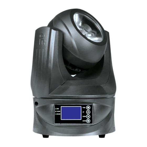
5. SETUP AND CONFIGURATION Front Panel Operation ● Front Panel with Wireless Control Function Front Panel without Wireless Control Function Projector configuration can be set conveniently via push button and LCD display. Launch the projector and press button ENTER for more than 2 seconds to unlock the panel, the LCD will show the function menu of the projector, each main menu has its submenus and each submenu has a specific function. -
Page 9: Dmx Wirelsess Control
DMX WIRELESS CONTROL (If the projector has the function) ● The projector has wireless control function with wireless receiver module and antenna for remote control. The setup of it is below: Enter into the projector’s menu. Select the menu “Config Settigns” via the bottoms of UP and DOWN Select DMX control Mode---- Wireless First (Note: do not select XLR ONLY),then wireless indication in the front panel will be on, meaning wireless control function is activated. -
Page 10: Operation Menu
6. OPERATION MENU level menu level menu level menu level menu Standard:1~495 DMX Address Extended :1~491 Reset Are You Sure DMX Mode Standard 18 (Default:Standard 18) Extended 22 Loss of DMX Normal Time Out (Default: Normal Time Out) Hold Last Value XLR First XLR Only Wireless Mode... - Page 11 Y Hall Ok/Er Self Test Green Blue White Lamp R&G G&B R&B R&G&B Pan Location 0-255 0-127Stop Test Mode 128-191Forward Rotation from slow to Pan Rotaing 0-255 fast 192-255 Reverse Rotation from slow to fast Tilt Location 0-255 0-127Stop 128-191Forward Rotation from slow to Tilt Rotaing 0-255...
-
Page 12: Dmx Protocol
7. DMX PROTOCOL Standard Extended Function Description mode mode Strobe 001-127 Pulse strobe from slow to fast 128-255 Strobe from slow to fast Dimmer 000-255 Linear Dimming 0%-100% Dimming fine 000-255 Dimming in 16 bit Dimming Speed 000-255 Dimming from slow to fast ColorTemperature 001-255 CT linear adjustment from low to high... -
Page 13: Led Indication
8. LED INDICATION DMX signal OK DMX indication No DMX signal Flash DMX signal error Linked with a transmitter Not linked with any transmitter W-DMX indication Being linked with a transmitter or losing link with it or without Flash any wireless signal Sound Control OK Sound control indication Sound Control Off... - Page 14 CONTROL: DMX512, 3-pin and 5-pin interfaces 18channels in standard mode and 22channels in extended mode Master/Slave Mode Stand Alone Mode, Preset Memory, Test Mode and Single Scene Mode OTHER FUNCTIONS: Pan: 720°or 360° and endless rotation; Tilt: 270° and endless rotation; Touch buttons ,LCD display with brightness and contrast adjustable Sound control DMX 512 wireless control...
- Page 15 SIZES: LIGHT OUTPUT: 6204 1551 4.7°(1/2)lux 1.5m 0.5m 0.5m 1.5m DISTANCE( m ) DIAMETER( m ) 0.42 0.83 1.25 1.66 2.08 2.49 15/20...
-
Page 16: Circuit Diagram And Pcb Connections
10. CIRCUIT DIAGRAM AND PCB CONNECTIONS CIRCUIT DIAGRAM ● 16/20... -
Page 17: Pcb Connections
PCB CONNECTIONS ● Signal Output Power PWM output Wireless Signal input Thermal Switch Pan Encoder Tilt Magnet Sensor Tilt Encoder Tilt Motor Signal Output Power Signal input Pan Motor Pan Magnet Sensor 17/20... - Page 18 LED Lamp White Power Thermal Resisitor LED Lamp Red LED Lamp Green LED Lamp Blue Signal Input LED Lamp White(-) 6 LED Lamp Blue(+) LED Lamp White(+) 7 LED Lamp Green(-) LED Lamp Red(-) LED Lamp Green(+) LED Lamp Red (+) 9 Thermal Switch LED Lamp Blue(-) 18/20...
-
Page 19: Component Order Codes
11. COMPONENT ORDER CODES Name Code Number Remarks Power Switch 192010180A Lens 070070059 φ94×55mm Fuse 270041037 φ5.2×20mm 250V 3.15A Pan & Tilt Belt 290151337 HTD-297-3M 7020 Fan 030060087 MGT7012HB-W20 4010 Fan 030060093 HA4010V4-000C-999 Pan & Tilt Motors 030040175 42×42×38-φ5×19 LCD Display 230060505 Pan &... - Page 20 1582 Xingye Avenue, Nancun Pany Guangzhou, 511442 China TEL: +86-20-3995 2888 PR lighting will try its best to offer accurate and overall information about a product’s technical data. Any changes won’t be notified if necessary. Patented Products. Counterfeiting Will be Prosecuted! P/N: 320020391 Version: 20151201 (Preliminary)...
Need help?
Do you have a question about the XLED 300 Beam and is the answer not in the manual?
Questions and answers