Table of Contents
Advertisement
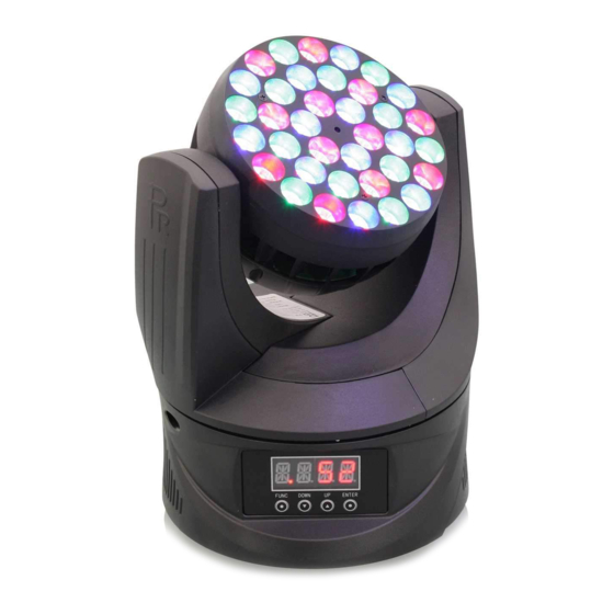
XLED 336 BEAM
PR-8110
This product manual contains important information about the safe installation and use of this
product. Please read and follow these instructions carefully before installing and using the product
and keep this manual in a safe place for future reference.
PR LIGHTING LTD.
http://www.pr-lighting.com
Advertisement
Table of Contents

Summary of Contents for PR Lighting PR-8110
- Page 1 This product manual contains important information about the safe installation and use of this product. Please read and follow these instructions carefully before installing and using the product and keep this manual in a safe place for future reference. PR LIGHTING LTD. http://www.pr-lighting.com...
-
Page 2: Table Of Contents
INDEX SAFETY INFORMATION AND WARNINGS PRODUCT INSTALLATION POWER SUPPLY CONNECTION DMX CONTROL CONNECTION DMX TERMINATOR PRODUCT FUNCTION SETUP DMX START ADDRESS SETUP STAND-ALONE MODE MASTER/SLAVE MODE OPERATION MENU DMX PROTOCOL DISPLAY INFORMATION MAINTENANCE PRODUCT CLEANING TROUBLESHOOTING TECHNICAL DATA COMPONENT ORDER CODES CIRCUIT DIAGRAM Every ex-company fixture is tested completely and packed properly by the manufacturer. -
Page 3: Safety Information And Warnings
SAFETY INFORMATION AND WARNINGS After receiving product, please unpack and check if there are any damages caused by transportation. Do not use the fixture if transportation damages occur and contact the manufacturer or the dealer as soon as possible. The product is only for indoor use, IP20. Use only in dry locations. Keep this device away from rain and moisture, excessive heat, humidity and dust. -
Page 4: Product Installation
PRODUCT INSTALLATION CLAMP SAFETY CORD CONTROL PANEL WARNING: Please run the safety cord through safety hole and make sure that the cord is property secured. Take 1 clamp and 1 the safety cord out from the package and mount 1 clamp on the BOTTOM of fixture with 2 retainers attached to the clamp. -
Page 5: Power Supply Connection
POWER SUPPLY CONNECTIONS Connect the power cord as follows: L (live) =brown E (earth) =yellow/green N (neutral) =blue Please be advised to notice power supply’s voltage and frequency meet what are described on the nameplate of the product. It is recommended that each unit be power connected separately so that they may be individually switched on and off. -
Page 6: Dmx Terminator
DMX TERMINATOR In the Controller mode, at the last fixture in the chain, the DMX output has to be connected with a DMX terminator. This prevents electrical noise from disturbing and corrupting the DMX512 control signals. The DMX terminator is simply a Canon connector with a 120Ω (ohm) resistor connected across pins 2 and 3, which is then plugged into the output socket on the last fixture in the chain. -
Page 7: Stand-Alone Mode
STAND-ALONE MODE Operate the fixture without connecting a controller, enable the master mode in the operation panel, the fixture will run in Stand-Alone mode automatically. MASTER/SLAVE MODE If many fixtures are connected under Master/Slave mode, use XLR-XLR control cable to connect the first fixture’s DMX output port with the second fixture’s DMX input port, then to connect the second fixture’s output port with the third fixture’s input port and so on until all the fixtures are connected, the last thing is to plug the terminator at the last fixture’s output port. -
Page 8: Operation Menu
OPERATION MENU 1st LEVEL 2nd LEVEL 3rd LEVEL 4th LEVEL AddR DMX Address (XXX:1~512) Standard mode DMX mode (Default is:STd) Extended mode dISP Display settings (Default is:ON) digital CRT off if buttons not pressed in 5 minutes Pan Tilt Swap off xyCH Pan Tilt Swap (Default is OFF)... -
Page 9: Dmx Protocol
P*TS 0-255 Pan/Tilt speed Pan/Tilt speed RESE Reset DMX mode PRUN Run preset memory ERUN Run user program CH01 0-255 Strobe CH02 0-255 Red Dimming mENU CH03 0-255 Operation Mode Greening Dimming CH04 0-255 ET XX Blue Dimming User memory from (ET 01 to ET16) CH05 0-255... -
Page 10: Maintenance
192-223 White 224-255 Red & White 000-255 Linear dimming from dark to bright Green 000-255 Linear dimming from dark to bright Blue 000-255 Linear dimming from dark to bright 000-255 Hue Options Saturation 000-255 Saturation from light to dark Brightness 000-255 From Dark to Bright Strobe... -
Page 11: Product Cleaning
PRODUCT CLEANING To ensure the reliability of the fixture it should be kept clean. It is recommended that the fans should be cleaned every 15 days. The lens should also be regularly cleaned to maintain an optimum light output. Do NOT use any type of solvent containing chemical elements. - Page 12 DIMMER: 0-100% linearly adjustable STROBE: Electronic strobe, 0.3~20 F.P.S HEAD MOVEMENT: Pan 540º, Tilt 270º; Pan Tilt Swap and Invert Function ;Auto-position correction & Magnetic sensor positioning. 8° LENS ANGLE: FIELD ANGLE (Without Frost board) : (One-tenth-peak luminance angle) 17° BEAM ANGLE (Without Frost board) : (Half-peak luminance angle) 8°...
- Page 13 223.88 149.99 LIGHT OUTPUT (WITHOUT FROST BOARD): 13/16...
-
Page 14: Component Order Codes
LIGHT OUTPUT (WITH FROST BOARD): COMPONENT ORDER CODES NAME PART NO. QUANTITY REMARK POWER SUPPLY 192010150 1 PCS 90-264V AC/3.0 A LED ( RED COLOR) 150020217 12 PCS 3Wx12 LED ( BLUE COLOR) 150020218 12 PCS 3Wx12 LED (GREEN COLOR) 150020219 12 PCS 3Wx12... -
Page 15: Circuit Diagram
CIRCUIT DIAGRAM 15/16... - Page 16 PR LIGHTING LTD. 1582 Xingye Avenue, Nancun Panyu Guangzhou, 511442 China TEL: +86-20-3995 2888 FAX: +86-20-3995 2330 P/N: 320020115 Version: 20121126 16/16...


Need help?
Do you have a question about the PR-8110 and is the answer not in the manual?
Questions and answers