
Related Manuals for Waters nanoACQUITY UPLC


Summary of Contents for Waters nanoACQUITY UPLC
- Page 1 UPLC System Quick Start Guide 71500097503/Revision D C O R P O R A T I O N Copyright © Waters Corporation 2006. All rights reserved.
- Page 2 Corporation assumes no responsibility for any errors that may appear in this document. This document is believed to be complete and accurate at the time of publication. In no event shall Waters Corporation be liable for incidental or consequential damages in connection with, or arising from, the use of this document.
- Page 3 Please contact us if you have questions, suggestions for improvements, or find errors in this document. Your comments will help us improve the quality, accuracy, and organization of our documentation. You can reach us at tech_comm@waters.com. Waters Corporation 34 Maple Street...
-
Page 4: Operating This Device
Operating this device When operating this device, adhere to standard quality control procedures and the following equipment guidelines. Attention: Changes or modifications to this unit not expressly approved by the party responsible for compliance could void the user’s authority to operate the equipment. - Page 5 Caution: Use caution when working with any polymer tubing under pressure: • Always wear eye protection when near pressurized polymer tubing. • Extinguish all nearby flames. • Do not use tubing that has been severely stressed or kinked. • Do not use nonmetallic tubing with tetrahydrofuran (THF) or concentrated nitric or sulfuric acids.
- Page 6 Attenzione: prestare attenzione durante l’utilizzo dei tubi di polimero pressurizzati: • Indossare sempre occhiali da lavoro protettivi nei pressi di tubi di polimero pressurizzati. • Estinguere ogni fonte di ignizione circostante. • Non utilizzare tubi soggetti che hanno subito sollecitazioni eccessive o son stati incurvati.
- Page 8 Caution: The user shall be made aware that if the equipment is used in a manner not specified by the manufacturer, the protection provided by the equipment may be impaired. Attention: L’utilisateur doit être informé que si le matériel est utilisé d’une façon non spécifiée par le fabricant, la protection assurée par le matériel risque d’être défectueuses.
- Page 9 Caution: To protect against fire hazard, replace fuses with those of the same type and rating. Attention: Remplacez toujours les fusibles par d’autres du même type et de la même puissance afin d’éviter tout risque d’incendie. Vorsicht: Zum Schutz gegen Feuergefahr die Sicherungen nur mit Sicherungen des gleichen Typs und Nennwertes ersetzen.
- Page 10 Caution: To avoid possible electrical shock, disconnect the power cord before servicing the instrument. Attention: Afin d’éviter toute possibilité de commotion électrique, débranchez le cordon d’alimentation de la prise avant d’effectuer la mainte- nance de l’instrument. Vorsicht: Zur Vermeidung von Stromschlägen sollte das Gerät vor der Wartung vom Netz getrennt werden.
-
Page 11: Observing Safety Precautions
Observe all safety precautions while servicing, repairing, installing, and operating the instrument. Failing to do so violates safety standards and intended use of the instrument. Waters Corporation assumes no liability for failure to comply with these precautions. Precautions can be of these two types: •... -
Page 12: Using Waters Equipment
Using Waters equipment In addition to warning symbols, you might encounter the following symbols and labels on packaging, instruments, and/or in documents. Direct current Alternating current Protective conductor terminal Frame or chassis terminal Fuse Electrical power on Electrical power off... -
Page 13: Safety And Electromagnetic Equipment Compatibility
Shielded cables must be used with this unit to ensure compliance with the Class B FCC limits. United States – safety requirements Waters products meet the safety requirements for laboratory instruments set forth by the Occupational Safety and Health Administration (OSHA). All products are evaluated by an OSHA-approved, Nationally Recognized Testing Laboratory (NRTL) to ensure they meet applicable safety standards. -
Page 14: Canada - Spectrum Management
Waters products carry a safety label from an NRTL to show compliance. The particular safety standard with which Waters complies is UL 61010A-1: Electrical equipment for laboratory use; Part 1: General Requirements. Canada – spectrum management This Class B digital apparatus complies with Canadian ICES-003. -
Page 15: Nanoacquity Uplc System Information
UPLC system for analyzing compounds and introducing separated sample components into a mass spectrometer. The Waters nanoACQUITY UPLC system is not intended for use in diagnostic procedures. When you develop methods, follow the “Protocol for the Adoption of Analytical Methods in the Clinical Chemistry Laboratory,”... -
Page 17: Table Of Contents
United States – safety requirements .............. xiii Canada – spectrum management ..............xiv Europe – safety and electromagnetic compatibility........xiv Australia – emissions requirements ..............xiv nanoACQUITY UPLC system information ............ xv Intended use....................... xv Biological hazard....................xv Calibration ......................xv Quality control .................... - Page 18 Mass detectors ....................1-10 Q-Tof Premier™ ..................... 1-10 LCT Premier™ ....................1-11 MassLynx data system ................... 1-11 nanoACQUITY UPLC Console ..............1-11 2 Preparing System Hardware ............... 2-1 Powering-on the system .................. 2-1 Monitoring startup tests ................. 2-2 Monitoring the LEDs of system instruments ..........2-2 Power LED .......................
- Page 19 More than 72 hours (long-term) ..............2-25 3 Configuring System Software ............. 3-1 Configuring MassLynx ..................3-1 Starting the nanoACQUITY UPLC Console from MassLynx ....3-5 Configuring events ................... 3-6 4 Verifying System Operation ..............4-1 Required materials ................... 4-1 Preparing the mobile phases .................
- Page 20 Table of Contents...
-
Page 21: System Overview
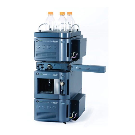
1-11 Instruments and components ® The Waters nanoACQUITY UPLC™ system is designed for capillary-to- nano-scale separations. Its sensitivity, resolution, and reproducibility well suit it for biomarker discovery and proteomics applications, including protein identification and characterization. The system consists of these modules and components: •... - Page 22 The system is optimized for high-resolution separations at precise nanoflow rates. With closed loop control, those rates range between 0.20 and 5.00 µL/min. With open loop control and nanoACQUITY UPLC columns of internal diameters ranging from 75 µm to 1 mm, the nanoflow rates can extend to 100 µL/min.
-
Page 23: Nanoacquity Operating Modes
Waters offers nanoACQUITY UPLC columns packed with 1.7-µm, bridged, ethane-silicon (BEH), hybrid particles as well as conventional reversed phase packing materials, typically 3- to 5-micron particle sizes. Compared with... -
Page 24: Direct Injection
For typical operating conditions, use the following table as a starting point. nanoACQUITY UPLC typical operating conditions: Trap Analytical Analytical Trapping Column Injection Mode Column ID Flow Rate Flow Rate (ID, µm × Volume (µL) (µm) (µL/min) (µL/min) length, mm) Direct 0.20—0.40... -
Page 25: Two-Pump Trapping
Two-pump trapping With two-pump trapping, the sample manager loads the sample into the sample loop. A dedicated trapping pump in the auxiliary solvent manager (pump A) then loads the sample onto the trapping column. With the HTM (heating and trapping module) valve in the waste position, unwanted solutes flush through the trapping column and elute to waste while the column retains the analytes. -
Page 26: Nanoacquity Binary Solvent Manager
nanoACQUITY binary solvent manager The nanoACQUITY binary solvent manager is a high-pressure pump that moves solvent through the system. It provides steady (pulse-free) solvent flow at flow rates ranging from 0.20 to 5.00 µL/min (under closed loop control) or to 100.0 µL/min (under open loop control) at 69,000 kPa (690 bar, 10,000 psi). -
Page 27: Auxiliary Solvent Manager
Auxiliary solvent manager The nanoACQUITY auxiliary solvent manager incorporates two isocratic, high-pressure pumps that move solvent through the system and provide steady (pulse-free) solvent flow. • Pump A is for sample loading. • Pump B is for NanoLockSpray lock-mass addition, two-pump trapping, and 2D online separation. -
Page 28: Sample Consumption Guidelines
Sample consumption guidelines Sample consumption varies depending on your system configuration and injection mode. Sample consumption guidelines Requested Sample Maximum System Injection Mode Sample Size Consumed Injection Configuration (µL) (µL) Volume (µL) Loop: 2 µL Partial loop Needle: 15 µL Partial loop with Not applicable Not applicable Not applicable needle overfill... -
Page 29: Heating And Trapping Module
The heating and trapping module is attached to the sample manager and serves as its top cover. The heating and trapping module’s column tray can accommodate a nano tee and any analytical Waters column up to 300 microns internal diameter and 250 mm length. The column compartment heats to temperatures from 5 °C (9 °F) above ambient to 65 °C (149 °F). -
Page 30: Tuv Optical Detector
® (3.5 µm) or Atlantis dC18 columns (3.0 µm). The nanoACQUITY UPLC trap column is 180 µm I.D. × 2 cm long with • Symmetry C18, 5 µm particles. An ion exchange column of 180 µm I.D. × 2.4 cm length with SCX •... -
Page 31: Lct Premier
LCT Premier™ The Waters LCT Premier is a benchtop mass spectrometer that uses a high resolution, orthogonal acceleration (oa), time-of-flight (ToF) design to enable automated exact mass measurements. The instrument provides information on elemental composition, structural characteristics (through the use of in-source collision-induced dissociation), and specificity for identifying compounds in complex matrices or from a database search. - Page 32 1-12 System Overview...
-
Page 33: Preparing System Hardware
Preparing System Hardware Contents: Topic Page Powering-on the system Monitoring startup tests Monitoring the LEDs of system instruments Preparing the auxiliary solvent manager Preparing the binary solvent manager Preparing the sample manager 2-12 Preparing the detector 2-21 Conditioning the column 2-23 Shutting down the system 2-24... -
Page 34: Monitoring Startup Tests
LED shows steady green. The auxiliary solvent manager’s and binary solvent manager’s flow LEDs and the sample manager’s run LED are unlit. The detector’s lamp LED shows steady green. Power-on the workstation. You can monitor the nanoACQUITY UPLC Console for messages and visual signals. Start MassLynx. -
Page 35: Status Leds
Status LEDs Flow LED (Auxiliary and binary solvent managers) The flow LED, to the right of the power LED on the front panels of the auxiliary and binary solvent managers, indicates the flow status. Run LED (Sample manager) The run LED, to the right of the power LED on the sample manager’s front panel, indicates the run status. -
Page 36: Preparing The Auxiliary Solvent Manager
If the LED is still constant red, contact your Waters service representative. Preparing the auxiliary solvent manager For optimal performance of the nanoACQUITY UPLC system, you must prepare the solvent manager for operation. Preparing the auxiliary solvent manager includes •... -
Page 37: Priming The Seal Wash
Solvent drop-down list of the solvent manager’s instrument method dialog box. • The nanoACQUITY UPLC System should not be run with high pH mobile phases. Alkaline solutions such as ammonium hydroxide (pH 10) can etch glass solvent bottles and the silica capillary tubing, resulting in an elevated chemical background being detected by mass spectrometry. - Page 38 In the nanoACQUITY UPLC Console, select Auxiliary Solvent Manager from the system tree. Click Control > Prime seal wash, and then click Start.
- Page 39 • Running the system after it has been idle for more than four hours To prime the auxiliary solvent manager: In the nanoACQUITY UPLC Console, select Auxiliary Solvent Manager from the system tree. Click Control > Prime A/B Solvents. Prime A/B Solvents dialog box: Select solvent B, and then select B1.
-
Page 40: Preparing The Binary Solvent Manager
Preparing the binary solvent manager For optimal performance of the nanoACQUITY UPLC system, you must prepare the solvent manager for operation. Preparing the solvent manager includes these tasks: • Priming the seal wash • Priming the binary solvent manager Warning: Observe safe laboratory practices when you handle solvents. - Page 41 In the nanoACQUITY UPLC Console, select Binary Solvent Manager from the system tree. Click Control > Prime seal wash, and then click Start to begin the seal-wash priming process.
-
Page 42: Priming The Binary Solvent Manager
Recommendations: • Whenever you change solvents, always purge and autozero the flow control module (see the nanoACQUITY UPLC System Operator’s Guide). • Ensure the solvent reservoirs contain enough solvent for adequate priming and use, and ensure the waste container has sufficient capacity for used solvent. - Page 43 Prime A/B Solvents dialog box: Select solvent A1 or B1. In the Time (min) box, specify the number of minutes from 0.10 through 999.99. The default value is 1.0 minute. Recommendation: 2.0 minutes. Click Start. When finished, repeat as needed for B1 and for all solvents in use. 2-11...
-
Page 44: Preparing The Sample Manager
Caution: The nanoACQUITY UPLC System should not be run with high pH mobile phases. Alkaline solutions such as ammonium hydroxide (pH 10) can etch glass solvent bottles and the silica capillary tubing, resulting in an elevated chemical background being detected by mass spectrometry. - Page 45 Suggested wash solvents: • Strong wash solvent—50 to 100% acetonitrile/water or methanol/acetonitrile (with 0.1% formic acid) • Weak wash solvent—100% water, or 0 to 25% acetonitrile or methanol (with 0.1% formic acid); initial conditions of the gradient or isocratic conditions. High sample concentrations can require other weak wash solvents.
-
Page 46: Priming The Sample Manager
Wash solvent effects: (Continued) Property Effect Sample diluent The weak wash solvent can contact the sample, so match the weak wash solvent and sample matrix as closely as possible. To offset adverse effects on peak shape caused by the matrix’s composition, adjust the weak wash composition when using the module in partial loop mode. -
Page 47: Washing The Sample Manager Needle
To prime the sample manager: In the nanoACQUITY UPLC Console, select Sample Manager from the system tree. Click Control > Prime syringes. Alternative: Right-click in the MassLynx sample manager control panel, and then click Prime syringes. Prime Syringes dialog box: Select Sample syringe and wash syringes. - Page 48 To wash the sample manager needle: In the nanoACQUITY UPLC Console, select Sample Manager from the system tree. Click Control > Wash Needle.
-
Page 49: Characterizing The Needle Seal
Tip: Using both a weak and strong wash solvent increases the wash time and solvent consumption because the system must be fully cleansed of the strong solvent before starting the next injection. In the Weak Wash box, specify the volume for the weak wash solvent. The default value is 200.0 µL. -
Page 50: Characterizing The Needle And Sample Loop Volumes
To characterize the needle seal: In the nanoACQUITY UPLC Console, select Sample Manager from the system tree. Click Maintain > Characterize > Needle seal. In the Characterize Needle Seal dialog box, click Start. The calibrate seal operation begins, and the sample manager status displays “Calibrating seal.”... -
Page 51: Loading Sample Plates In The Sample Manager
The left plate is referred to as position 1, the right one as position 2. The nanoACQUITY UPLC Sample Manager (SM) supports ANSI sample plates and vial holders only. The Sample Manager (SM) does not support vial plates with cap mats or vials without pre-slit septa. - Page 52 Positioning the sample plate: Sample plate A-1 well position Button Plate tray TP02389 Slide the tray into the sample manager until it clicks into place. Close the sample compartment door. A mechanism on the door ensures the plates are positioned correctly when the door closes. Caution: The plates must be positioned correctly to avoid damaging the sample needle.
-
Page 53: Preparing The Detector
Initialization requires approximately 2 minutes, and lamp warm-up requires approximately 3 minutes. When the lamp LED shows constant green, start MassLynx. You can monitor the nanoACQUITY UPLC Console for messages and visual signals. For best results, allow 30 minutes for the baseline to stabilize. Tip: The absorbance value appears in the nanoACQUITY UPLC Console and also in the MassLynx Inlet Editor window. -
Page 54: Preparing The Mass Spectrometer
Recording sample and reference energies After you install the detector or perform maintenance operations, like changing the lamp or flow cell, complete the procedures in this section to verify that the detector optics and electronics work properly. To record sample and reference energies: Ensure that the detector is connected to the workstation. -
Page 55: Conditioning The Column
Conditioning the column Conditioning the column involves running a solvent gradient through it without injecting samples or running the Events table. The run time for conditioning the column should equal the gradient table run time. Tips: • Flush new columns with high organic (up to 85%) for 15 to 20 minutes at your typical analytical flow rate. -
Page 56: Shutting Down The System
Shutting down the system Caution: Buffers left in the system can precipitate, damaging module components. You might want to shut down the system • between analyses • overnight • for a weekend • for 72 hours or more Tip: Set system shutdown parameters in the MassLynx Shutdown Editor. Consult the MassLynx Online Help for more information. -
Page 57: More Than 72 Hours (Long-Term)
The heating and trapping module can operate overnight but should be shut down over the weekend. Warning: To prevent injury, set the power switch to off, and then unplug its power cord from the AC outlet to completely interrupt power to a system module. - Page 58 2-26 Preparing System Hardware...
-
Page 59: Configuring System Software
Configuring System Software Contents: Topic Page Configuring MassLynx Starting the nanoACQUITY UPLC Console from MassLynx Configuring events Configuring MassLynx Requirements: • MassLynx software must be installed. • You must be assigned administrator privileges to configure the Instrument Control Option Pack (ICOP). - Page 60 To select modules in the nanoACQUITY system: In the MassLynx window, click Inlet Method. Inlet Method window: Select Tools > Instrument Configuration. Configuring System Software...
- Page 61 Inlet Configuration window: Click Configure. In the Welcome screen of the Inlet Configuration wizard, click Next. In the Select Pump dialog box, select Waters Acquity, and then click Next. In the Select Auto Sampler dialog box, select Waters Acquity, and then click Next.
- Page 62 You must select ACQUITY TUV Detector even if your system does not include a TUV detector. If you do not do so, the control will be blank when you open the nanoACQUITY UPLC Console. In the Results screen of the Instrument Control Option Pack dialog box, click Finish.
-
Page 63: Starting The Nanoacquity Uplc Console From Masslynx
Starting the nanoACQUITY UPLC Console from MassLynx The nanoACQUITY UPLC Console is a software application that replaces the keypads and small display screens traditionally found on the fronts of system instruments. It provides a convenient way to configure settings, monitor performance, run diagnostic tests, and maintain the system. -
Page 64: Configuring Events
Configuring events Besides making the signal connections, you must configure the events in MassLynx. To configure events: In the MassLynx window, click Inlet Method. Select Tools > Instrument Configuration. Click Events & Triggering, and then click Next. Select the check boxes that correspond to the event in and event out connections you made to the mass spectrometer. -
Page 65: Verifying System Operation
Before you begin this procedure, the system must be set up and configured as described in the nanoACQUITY UPLC System Operator’s Guide. Required materials Make sure these materials are on hand before you begin the verification test: •... -
Page 66: Preparing The Mobile Phases
Requirement: To prevent contamination, always use powder-free nitrile gloves when handling components of the nanoACQUITY system. Caution: Never change directly between immiscible eluents or between buffered solutions and organic eluents. Immiscible eluents form emulsions in the flow path. Combining buffered solutions and organic eluents can result in salt precipitation in the gradient proportioning valves, pump heads, check valves, or other parts of the system. -
Page 67: Preparing The Sample
Submerge the B1 line in the solvent B reservoir bottle with 0.1% formic acid/acetonitrile. Place the solvent B reservoir bottle in the solvent tray. Preparing the sample The verification test uses the MassPREP Peptide Standard to verify that your system is operating correctly. The mixture includes nine peptides with a broad range of polarities and isoelectric points. -
Page 68: Preparing The System
Install the analytical column in the heating and trapping module, and then connect the column outlet to a suitable waste container. In the nanoACQUITY UPLC Console, perform these tasks if you have not already done so: Prime the A1 and B1 solvent lines for 5 minutes. - Page 69 Prime the sample and wash syringes 20 cycles. Characterize the system volume. Tip: Characterizing the system volume is critical to acceptable sample manager performance. If either the trap or analytical column are new, flush them as follows. Duration Flow rate Trap valve %B solvent (minutes)
-
Page 70: Creating The Test Methods
Creating the test methods Follow the steps below to create the methods, setting the parameter values to match those reflected in the accompanying screen representations. This method is designed as a rapid test procedure implementing a 150-µm ID column at high flow rate. Creating the instrument method To create the instrument method: Create an instrument method with these binary solvent manager... - Page 71 Binary solvent manager instrument parameters (Trapping tab): 20.00 1.00 99.0 15.000 Tip: The instrument Comment field is limited to 500 characters. This ensures correct spacing when generating reports. Recommended trapping parameters (with a 5-microliter loop): Flow rate: 15 µL/min • •...
- Page 72 Set these parameters in the sample manager instrument method. Sample manager instrument parameters: Verifying System Operation...
- Page 73 If your system includes a TUV detector, set these parameters in the TUV detector instrument method. Save the instrument method. Create a sample list composed of six 1-µL injections of the peptides mixture and one 1-µL injection of the blank mobile phase. Tip: The typical column back pressure at 0.400 µL/min is approximately 2300 psi.
-
Page 74: Performing The Test
Performing the test When the system is prepared and the test methods are created, you are ready to perform the test. To perform the test: At the MassLynx main page, select Run > Start. Verify the settings for the test, and then click OK. Verify these options, afterward clicking OK for operations, quantify, and LIMS export. - Page 75 Review the gradient performance report. The system verification test result is “passing” when these conditions are realized: • The peaks are symmetrical, integrated, and identified correctly. (Compare the chromatogram on the report to the sample chromatogram, below, to determine this.) •...
- Page 76 4-12 Verifying System Operation...
Need help?
Do you have a question about the nanoACQUITY UPLC and is the answer not in the manual?
Questions and answers