Advertisement
Quick Links
Advertisement

Related Manuals for Keysight N7024A


Summary of Contents for Keysight N7024A
- Page 1 N7020A & N7024A Power Rail Probes USER GUIDE...
- Page 2 FAR and the DFARS and are set forth specifically in writing elsewhere in the EULA. Keysight shall be under no obligation to update, revise or otherwise modify the Software. With respect N7020A and N7024A Power Rail Probes User’s Guide...
- Page 3 Replacing N7023A Probe Browser Tips / 50 Avoiding Costly Repairs / 51 Common Types of Power Integrity Measurements / 53 Calibrating / 55 N7020A / N7024A Probe’s DC Attenuation/Offset Calibration Using N7022A Main Cable / 56 N7020A and N7024A Power Rail Probes User’s Guide...
- Page 4 Contents N7020A / N7024A Probe’s DC Attenuation/Offset Calibration Using N7023A Probe Browser / 57 Performance Plots / 59 N7020A Performance Plots / 60 N7020A Input Impedance Equivalent Model / 64 N7024A Performance Plots / 66 N7024A Input Impedance Plots / 68...
- Page 5 Keysight N7020A and N7024A Power Rail Probes User’s Guide 1 N7020A / N7024A Probes - Overview Introduction Probe Accessories Oscilloscope Compatibility...
- Page 6 These probes are designed for power integrity measurements such as Periodic and Random Disturbances (PARD), static and dynamic load response, and programmable power-rail response. These probes have an output connector with the Keysight AutoProbe 1 interface that allows these probes to connect directly to a compatible Keysight oscilloscope (see page 16).
- Page 7 N7020A / N7024A Probes - Overview • Large active signal range in addition to the offset range While the N7020A and N7024A probes have a number of features in common, the N7024A NOTE probe is an extension to the capabilities and performance of the N7020A probe. When compared to the N7020A probe, the N7024A probe provides enhanced features such as: >...
- Page 8 N7020A / N7024A Probes - Overview Figure 1 Example of Measured Mean Noise at 2 GHz BW: 1.04369 mV Figure 2 Example of Measured Mean Noise at 20 MHz BW: 443.74 mV N7020A and N7024A Power Rail Probes User’s Guide...
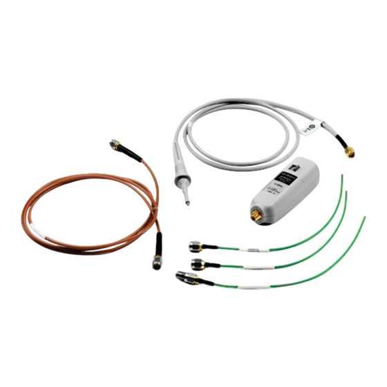
- Page 9 N7020A / N7024A Probes - Overview Probe Accessories Standard Accessories The N7020A and N7024A probes are shipped with the accessories shown in Figure 3 Figure 4 respectively. These standard accessories are described in Table Figure 3 N7020A Probe with Standard Accessories...
- Page 10 Glass Tube containing Cable Spring-loaded and Color Coding Rigid Probe Tips Rings Micro SMD Clip Ground Lead Wrench Ground Rotating Spring N7021A Pigtail Adapter Cables Figure 4 N7024A Probe with Standard Accessories N7020A and N7024A Power Rail Probes User’s Guide...
- Page 11 .035" for probing 0201 and 0402 SMT parts. NOTE: Though this browser is not shipped as a standard accessory with the N7020A probe, you can order it separately for use with the N7020A probe. N7020A and N7024A Power Rail Probes User’s Guide...
- Page 12 “Replacing N7023A Probe Browser Tips" on page 50. Rigid Probe Tips Replaceable probe tips. To know how to replace these tips, refer to “Replacing N7023A Probe Browser Tips" on page 50. N7020A and N7024A Power Rail Probes User’s Guide...
- Page 13 This ensures that you can pick up a probe and immediately know which channel it is connected to without having to track the cable back to the oscilloscope channel input. N7020A and N7024A Power Rail Probes User’s Guide...
- Page 14 Besides the standard accessories that are shipped with the probes, a number of optional accessories are also available that you can order separately. These optional accessories are shown in this picture and briefly described in Table 2 page 15. N7020A and N7024A Power Rail Probes User’s Guide...
- Page 15 0.5 mm pitch (1 pair yellow/green) QFP IC-Clips short down to 0.5 mm 0960-2995 pitch (1 pair yellow/green) Ground Lead 15 cm 0960-2906 N4837A 2-leg Probe Positioner N2786-60001 N2786A Micro SMD Clip 1400-3652 N7020A and N7024A Power Rail Probes User’s Guide...
- Page 16 N7020A / N7024A Probes - Overview Oscilloscope Compatibility The N7020A and N7024A probes are designed for Keysight oscilloscopes with 50Ω N OTE AutoProbe-interface channel inputs. Table 3 Compatible Oscilloscopes for the N7020A and N7024A Probes Compatible Oscilloscopes for the N7020A Probe...
- Page 17 Keysight N7020A and N7024A Power Rail Probes User’s Guide 2 General Information Inspecting the Probe Handling the Probe Cleaning the Probe Returning the Probe for Service Contacting Keysight Technologies...
- Page 18 Sales Office. If the shipping container is damaged, or the cushioning materials show signs of stress, notify the carrier as well as your Keysight Technologies Sales Office. Keep the shipping materials for the carrier’s inspection. The Keysight Technologies office will arrange for repair or replacement at Keysight Technologies’ option without waiting for claim settlement.
- Page 19 WARNING must NOT BE USED if there are any signs of damage. If the N7022A main cable is damaged, it may cause the N7024A probe to not meet its CAUTION warranted bandwidth specification of 6 GHz. It is recommended to verify the cable using the procedure described in “To verify if the N7022A main cable is damaged"...
- Page 20 Gently clean the probe with a soft cloth dampened with a mild soap and water solution. Wipe with clean water to remove the detergent and then dry thoroughly with a clean cloth. Make sure that the probe is completely dry before reconnecting it to an oscilloscope. N7020A and N7024A Power Rail Probes User’s Guide...
- Page 21 Perform the following steps before shipping the probe back to Keysight Technologies for service. Contact your nearest Keysight sales office for information on obtaining an RMA number and return address. Write the following information on a tag and attach it to the malfunctioning equipment.
- Page 22 General Information Contacting Keysight Technologies For technical assistance, contact your local Keysight Call Center. • In the Americas, call 1 (800) 829-4444 • In other regions, visit http://www.keysight.com/find/assist • Before returning an instrument for service, you must first call the Call Center at 1 (800) 829-4444.
- Page 23 Keysight N7020A and N7024A Power Rail Probes User’s Guide 3 Specifications and Characteristics N7020A Probe Specifications and Characteristics N7024A Probe Specifications and Characteristics The tables in this chapter list the specifications and characteristics for the N7020A and N7024A probes. All entries included in this chapter are characteristics unless otherwise NOTE noted.
- Page 24 Non-operating: 25 – 85% room humidity temperatures up to 31 °C, decreasing linearly to 40% at 50 °C Non-operating: 95% room humidity for temperatures up to 40 °C Pollution Degree Pollution Degree 2 N7020A and N7024A Power Rail Probes User’s Guide...
- Page 25 Mechanical Characteristics of N7020A Probe and Browsers Description N7020A Probe N7023A Browser N7032A Browser N7033A Browser Weight 50 g 26 g 10 g 10 g Dimensions Figure 5 on page 27 for dimensions. N7020A and N7024A Power Rail Probes User’s Guide...
- Page 26 Table 7 Safety Specifications of N7020A Power Rail Probe Specification IEC61010-031 For a description of safety markings and symbols on the probe, refer to the chapter “Safety and Regulatory Information" on page 33. N7020A and N7024A Power Rail Probes User’s Guide...
- Page 27 Specifications and Characteristics N7020A Probe, Browsers, and Cables Dimensions Figure 5 N7020A Probe, Browsers, and Accessory Cables Dimensions N7020A and N7024A Power Rail Probes User’s Guide...
- Page 28 Non-operating: 25 – 85% room humidity temperatures up to 31 °C, decreasing linearly to 40% at 50 °C Non-operating: 95% room humidity for temperatures up to 40 °C Pollution Degree Pollution Degree 2 N7020A and N7024A Power Rail Probes User’s Guide...
- Page 29 ± .6V (1.2Vpp) Probe + Oscilloscope 30% increase in the noise of the connected oscilloscope Noise Ω Output Termination scope input Probe Type Single Ended * Warranted specification. All other characteristics are typical. N7020A and N7024A Power Rail Probes User’s Guide...
- Page 30 Specifications and Characteristics Table 10 Mechanical Characteristics of the N7024A Probe and Browsers Description N7024A Probe N7023A Browser N7032A Browser N7033A Browser Weight 155 g 26 g 10 g 10 g Dimensions Figure 6 on page 31 for dimensions. Table 11...
- Page 31 Specifications and Characteristics N7024A Probe, Cables, and Browsers Dimensions Figure 6 N7024A Probe, Browsers, and Accessory Cables Dimensions N7020A and N7024A Power Rail Probes User’s Guide...
- Page 32 Specifications and Characteristics N7020A and N7024A Power Rail Probes User’s Guide...
- Page 33 Keysight N7020A and N7024A Power Rail Probes User’s Guide 4 Safety and Regulatory Information These probes have been designed and tested in accordance with accepted industry standards, and have been supplied in a safe condition. Throughout this manual and specifically in this chapter, there are warnings, cautions, and notes that must be followed by the user to ensure safe operation and to maintain the product in a safe condition.
- Page 34 If you energize the instrument by an auto transformer (for voltage reduction or mains WARNING isolation), the ground pin of the input connector terminal must be connected to the earth terminal of the power source. N7020A and N7024A Power Rail Probes User’s Guide...
- Page 35 (WEEE) is required, as obligated by the EU DIRECTIVE and other National legislation. Please refer to keysight.com/go/takeback to understand your Trade in options with Keysight in addition to product takeback instructions. The product is marked with this symbol when it is necessary for the user to refer to the instructions in the documentation.
- Page 36 Safety and Regulatory Information N7020A and N7024A Power Rail Probes User’s Guide...
- Page 37 Keysight N7020A and N7024A Power Rail Probes User’s Guide 5 Using the Power Rail Probe Requirements for Optimum Probe Performance Low Source Impedance Required Minimize Probe Ground Impedance for the Best Signal Fidelity Connecting to the DUT Replacing N7023A Probe Browser Tips...
- Page 38 N OTE testing to allow the probe to warm up. Connect the N7024A probe to an oscilloscope that has been powered-on for at least 20 minutes to allow the oscilloscope to warm up before any testing. Ensure that the environmental conditions do not exceed the probe’s specified limits in Chapter 3, “Specifications and Characteristics".
- Page 39 Requirements for Optimum Probe Performance Low Source Impedance Required The N7020A and N7024A are designed explicitly for measuring DC power supplies. In order to maintain a flat frequency response across the probe's bandwidth, the DUT must have extremely low source impedance, like that of a power rail.
- Page 40 (N7020A with N7022A Main Cable) Minimize Probe Ground Impedance for the Best Signal Fidelity The N7020A and N7024A probes are single-ended probes that are designed for measuring small signals riding on large DC voltages. By using the oscilloscope’s offset knob to offset the DC voltage, you can analyze a power rail using maximum vertical sensitivity.
- Page 41 You can test this by connecting the probe’s ground and signal contacts to the DUT ground. You should not see any significant signal on the oscilloscope’s screen. N7020A and N7024A Power Rail Probes User’s Guide...
- Page 42 Using the Power Rail Probe Connecting to the DUT You can connect the N7020A / N7024A probe to the DUT in a number of ways using various connection accessories shipped with these probes. The following figure illustrates these connection methods and the correct combination of accessories to be used for the most accurate measurements.
- Page 43 Configuration dialog box. This ensures that you get accurate measurements as per the connection mechanism. For instance, if you are using the N7022A main cable with the N7024A probe, then ensure that the Probe Configuration dialog box has N7022A:N7024A Main Cable as the selected head in the Probe Head section.
- Page 44 Connect the main cable to the N7021A pigtail cable. Use the supplied SMA adapter or Rotating adapter to connect the two cables. Solder the pigtail cable to the DUT. Rotating adapter used to connect the cables N7020A and N7024A Power Rail Probes User’s Guide...
- Page 45 DUT. Using a Power Rail Browser The following browsers are available for use with the N7020A/N7024A probes. Based on your bandwidth requirements, you can choose the browser that you want to use. Refer to Chapter 3, “Specifications and Characteristics"...
- Page 46 N7024A Probe N7024A Probe N7033A Browser Hands-free probing with N7032A / N7033A browser For hands-free stability, you can mount these browsers on the N2787A probe Positioner as displayed in the following figure. N7020A and N7024A Power Rail Probes User’s Guide...
- Page 47 From the set of N7023A browser accessories, choose the accessory that best suits your requirement as per the probing point on the DUT. Connect this accessory to the browser tip as displayed in the figures below. N7020A and N7024A Power Rail Probes User’s Guide...
- Page 48 However, the longer lead means it has a larger inductance in the ground return path which corresponds to a lower performance than using the ground spring. Ground Lead N7020A and N7024A Power Rail Probes User’s Guide...
- Page 49 It is a best practice to twist the leads of the dual lead adapter to reduce coupling of external noise into the probe. Dual Lead Micro SMD Clip Adapter N7020A and N7024A Power Rail Probes User’s Guide...
- Page 50 Figure 10 Proper Tip Removal Technique You should exercise caution when using these sharp browser tips to avoid personal WARNING injury. N7020A and N7024A Power Rail Probes User’s Guide...
- Page 51 1 MΩ of isolation from ground. Purchase acceptable ESD accessories from your local supplier. These techniques for a static-safe work station should not be used when working on WARNING circuitry with a voltage potential greater than 500 volts. N7020A and N7024A Power Rail Probes User’s Guide...
- Page 52 Using the Power Rail Probe Figure 11 ESD Workstation N7020A and N7024A Power Rail Probes User’s Guide...
- Page 53 Using the Power Rail Probe Common Types of Power Integrity Measurements The following are some of the common types of power integrity measurements that you can make using the N7020A / N7024A probe: • Static and dynamic load response. Figure 12 Example of Response to Changing Load •...
- Page 54 • High frequency transients and noise. • PARD (Periodic and Random Disturbances) such as noise, ripple, and switching transients on power rails. Figure 13 Example of PARD on DC Output • Product electrical validation at extended temperatures. N7020A and N7024A Power Rail Probes User’s Guide...
- Page 55 Keysight N7020A and N7024A Power Rail Probes User’s Guide 6 Calibrating N7020A / N7024A Probe’s DC Attenuation/Offset Calibration Using N7022A Main Cable N7020A / N7024A Probe’s DC Attenuation/Offset Calibration Using N7023A Probe Browser Always calibrate the probe before making any critical measurements. A probe calibration removes attenuation errors, offset errors, and timing delays that are introduced by the probe.
- Page 56 N7020A / N7024A Probe’s DC Attenuation/Offset Calibration Using N7022A Main Cable Turn on the oscilloscope and connect the N7020A / N7024A probe with the N7022A main cable attached to one of the oscilloscope’s input channels. Allow the oscilloscope to warm up for 20 minutes.
- Page 57 N7023A Probe Browser Turn on the oscilloscope and connect the N7023A power rail probe browser with the N7020A / N7024A probe attached to one of the oscilloscope’s input channels. Allow the oscilloscope to warm up for 20 minutes. If the oscilloscope needs calibration, perform a user calibration before the probe calibration.
- Page 58 Calibrating N7020A and N7024A Power Rail Probes User’s Guide...
- Page 59 User’s Guide 7 Performance Plots N7020A Performance Plots N7020A Input Impedance Equivalent Model N7024A Performance Plots N7024A Input Impedance Plots This chapter includes plots that show the characteristic performance and an input impedance model of the N7020A and N7024A probes.
- Page 60 The performance characteristic plots in this section are for the N7020A probe with the N7022A main cable attached. Figure 15 Normalized Frequency Response, V , 2.5 GHz BW (N7020A with N7022A Main Cable) N7020A and N7024A Power Rail Probes User’s Guide...
- Page 61 Performance Plots Figure 16 Frequency Response for Different DUT Impedances (N7020A with N7022A Main Cable) N7020A and N7024A Power Rail Probes User’s Guide...
- Page 62 Rise Time, N7020A with N7022A (20/80%): ......192 ps Figure 17 Step Tracking (N7020A with N7022A Main Cable) N7020A and N7024A Power Rail Probes User’s Guide...
- Page 63 Performance Plots Figure 18 Input Impedance Versus Frequency, Measured, Modeled (N7020A with N7022A Main Cable) N7020A and N7024A Power Rail Probes User’s Guide...
- Page 64 T_T1 Vin GND N01605 GND Z0=49.0683 TD=148.305ps R_R4 GND VOUT 50 T_T2 N01605 GND N01608 GND Z0=49.4981 TD=107.256ps T_T7 N01632 GND N01635 GND Z0=50.8744 TD=76.0454ps T_T3 N01608 GND N01611 GND Z0=49.4457 TD=277.663ps R_R1 GND N01635 50k N7020A and N7024A Power Rail Probes User’s Guide...
- Page 65 Performance Plots Figure 19 Input Impedance Equivalent Model N7020A and N7024A Power Rail Probes User’s Guide...
- Page 66 Most high performance active probes for use with Infiniium real-time oscilloscopes utilize DSP correction filters to enhance the measurements accuracy. Probes like the N7024A store their unique s parameters in on-board memory for the scope to readout when needed. Probe heads are simple passive devices and, with careful manufacture, their s-parameters don't vary significantly so they are stored as nominal s-parameters in the oscilloscope.
- Page 67 Performance Plots Figure 20 Typical Corrected Frequency Response for the N7022A Main Cable and N7024A Probe Combination N7020A and N7024A Power Rail Probes User’s Guide...
- Page 68 Performance Plots N7024A Input Impedance Plots This section provides the input impedance plots for various probe configurations available for N7024A based on the different probe and probe head combinations. N7024A Simplified Input Impedance Model Figure 21 shows the model used in the measured and modeled input impedance plots provided for the N7024A probe in this section.
- Page 69 Performance Plots Figure 22 Input Impedances (Z Modeled and Z Measured) for the N7022A Main Cable and N7024A Probe Combination N7020A and N7024A Power Rail Probes User’s Guide...
- Page 70 Performance Plots Input Return Loss Plot for N7022A Main Cable and N7024A Probe Combination Figure 23 Input Return Loss Plot for the N7022A Main Cable and N7024A Probe Combina- tion N7020A and N7024A Power Rail Probes User’s Guide...
- Page 71 In this combination, the value of the inductance L is 1nH. Figure 24 Input Impedances (Z Modeled and Z Measured) for the N7021A Pigtail Cable, N7022A Main Cable, and N7024A Probe Combination N7020A and N7024A Power Rail Probes User’s Guide...
- Page 72 In this combination, the value of the inductance L is 1.85 nH. Figure 25 Input Impedances (Z Modeled and Z Measured) for the N7032A Browser, N7022A Main Cable, and N7024A Probe Combination N7020A and N7024A Power Rail Probes User’s Guide...
- Page 73 In this combination, the value of the inductance L is 1.5 nH. Figure 26 Input Impedances (Z Modeled and Z Measured) for the N7033A Browser, N7022A Main Cable, and N7024A Probe Combination N7020A and N7024A Power Rail Probes User’s Guide...
- Page 74 Performance Plots N7020A and N7024A Power Rail Probes User’s Guide...
- Page 75 Keysight N7020A and N7024A Power Rail Probes User’s Guide 8 Performance Verification DC Input Resistance Performance Verification Bandwidth Performance Verification for N7024A Probe Electrostatic discharge (ESD) can quickly and imperceptibly damage or destroy high CAUTION performance probes, resulting in costly repairs. Always wear a wrist strap when handling...
- Page 76 Performance Verification DC Input Resistance Performance Verification This section provides information to test that the N7020A / N7024A probe meets its warranted DC input resistance, which is 50 kΩ±2%. Allow the N7020A probe to warm up for at least 20 minutes.
- Page 77 Record the result in Table 12 on page 78. To pass this test the result should be between 49 kΩ and 51 kΩ. Performance Test Record Serial #: Date: Tested by: Recommended Next Test Date: N7020A and N7024A Power Rail Probes User’s Guide...
- Page 78 Performance Verification Table 12 Input Impedance Test Results Test Limits Result Pass/Fail Ω 50 k ± 2% N7020A and N7024A Power Rail Probes User’s Guide...
- Page 79 Performance Verification Bandwidth Performance Verification for N7024A Probe This section provides information to test that the N7024A probe meets its warranted bandwidth specification, which is 6 GHz. As the warranted specification is just for the N7024A probe, this performance verification procedure verifies the bandwidth of just the N7024A probe without its N7022A main cable.
- Page 80 Calibration setup with the calibration cable Press [Auto Scale] on the front panel. Choose Setup > Acquisition, then select the Enabled checkbox for Averaging and set the # of averages to 1024. N7020A and N7024A Power Rail Probes User’s Guide...
- Page 81 Set the source for f2 to Function 1 and close the Function dialog box. The oscilloscope is configured as displayed in the figure below. Figure 29 Oscilloscope’s user interface as per the functions defined N7020A and N7024A Power Rail Probes User’s Guide...
- Page 82 1. This will allow you to later compare the saved frequency response of the Cal Out step through the attached calibration coax cable with the frequency response of the N7024A probe (done in steps that follow).
- Page 83 Performance Verification Check the frequency response of the N7024A probe. To do this, perform the following steps. a Disconnect the calibration coax cable and any adapters that you attached to the input channel of the oscilloscope. b Connect the N7024A probe to the input channel and calibration coax cable.
- Page 84 -640mV as displayed in Figure g The f2 trace now has the frequency response with the N7024A probe attached. The already saved and displayed memory 1 trace has the frequency response of the coax cable. For comparison, grab the f2 trace and...
- Page 85 To verify if the N7022A main cable is damaged At times, a damaged N7022A main cable may cause the N7022A+N7024A probe system to not meet its bandwidth specification even when the N7024A has passed the bandwidth verification test described in the previous section.
- Page 86 N7022A main cable. Click OK and close the dialog. The f2 trace now has the frequency response with the N7024A probe attached to the N7022A main cable. The already saved and displayed memory 1 trace has the frequency response of the coax test cable.
- Page 87 GHz or below but the f2 trace is clearly different from the f2 trace displayed in the sample figure below. Figure 34 Frequency response of the N7024A probe with the N7022A main cable N7020A and N7024A Power Rail Probes User’s Guide...
- Page 88 Performance Verification N7020A and N7024A Power Rail Probes User’s Guide...
- Page 89 25, grounding, environmental specifications, 24, inspecting, service, Probe Calibration dialog box, probe tips, grounding probe, repair, humidity, 24, resistance testing, returning for service, input impedance model, input resistance, 25, service, N7020A and N7024A Power Rail Probes User’s Guide...
- Page 90 Index N7020A and N7024A Power Rail Probes User’s Guide...
- Page 91 This information is subject to change without notice. © Keysight Technologies 2014 - 2024 N7020-97005, June 2024 www.keysight.com...
Need help?
Do you have a question about the N7024A and is the answer not in the manual?
Questions and answers