Samson 5857 Mounting And Operating Instructions
Hide thumbs
Also See for 5857:
- Mounting and operating instructions (28 pages) ,
- Mounting and operating instructions (16 pages) ,
- Mounting and operating instructions (12 pages)

Related Manuals for Samson 5857


Summary of Contents for Samson 5857
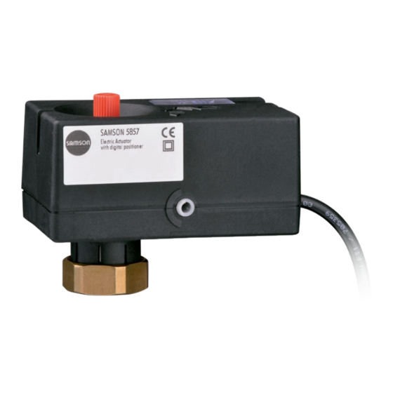
- Page 1 EB 5857 EN Translation of original instructions Type 5857 Electric Actuator Three-step version · Version with digital positioner Firmware version 1.04 Edition September 2018...
- Page 2 Note on these mounting and operating instructions These mounting and operating instructions assist you in mounting and operating the device safely. The instructions are binding for handling SAMSON devices. The images shown in these instructions are for illustration purposes only. The actual product may vary.
-
Page 3: Table Of Contents
Version with digital positioner ..............5-3 Operation ....................6-1 Device overview and operating controls ............6-1 6.1.1 Three-step version ..................6-1 6.1.2 Version with positioner ................6-2 6.1.2.1 Indication with LEDs ..................6-3 6.1.2.2 Direction of action switch ................6-3 6.1.2.3 Initialization key ..................6-4 EB 5857 EN... - Page 4 Error indication by LEDs (version with positioner) ...........9-1 Emergency action ..................9-2 Servicing....................10-1 Decommissioning ..................11-1 Removal ....................12-1 Repairs ....................13-1 13.1 Returning the actuator to SAMSON ............13-1 Disposal ....................14-1 Certificates ....................15-1 Annex A (configuration instructions) ............16-1 16.1 Input signal ....................16-1 16.1.1 Split-range operation ................16-1 16.2...
- Page 5 16.5.5 Dead band (switching range) ..............16-8 16.5.6 Characteristic ...................16-8 16.5.7 Start-up ....................16-10 16.5.8 Functions ('Service' folder) ...............16-10 16.5.8.1 Manual level ...................16-10 16.5.8.2 Functions ....................16-11 Annex B ....................17-1 17.1 Accessories ....................17-1 17.2 After-sales service ..................17-2 17.3 Configuration list and customer-specific data ..........17-3 EB 5857 EN...
-
Page 7: Safety Instructions And Measures
Therefore, operators must ensure that the actuator is only used in operating conditions that meet the specifications used for sizing the actuator at the ordering stage. In case operators intend to use the actuator in other applications or conditions than specified, contact SAMSON. SAMSON does not assume any liability for damage resulting from the failure to use the de- vice for its intended purpose or for damage caused by external forces or any other external factors. Î Refer to the technical data for limits and fields of application as well as possible uses. See the 'Design and principle of operation' section. - Page 8 Responsibilities of operating personnel Operating personnel must read and understand these mounting and operating instructions as well as the specified hazard statements, warning and caution notes. Furthermore, operating personnel must be familiar with the applicable health, safety and accident prevention regula- tions and comply with them. EB 5857 EN...
- Page 9 Î For wiring, maintenance and repair, observe the relevant safety regulations. Referenced documentation The following documents apply in addition to these mounting and operating instructions: − Mounting and operating instructions of the valve on which the electric actuator is mount- ed, e.g. for SAMSON valves: u EB 5866 for Type 3222 Globe Valve u EB 5867 for Type 3222 N Globe Valve u EB 3135-1 for Type 2488 Pressure-independent Control Valve (PICV) u EB 3136 for Type 2488 N Pressure-independent Control Valve (PICV)
-
Page 10: Notes On Possible Severe Personal Injury
Î Before starting any work on the control valve, depressurize all plant sections affect- ed as well as the valve. Î Drain the process medium from all the plant sections affected and from the valve. Î Wear recommended personal protective equipment. See associated valve docu- mentation. EB 5857 EN... -
Page 11: Notes On Possible Personal Injury
Risk of damage to the electric actuator by turning it too far. The actuator stem of the electric actuator can be adjusted manually. Î Move the actuator stem only as far as the bottom or top end position. EB 5857 EN... - Page 12 EB 5857 EN...
-
Page 13: Markings On The Device
Thrust Rated travel Transit time for rated travel Version with digital positioner Supply voltage Power line frequency SAMSON 5857 Power consumption Electric Actuator Input signal with digital positioner 10 Firmware version Var.-ID Firmware-Version: Serial-No. Made in Germany EB 5857 EN... -
Page 14: Firmware Versions
Markings on the device 2.2 Firmware versions Firmware revisions 1) 1.00 Up to 1.04 Internal revisions Only in the version with digital positioner EB 5857 EN... -
Page 15: Design And Principle Of Operation
The motor is switched off by torque-depen- dent limit switches when an end position is reached or in case the motor is overloaded. Travel and direction of action can be read off the travel indicator (5) on the side of the actuator housing. EB 5857 EN... - Page 16 Design and principle of operation Actuator 1.1 Cable Handwheel Actuator stem Coupling nut Travel indicator Plug stem Valve spring Cover (serial interface, direction of action switch, initialization button and LEDs) Only in the version with digital positioner Fig. 3-1: Valve with actuator EB 5857 EN...
-
Page 17: Communication
Support > Downloads > TROVIS-VIEW. Further information on TROVIS-VIEW (e.g. system requirements) is available on our website and in the Data Sheet u T 6661 as well as the Operating Instructions u EB 6661. Î See the 'Start-up and configuration' sec- tion. Serial interface Fig. 3-2: Serial interface EB 5857 EN... -
Page 18: Technical Data
Design and principle of operation 3.2 Technical data Table 3-1: Technical data · Type 5857 Type 5857 Actuator Version Three-step With digital positioner Connection to valve Force-locking Rated travel 6 mm Transit time for rated travel 20 s 30/20 /10 s 1) Stroking speed 0.3 mm/s... -
Page 19: Dimensions
Design and principle of operation 3.3 Dimensions Ø 12 Three-step version Version with digital positioner eL: Actuator stem retracts aL: Actuator stem extends Fig. 3-3: Dimensions in mm EB 5857 EN... - Page 20 EB 5857 EN...
-
Page 21: Shipment And On-Site Transport
4.2 Removing the packaging improper storage. from the actuator Î Observe the storage instructions. Î Avoid long storage times. Î Contact SAMSON in case of different Note storage conditions or longer storage Do not remove the packaging until immedi- times. - Page 22 − Protect the electric actuator against mois- ture and dirt. − Make sure that the ambient air is free of acids or other corrosive media. − Observe the permissible storage tem- perature from –20 to +70 °C. − Do not place any objects on the electric actuator. EB 5857 EN...
-
Page 23: Installation
(see Fig. 5-2). 1. Turn the handwheel (2) counterclockwise to retract the actuator stem. 2. Place the actuator on the valve connec- tion and fasten with the coupling nut (4). 0...90° Tightening torque 20 Nm Fig. 5-1: Mounting orientation EB 5857 EN... -
Page 24: Installing The Control Valve Into The Pipeline
Î Do not install the actuator outdoors. Î During mounting, make sure that the actuator cannot come into contact with any steam. 2 Handwheel 3 Actuator stem 4 Coupling nut Fig. 5-2: Valve with Type 5857 EB 5857 EN... -
Page 25: Electrical Connection
2.5 nF to ensure the proper functioning of the actu- ator. Î Do not use controllers that have interfer- ence suppression capacitor with a higher rating. EB 5857 EN... - Page 26 Actuator cable Connection WH (white) BN (brown) Controller – (al) GN (green) Controller + (el) BN GN Actuator OR Orange Yellow Black Brown GN Green Fig. 5-3: Electrical connection · Three-step Fig. 5-4: Electrical connection · Version with version positioner EB 5857 EN...
-
Page 27: Operation
Operation 6 Operation 6.1 Device overview and operating controls 6.1.1 Three-step version Handwheel Fig. 6-1: Operating controls · Three-step version EB 5857 EN... -
Page 28: Version With Positioner
Red and yellow LEDs Switch position A (front): operating direction increasing/ increasing Switch position B (back): operating direction increasing/ decreasing Direction of action switch with switch positions A and B Initialization key Fig. 6-2: Operating controls · Version with positioner EB 5857 EN... -
Page 29: Indication With Leds
Mixing valve for mixing service For diverting service Flow pipe Flow pipe Return flow pipe Return flow pipe Diverting valve for mixing service For diverting service Flow pipe Flow pipe Return flow pipe Return flow pipe Fig. 6-3: Operating principle of three-way mixing and diverting valves EB 5857 EN... -
Page 30: Initialization Key
6.1.2.3 Initialization key To achieve correct position feedback, the actuator must be initialized. This is also necessary after changing any settings at the actuator. Initialization is started manually by pressing the initialization button (see the 'Start-up and configuration' section). EB 5857 EN... -
Page 31: Start-Up And Configuration
The actuator is not ready to use until the NOTICE initialization is completed. The process is disturbed by the movement of the actuator stem. Î Do not perform the initialization while the process is running. First isolate the plant by closing the shut-off valves. EB 5857 EN... -
Page 32: Configuring The Actuator With Positioner
Time in s 7.3 Configuring the actuator with positioner The actuator is configured with the TROVIS-VIEW software (see Annex A). In this case, the serial interface on the actuator is used to connect the actuator to the computer (see the 'De- sign and principle of operation' section). Î Refer to u EB 6661 for more details on configuration and operation using TROVIS-VIEW. EB 5857 EN... -
Page 33: Operation
The actuator stem's position directly follows the input signal. 8.2.1 LED blinking pattern Explanations to the blinking pattern of the LEDs The state of the corresponding Gray: LED illuminated White: LED not illuminated LED (on/off) is shown over time. Time in s EB 5857 EN... - Page 34 − Stem position is relative Time in s − Protecting against blockage Time in s − Removing blockage Time in s Blinking pattern of the red LED − Restarting device after reset or button pressed Time in s EB 5857 EN...
- Page 35 − Initialization in progress Time in s Note The LED blinking patterns apply when the memory pen is inserted into the actuator (see sec- tion 8.4). The LED blinking patterns for error indication are shown in the 'Malfunctions' section. EB 5857 EN...
-
Page 36: Manual Mode
The positioning of the valve is affected when the handwheel (version with positioner) is oper- ated while the process is running. As a result, zero point and the position feedback do not match the calibrated values. Zero calibration, initialization or a transit time measurement must be performed again. EB 5857 EN... - Page 37 Operation NOTICE Risk of damage to the actuator by turning it too far. Î Move the actuator stem only as far as the bottom or top end position. EB 5857 EN...
-
Page 38: Operation Using Memory Pen
Memory pen actions and errors are indicated at the yellow LED on the actuator. − Memory pen action completed Time in s − Preparing to read data from memory Time in s − Preparing to write data to memory pen Time in s EB 5857 EN... - Page 39 (RJ12 jack) Fig. 8-3: Connecting actuator and memory pen The yellow LED on the actuator indicates that the data logging is being prepared. Data transmission is completed when the yellow LED is illuminated continuously (see the 'Opera- tion' section). EB 5857 EN...
-
Page 40: Copying Function
Î See section 8.4 for the blinking pattern. 1. Plug the memory pen into the serial interface of the actuator (Fig. 8-3). The yellow LED on the actuator indicates that the data logging is being prepared. A change in the blinking pattern of the yellow LED indicates that data are being saved to the memory pen. EB 5857 EN... -
Page 41: Command Mode
In closed-loop operation, the actuator stem can be moved to the top or bottom end position using the command pen regardless of the input signal. Possible settings: − No command − Retract actuator stem − Extend actuator stem EB 5857 EN... -
Page 42: Readings In Trovis-View
Operating hours in h Operating hours at excess temperature in h Temperature inside device in °C Highest temperature inside device in °C Lowest temperature inside device in °C Actuator strokes Motor running time in h Attempts Changes in direction 8-10 EB 5857 EN... -
Page 43: Statistics
Command retract stem Command extend stem Data read Data written Data logged Functions counter Basic settings changed Settings changed Manual level activated Zero calibration started Initialization started Reset triggered Default settings loaded Transit time measurement started EB 5857 EN 8-11... - Page 44 Operation 8-12 EB 5857 EN...
-
Page 45: Malfunctions
Malfunctions 9 Malfunctions Î Troubleshooting (see Table 9-1). Note Contact SAMSON's After-sales Service for malfunctions not listed in the table. Table 9-1: Troubleshooting Error Possible reasons Recommended action Actuator stem does not move. Actuator is blocked. Î Check attachment. Î Remove the blockage. -
Page 46: Emergency Action
− EEPROM error in memory pen Time in s 9.2 Emergency action Plant operators are responsible for emergency action to be taken in the plant. Emergency action in the event of valve failure is described in the associated valve documen- tation. EB 5857 EN... -
Page 47: Servicing
Servicing 10 Servicing Note The electric actuator was checked by SAMSON before it left the factory. − The product warranty becomes void if service or repair work not described in these instructions is performed without prior agreement by SAMSON's After-sales Service. - Page 48 10-2 EB 5857 EN...
-
Page 49: Decommissioning
Valve components and the pipeline may be- come very hot or cold. Risk of burn injuries. Î Allow components and pipelines to cool down or warm up to the ambient tem- perature. Î Wear protective clothing and safety gloves. EB 5857 EN 11-1... - Page 50 11-2 EB 5857 EN...
-
Page 51: Removal
(see associated valve docu- mentation). 1. Disconnect the wires of the connecting lines. 2. Retract the actuator stem using the hand- wheel (see the 'Operation' section). 3. Undo the coupling nut and remove the actuator from the valve connection. EB 5857 EN 12-1... - Page 52 12-2 EB 5857 EN...
-
Page 53: Repairs
Risk of actuator damage due to incorrect service or repair work. Î Do not perform any repair work on your own. Î Contact SAMSON's After-sales Service. 13.1 Returning the actuator to SAMSON Defective actuators can be returned to SAMSON for examination. - Page 54 13-2 EB 5857 EN...
-
Page 55: Disposal
Î Observe local, national and internation- al refuse regulations. Î Do not dispose of components, lubricants and hazardous substances together with your other household waste. On request, we can appoint a service pro- vider to dismantle and recycle the product. EB 5857 EN 14-1... - Page 56 14-2 EB 5857 EN...
-
Page 57: Certificates
Certificates 15 Certificates The following certificates are included on the next pages: − EU declaration of conformity − TR CU certificate The certificates shown were up to date at the time of publishing. The latest certificates can be found on the corresponding product page on our website: u www.samsongroup.com > Products & Applications > Product selector > Actuators > 5857 EB 5857 EN 15-1... - Page 58 Certificates EU declaration of conformity 15-2 EB 5857 EN...
- Page 59 Certificates TR CU certificate EB 5857 EN 15-3...
- Page 60 Certificates 15-4 EB 5857 EN...
-
Page 61: Annex A (Configuration Instructions)
The input signal range can be adapted, e.g. to achieve a plant operation characteristic by connecting two or more actuators in parallel (split-range operation). Example: Two valves regulate the process medium in one common pipeline to achieve a large rangeability. One valve opens with a 0 to 5 V input signal, while the second valve also opens when the input signal increases further (5 to 10 V) and the first valve remains open. The two valves close in the reverse order. EB 5857 EN 16-1... -
Page 62: Position Feedback Signal
If the Input signal failure function is active, the reaction of the actuator upon failure of the in- put signal is determined by the Positioning value upon input signal failure parameter. − 'Positioning value upon input signal failure' = Internal The actuator stem moves to the position specified in the Internal positioning value param- eter upon failure of the input signal. 16-2 EB 5857 EN... -
Page 63: End Position Guiding
When 'End position guiding (stem extends)' = 0 % and 'End position guiding (stem retracts)' = 100 %, the end positioning guiding function is deactivated. Settings\Actuator\Functions Functions Adjustment range End position guiding (stem extends) 1.0 % 0.0 to 49.9 % End position guiding (stem retracts) 97.0 % 50.0 to 100.0 % EB 5857 EN 16-3... -
Page 64: Blockage
When the Blockage removal function is active, the actuator stem extends and retracts 1 mm at the adjusted stroking speed three times in sequence. The action is indicated by the yellow LED (only when the Blockage removal function is active). − Removing blockage Time in s 16-4 EB 5857 EN... -
Page 65: Indicate Blockage
24 hours after it last moved. Movement of the actuator stem caused by the activated blocking protection is indicated by the yellow LED: − Protecting against blockage Time in s Settings\Actuator\Blockage Function Adjustment range Blocking protection No, Yes EB 5857 EN 16-5... -
Page 66: Travel
When, during operation, the actuator stem reaches the travel stop for "stem extends" and, at the same time, the input signal is 0 %, the stem po- sition is recognized as a result. Settings\Actuator\Travel Function Adjustment range Limited travel range 100.0 % 30.0 to 100.0 % In closed-loop operation, the positioner must be operated with absolute travel adjustment (default setting). 16-6 EB 5857 EN... -
Page 67: Idle Time During End Position Guiding
The transit time is calculated from the travel and the stroking speed. The transit time is the time that the actuator stem needs to move through the adjusted travel. Travel in mm Transit time in s = The following applies: Stroking speed in mm/s EB 5857 EN 16-7... -
Page 68: Dead Band (Switching Range)
Settings\Actuator\Travel Function Adjustment range Dead band (switching range) 2.0 % 0.5 to 5.0 % 16.5.6 Characteristic The characteristic expresses the relation between the input signal and the actuator stem posi- tion. Perform the characteristic settings in the Settings folder (Actuator\Characteristic): 16-8 EB 5857 EN... - Page 69 Input signal Y in % − Equal percentage The travel is exponential to the input signal. X in % Input signal Y in % − Reverse equal percentage The travel is reverse exponential to the input signal. X in % Input signal − User-defined A new characteristic based on the characteristic set can be defined over eleven points. EB 5857 EN 16-9...
-
Page 70: Start-Up
− Issue standardized position feedback Î First enter the required position feedback in relation to the span of the position feedback signal (standardized position feedback). − Issue error message − Activate the yellow LED − Activate the red LED 16-10 EB 5857 EN... -
Page 71: Functions ('Service' Folder)
The actuator stem is moved to the position determined by the input signal. Start transit time measurement Measures the time required to move from one end position to the other. EB 5857 EN 16-11... - Page 72 16-12 EB 5857 EN...
-
Page 73: Annex B
− Modular adapter Memory pen-64 Order no. 1400-9753 Connecting cable Order no. 1400-7699 RS232 RJ12 Modular adapter Order no. 1400-7698 USB to RS232 adapter Order no. 8812-2001 RS232 Software TROVIS-VIEW (free of charge) u www.samsongroup.com > Service & Support > Downloads > TROVIS-VIEW EB 5857 EN 17-1... -
Page 74: After-Sales Service
E-mail contact You can reach our after-sales service at u aftersalesservice@samsongroup.com. Addresses of SAMSON AG and its subsid- iaries The addresses of SAMSON, its subsidiaries, representatives and service facilities world- wide can be found on our website (u www.samsongroup.com) or in all... -
Page 75: Configuration List And Customer-Specific Data
Blockage removal Yes/No Indicate blockage Yes/No Blocking protection Yes/No Limited travel range 100.0 % 30.0 to 130.0 % Travel adjustment Absolute Absolute/Relative Velocity Standard Slow/Standard/Fast Dead band (switching range) 2.0 % 0.5 to 5.0 % Linear Equal percentage Characteristic type Linear Reverse equal percent- User-defined EB 5857 EN 17-3... - Page 76 17-4 EB 5857 EN...
- Page 80 EB 5857 EN SAMSON AKTIENGESELLSCHAFT Weismüllerstraße 3 · 60314 Frankfurt am Main, Germany Phone: +49 69 4009-0 · Fax: +49 69 4009-1507 samson@samsongroup.com · www.samsongroup.com...
Need help?
Do you have a question about the 5857 and is the answer not in the manual?
Questions and answers