
Subscribe to Our Youtube Channel
Related Manuals for Samson TROVIS 5578-E


Summary of Contents for Samson TROVIS 5578-E
- Page 1 QUICK GUIDE KA 5578-E EN Translation of original instructions TROVIS 5578-E Heating and District Heating Controller Edition May 2022...
- Page 2 This quick guide assists you in mounting and operating the device safely. The instructions in this quick guide are binding for handling SAMSON devices. Î For the safe and proper use of these instructions, read them carefully and keep them for later reference.
-
Page 3: Table Of Contents
Contents Liability ......................4 Safety instructions ..................4 Electrical connection ..................5 Operating controls ..................8 Operation .....................9 Selecting the operating mode ................9 Schedules ....................10 5.2.1 Setting the time and date ................10 5.2.2 Setting the times-of-use .................12 5.2.3 Setting the party timer (special time-of-use) ............15 5.2.4 Programming public holidays (special times-of-use) ........16 5.2.5... -
Page 4: Liability
We do not assume any liability for the accuracy or completeness of this document. Moreover, we do not guarantee that the buyer can use the product for an intended purpose. SAMSON rejects any liability for claims by the buyer, especially claims for compensation including lost profits or any other financial loss, except the damage was caused intentionally or by gross negligence. -
Page 5: Electrical Connection
Electrical connection 3 Electrical connection Fig. 1: Electrical connection of the TROVIS 5578-E Heating Controller KA 5578-E EN... - Page 6 Return flow sensor Binary input Circulation pump Storage tank sensor Potentiometer (DHW) Water flow sensor TROVIS 5578-E br/sw ws = white gn = green br = brown sw = black Fig. 2: Connection of a water flow sensor KA 5578-E EN...
- Page 7 Electrical connection For RK1: Type 5257-5(x) Room Panel 1) TROVIS 5578-E For RK2: Type 5257-5(x) Room Panel 1) TROVIS 5578-E For RK3: Type 5257-5(x) Room Panel 1) TROVIS 5578-E Type 5244 no longer available Fig. 3: Wiring of a room panel for RK1, RK2 or RK3 Table 1: Permissible wire cross-section for terminals...
-
Page 8: Operating Controls
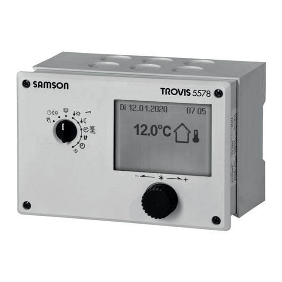
Operating controls 4 Operating controls The heating controller is operated on site using the operating controls on the front. They are located in the front panel of the controller. Rotary pushbutton Turn [q]: Select readings, parameters and function blocks Press [Û]: Confirm adjusted selection or settings Rotary switch The rotary switch is used to set the operating mode and the relevant parameters for each... -
Page 9: Operation
Operation 5 Operation 5.1 Selecting the operating mode The controller can be operated in the following modes: Day mode (rated operation): regardless of the programmed times-of-use and summer mode, the set points relevant to rated operation are used by the controller. Icon: Night mode (reduced operation): regardless of the programmed times-of-use, the set points relevant to reduced operation are used by the controller. -
Page 10: Schedules
Operation ¼ Activate editing mode for the control circuit. The operat- ing mode is shown inverted on the display. q Select the operating mode: Automatic mode Day mode Night mode System deactivated ¼ Confirm the operating mode. The controller is usually in automatic mode. 5.2 Schedules The controller operates according to the schedules in automatic mode. - Page 11 Operation ¼ Activate editing mode for the time. The time reading is inverted. q Change the time. ¼ Confirm the time setting. q Select 'Date' (dd.mm) [q]. ¼ Activate editing mode for the date. The date reading is inverted. q Change date (day.month). ¼...
-
Page 12: Setting The Times-Of-Use
Operation q Select 'Auto summertime'. ¼ Activate the editing mode for automatic summer/stan- dard time switchover. The current setting is shown invert- ed on the display: ON = Summer/standard time switchover active OFF = Summer/standard time switchover not active q Deactivate or activate the automatic summer/standard time switchover. - Page 13 Operation Turn the rotary switch to (times-of-use). The first control circuit is displayed together with its programmed times-of- use. q Program the times-of-use of another control circuit, if re- quired: – Heating circuit HC2 – Heating circuit HC3 – Heating circuit HC11 –...
- Page 14 Operation ¼ Activate editing mode for the period/day. The start time of the first time-of-use period can now be edited (inverted reading). q Change start time. (in steps of 15 minutes) ¼ Confirm the start time. The stop time of the first time-of-use period can now be edited.
-
Page 15: Setting The Party Timer (Special Time-Of-Use)
Operation 5.2.3 Setting the party timer (special time-of-use) Rated operation in the corresponding control circuit (HC1, HC2, HC3 or DHW) is started or continued for the time period set in the party mode. When the party timer has elapsed, the party timer returns to --:--. -
Page 16: Programming Public Holidays (Special Times-Of-Use)
Operation 5.2.4 Programming public holidays (special times-of-use) On public holidays, the times-of-use specified for Sunday apply. A maximum of 20 public holidays may be entered. Parameters Value range Public holidays --:-- 01.01 to 31.12 Turn the rotary switch to (special times-of-use). The party timer for the first control circuit is now selected. -
Page 17: Programming Vacation Periods (Special Times-Of-Use)
Operation After programming all public holidays: q Select 'Back'. ¼ Exit the public holiday setting. Turn the rotary switch back to (operating level). Note Public holidays that are not assigned to a specific date should be deleted by the end of the year so that they are not carried on into the following year. - Page 18 Operation ¼ Start the vacations setting. The first vacations setting is now selected. --.-- - --.--.is displayed if no vacations (de- fault setting) have been programmed. q Select --.-- - --.--, if applicable. q Activate editing mode for vacations. The start date can now be edited (inverted reading). q Set the start date.
- Page 19 Operation Deleting vacation periods: q Select the start date of the period you wish to delete. ¼ Confirm vacation period. q Select --.-- - --.--. ¼ Confirm setting. The vacation period is deleted. After programming all vacation periods: q Select 'Back'. ¼...
-
Page 20: Entering Day And Night Set Points
Operation 5.3 Entering day and night set points The day set points apply during day mode (rated operation) and during times-of-use pro- grammed for automatic mode. The night set points apply during night mode (reduced operation) and outside the times-of- use programmed for automatic mode. -
Page 21: Reset To Default Settings
Operation Switch position Parameters Value range HC1 OT deactivation value 15.0 °C –50.0 to 50.0 °C HC2 OT deactivation value 15.0 °C –50.0 to 50.0 °C HC3 OT deactivation value 15.0 °C –50.0 to 50.0 °C HC11 OT deactivation value 15.0 °C –50.0 to 50.0 °C HC12 OT deactivation value 15.0 °C –50.0 to 50.0 °C HC13 OT deactivation value... -
Page 22: Reading Information
Operation Turn the rotary switch to (settings). q Enter key number 1991. ¼ Confirm key number. The settings are reset to default when the following icon appears on the controller display: 5.5 Reading information Different kinds of information can read off the controller display during operation. The con- troller display usually shows the date, time and an actual temperature when the rotary switch is switched to the 'Operating level' position. - Page 23 Operation q Operating state The following applies for heating circuits HC1, HC2, HC3, HC11, HC12 and HC13: Current op. Current positioning mode value Heating Valve Circulation pump circuit opens (heating) ON/OFF closes The following applies for DHW heating: Current operating mode Pump ON/OFF Storage tank charging pump...
- Page 24 Operation q Times-of-use (depending on the system code number) – Heating circuit HC1 – Heating circuit HC2 – Heating circuit HC3 – Heating circuit HC11 – Heating circuit HC12 – Heating circuit HC13 – DHW heating The day mode times is highlighted in black on the time chart.
- Page 25 Operation q Trend-Viewer The standard graph shows the data measured at the outdoor sensor AF1 and flow sensor VF1 plotted over time. Extended operating level The following details on the controller version (device identification, serial number, software and hardware versions) and meter bus are displayed in the extended operating level.
-
Page 26: Adapting The Trend-Viewer
Operation Note − The additional information is hidden when the key number 1999 is entered again. − The key number 1999 cannot be used to change the controller configuration and parameterization. A separate key number exists for configuration and parameterization (see the 'Start-up' section). - Page 27 Operation Shifting the time line: q Select 'Scroll'. ¼ Activate editing mode for scroll function. q Shift the time line. ¼ Confirm time display. Zooming in/out q Select 'Zoom'. ¼ Open zoom function. q Zoom in or out. ¼ Confirm display. Closing the Trend-Viewer q Select 'Back'.
-
Page 28: Operating The Controller In Manual Mode
Operation 5.6 Operating the controller in manual mode Switch to manual mode to configure all controller outputs. NOTICE System damage caused by frost when manual operating mode is active! The frost protection function is deactivated in the manual operating mode. Î... -
Page 29: Error List
Error list 6 Error list Sensor failure = Sensor failure (see the 'Malfunctions' section in the Mounting and Operating Instructions u EB 5578-E) Disinfection = Disinfection temperature not reached. See 'Thermal disin- fection of DHW storage tank' function in Annex A (con- figuration instructions) of the Mounting and Operating In- structions u EB 5578-E. - Page 32 KA 5578-E EN SAMSON AKTIENGESELLSCHAFT Weismüllerstraße 3 · 60314 Frankfurt am Main, Germany Phone: +49 69 4009-0 · Fax: +49 69 4009-1507 samson@samsongroup.com · www.samsongroup.com...
Need help?
Do you have a question about the TROVIS 5578-E and is the answer not in the manual?
Questions and answers