Samson TROVIS 5724-8 Mounting And Operating Instructions
Without/with fail-safe action electric actuators with process controller for heating and cooling applications
Hide thumbs
Also See for TROVIS 5724-8:
- Mounting and operating instructions (64 pages) ,
- Mounting and operating instructions (64 pages)
Table of Contents
Advertisement
Quick Links
Advertisement
Table of Contents

Subscribe to Our Youtube Channel
Related Manuals for Samson TROVIS 5724-8


Summary of Contents for Samson TROVIS 5724-8
- Page 1 EB 5724-8 EN Translation of original instructions TROVIS 5724-8 (without fail-safe action) TROVIS 5725-8 (with fail-safe action) Electric Actuators with Process Controller For heating and cooling applications Firmware version 2.12 Edition March 2023...
- Page 2 Note on these mounting and operating instructions These mounting and operating instructions assist you in mounting and operating the device safely. The instructions are binding for handling SAMSON devices. The images shown in these instructions are for illustration purposes only. The actual product may vary.
-
Page 3: Table Of Contents
Contents Safety instructions and measures ..............1-1 Notes on possible severe personal injury ............1-5 Notes on possible personal injury ..............1-5 Notes on possible property damage .............1-6 Markings on the device ................2-1 Nameplate ....................2-1 Device code ....................2-2 Firmware versions ..................2-3 Design and principle of operation ...............3-1 Fail-safe action ...................3-1 Communication ..................3-2 Versions .....................3-3... - Page 4 Contents 6.2.1 Readings and their meaning ................6-2 Operating keys ...................6-3 Travel indicator ...................6-4 Interface .....................6-4 6.5.1 Establishing connection with TROVIS-VIEW ...........6-5 Start-up and configuration ................7-1 Initializing the actuator ................7-1 Zero calibration ..................7-1 Communication ..................7-1 7.3.1 Protocol ......................7-3 7.3.2 Modbus parameters ..................7-3 7.4 Configuring the actuator ................7-4 Quick check ....................7-4...
- Page 5 Contents Repairs ....................13-1 13.1 Returning the actuator to SAMSON ............13-1 Disposal ....................14-1 Certificates ....................15-1 Annex A ....................16-1 16.1 Configuration and parameter list ..............16-1 16.2 Excerpt from Modbus list .................16-11 16.3 Default settings and customer-specific data ..........16-16 Annex B ....................17-1 17.1 Accessories ....................17-1 17.2 After-sales service ..................17-2 EB 5724-8 EN...
-
Page 7: Safety Instructions And Measures
(e.g. thrust, travel). Therefore, operators must ensure that the electric actuator with process controller is only used in operating conditions that meet the specifications used for sizing it at the ordering stage. In case operators intend to use the electric actuator with pro- cess controller in applications or conditions other than those specified, contact SAMSON. SAMSON does not assume any liability for damage resulting from the failure to use the de- vice for its intended purpose or for damage caused by external forces or any other external factors. Î Refer to the technical data for limits and fields of application as well as possible uses. See the 'Design and principle of operation' section. - Page 8 − The limit switches switch off the motor in the end positions. − An active blocking protection (A8.3 configuration item = 1, see Annex A) in the electric actuator with process controller prevents the valve from seizing up. − Upon supply voltage failure, the TROVIS 5725-8 Electric Actuator with Process Controller causes the valve to move to a certain fail-safe position. The fail-safe action of SAMSON actuators is specified on the actuator nameplate. Warning against residual hazards The electric actuator with process controller has a direct influence on the valve when it is mounted on the valve.
- Page 9 Safety instructions and measures Responsibilities of operating personnel Operating personnel must read and understand these mounting and operating instructions as well as the referenced documents and observe the specified hazard statements, warnings and caution notes. Furthermore, operating personnel must be familiar with the applicable health, safety and accident prevention regulations and comply with them. Referenced standards, directives and regulations Devices with a CE marking fulfill the requirements of the following Directives: − 2014/30/EU...
- Page 10 The following documents apply in addition to these mounting and operating instructions: − Configuration Manual for TROVIS 5724-8 and TROVIS 5725-8 Electric Actuators with Process Controller u KH 5724-8 − Mounting and operating instructions of the valve on which the electric actuator with pro- cess controller is mounted, e.g. for SAMSON valves: u EB 5861 for Type 3260 Three-way Valve u EB 5863 for Type 3226 Three-way Valve u EB 5866 for Type 3222 Globe Valve u EB 5867 for Type 3222 N Globe Valve...
-
Page 11: Notes On Possible Severe Personal Injury
Safety instructions and measures 1.1 Notes on possible severe personal injury DANGER Risk of fatal injury due to electric shock. Î Before connecting wiring and performing any work on the device, disconnect the supply voltage and protect it against unintentional reconnection. Î Only use power interruption devices that can be protected against unintentional re- connection of the power supply. -
Page 12: Notes On Possible Property Damage
Safety instructions and measures WARNING Risk of personal injury due to incorrect operation, use or installation as a result of information on the electric actuator with process controller being illegible. Over time, markings, labels and nameplates on the electric actuator with process con- troller may become covered with dirt or become illegible in some other way. - Page 13 Safety instructions and measures NOTICE The display does not work due to an interrupted cable connection. The cable connection for the display is located underneath the front housing cover. Î Only open the front housing cover to perform actions described in these instructions. Î...
- Page 14 EB 5724-8 EN...
-
Page 15: Markings On The Device
Markings on the device 2 Markings on the device 2.1 Nameplate The nameplate shown was up to date at the time of publication of this document. The name- plate on the device may differ from the one shown. Type designation Data Matrix code Material number Serial number... -
Page 16: Device Code
Markings on the device 2.2 Device code Electric Actuator with Process Controller TROVIS 572 x - 8 Fail-safe action Without With Rated travel/adaptation 6 mm/force locking 12 mm/force locking 15 mm/form-fit Stem movement Standard EB 5724-8 EN... -
Page 17: Firmware Versions
Markings on the device 2.3 Firmware versions Firmware revisions 2.00 2.01 Communication parameters that cannot be changed are hidden. 2.01 2.10 Automatic protocol detection works with SSP and Modbus. In this case, Modbus is re- stricted to the setting '9600, 8N1'. The 'Communication module' and 'Protocol' communication parameters have been re- placed by the communication parameter with same name (i.e. - Page 18 EB 5724-8 EN...
-
Page 19: Design And Principle Of Operation
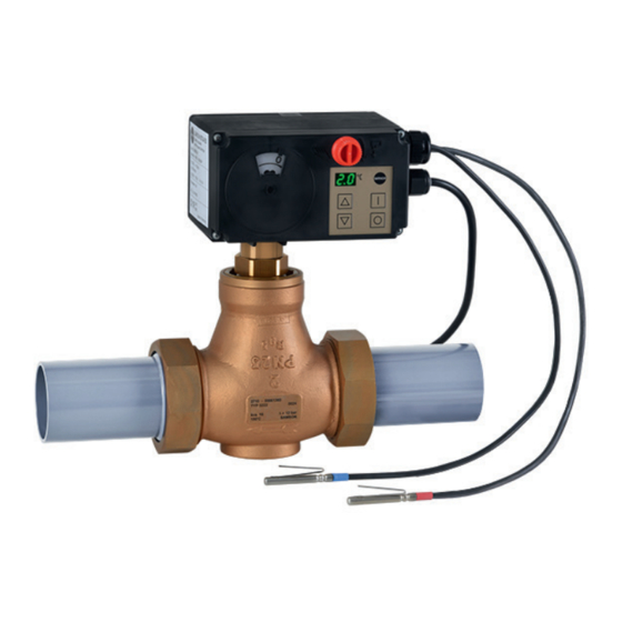
The electric actuators with process controller are mounted onto SAMSON Types 3222, 3213, 3214, 2488, 42-36 E, 3226 and 3260 Valves as well as Series V2001 Valves up to valve size DN 50. Fig. 3-1: TROVIS 5724-8 Electric Actuator with Design Process Controller The actuator contains a reversible synchro- nous motor and a maintenance-free gear. -
Page 20: Communication
TÜV ac- SUPPORT > Downloads > TROVIS-VIEW. cording to DIN EN 14597 in combination Further information on TROVIS-VIEW (e.g. with different SAMSON valves. The register system requirements) is available on our number is available on request. website and in the Data Sheet u T 6661 as well as the Operating Instructions u EB 6661. -
Page 21: Versions
Design and principle of operation 3.3 Versions − Device version [A] with two-wire con- necting cable (voltage supply) and two The electric actuator with process controller Pt1000 sensors is available in four versions [A], [B], [C] and − Device version [B] with three-wire con- [D]. These versions are tailored to the necting cable (voltage supply and switch- ready-configured applications. In many cas- ing output) and two Pt1000 sensors... -
Page 22: Additional Equipment
Design and principle of operation Versions RS-485 interface T1 (AI1, red marking) (R3 port) Pt 1000 • • T2 (AI2, blue marking) Pt 1000 T1 (AI1, red marking) Pt 1000 T2 (AI2, blue marking) Pt 1000 • • Four-wire control line Two-wire connecting cable •... -
Page 23: Technical Data
Design and principle of operation 3.5 Technical data Electric actuator with process 5724- 5725- 5724- 5725- 5724- 5725- TROVIS controller Fail-safe action Without With Without With Without With Actuator stem – – – tends tends tends Connection to valve Force-locking Form-fit Rated travel 6 mm... - Page 24 Design and principle of operation Device version • Two-wire connecting cable with open end for connection to voltage supply (5 m) • 2x Pt1000 sensors (3 m red and 2 m blue) Device version • Three-wire connecting cable with open end for connection to voltage supply and switching output (2.5 m) • 2x Pt1000 sensors (3 m red and 2 m blue) Device version • Two-wire connecting cable with open end for connection to voltage supply (5 m) • 2x Pt1000 sensors (3 m red and 2 m blue) • Four-wire control line for two additional inputs (3 m) Device version • Three-wire connecting cable with open end for connection to voltage supply and switching output (2.5 m) •...
-
Page 25: Dimensions
Design and principle of operation 3.6 Dimensions TROVIS 5724-810/-820 and TROVIS 5725-810/820 TROVIS 5724-830 and TROVIS 5725-830 Ø 15,8 Ø 10 Fig. 3-3: Dimensions in mm EB 5724-8 EN... - Page 26 EB 5724-8 EN...
-
Page 27: Shipment And On-Site Transport
1. Remove the packaging from the electric Î Observe the storage instructions. actuator. Î Avoid long storage times. Î Contact SAMSON in case of different 2. Check scope of delivery (see Fig. 4-1). storage conditions or longer storage 3. Dispose of the packaging in accordance times. - Page 28 Shipment and on-site transport Note We recommend to regularly check the elec- tric actuator with process controller and the prevailing storage conditions during long storage periods. Storage instructions − Protect the electric actuator against exter- nal influences (e.g. impact). − Protect the electric actuator against mois- ture and dirt. − Make sure that the ambient air is free of acids or other corrosive media.
-
Page 29: Installation
Installation 5 Installation NOTICE Risk of actuator damage due to adverse 5.1 Installation conditions weather conditions. Î Do not use the electric actuator with pro- Work position cess controller outdoors. If not described otherwise in the valve docu- mentation, the work position for the control 5.2 Preparation for installation valve is the front view looking onto the oper- ating controls. -
Page 30: Aligning The Travel Indication Scale
Installation 5.3 Aligning the travel indica- NOTICE tion scale The display does not work due to an inter- rupted cable connection. The travel indication scale has two opposed Î Only open the front housing cover to scales. Which scale is to be used depends perform actions described in these in- on the valve version. -
Page 31: Trovis 5724-8 (Force-Locking Attachment)
Installation 5.4.1 TROVIS 5724-8 (force- NOTICE locking attachment) Risk of damage to the actuator by moving the actuator stem too far. Î See Fig. 5-3. Î Only turn the handwheel far enough to 1. Turn the handwheel (3) counterclockwise move the actuator to the top end position to retract the actuator stem. -
Page 32: Trovis 5724-8 (Form-Fit Attachment)
Installation 5.4.2 TROVIS 5724-8 (form-fit Retracting the actuator stem mechanically attachment) 1. Carefully open the front housing cover and place a 4 mm Allen key on the red Î See Fig. 5-3. actuating shaft. 2. Retract the actuator stem: turn Allen key NOTICE counterclockwise and only as far as the Crush hazard arising from moving parts top end position which is at the point (actuator and plug stem). -
Page 33: Installing The Control Valve Into The Pipeline
Installation 5.5 Installing the control valve into the pipeline All ready-configured applications are de- scribed in the Configuration Manual u KH 5724-8. Refer to the plant schemes to NOTICE find out where the sensors are preferably to Degree of protection not achieved due to be mounted for an application. - Page 34 Installation Î Connect the connecting cable to the volt- DANGER age supply (see Fig. 5-5). Risk of fatal injury due to electric shock at switching output L' in device versions B and Note D after connecting the supply voltage. Upon delivery, the sensors are already con- The switching output L' may be live.
- Page 35 Installation Version without switching output Version with switching output DANGER Live wires Î Do not touch wire ends. Control line With Pt1000 and voltage input With two binary inputs Pt 1000 0(2)...10 V Blue Note Brown Terminals are not included in the OG Orange Black scope of delivery.
-
Page 36: Establishing Connection With The Control Station
Installation 5.7.1 Establishing connection with the control station Î Connect the bus connection line for communication over Modbus RTU protocol. White A (incoming) Brown B (incoming) Green A' (outgoing) Yellow B' (outgoing) Black Shielding Fig. 5-6: Bus connection line with three-pin round connector Note Fit the first and last bus participant of the RS-485 bus with an external bus termination. -
Page 37: Operation
Operation 6 Operation 6.1 Device overview and operating controls TROVIS 5724-8: Travel indicator handwheel Display Operating keys RS-485 interface (R3 port) Fig. 6-1: Operating elements on the actuator EB 5724-8 EN... -
Page 38: Display
Operation 6.2 Display Î Error messages (see the 'Malfunctions' section). The actual value (process variable) before Information indicated by the decimal point the comparator for controller [1] or [2] is on the bottom right-hand corner of the dis- shown on the display during closed-loop op- play eration. -
Page 39: Operating Keys
Operation 6.3 Operating keys − Program (program controller) stopped. In closed-loop operation, the operating keys have the function listed in Table 6-1. Time − Program (program controller) finished. Time Table 6-1: Function of the operating keys Function Briefly pressing the key Depending on how A2.1 configuration item is set, a set point, which can be adjust- ed, is displayed (see Annex A). Briefly pressing the key Depending on how A2.2 configuration item is set, a different value is displayed (see Annex A). -
Page 40: Travel Indicator
Operation Function Briefly pressing the key The function depends on how A1.1 configuration item is set (see Annex A). Key held pressed for three seconds Reading H A Open manual level. Key held pressed for six seconds Reading I n Start initialization (see the 'Start-up and configuration' section). Key held pressed for nine seconds Reading C P Set communication parameters (see the 'Installation' section). Key held pressed for twelve seconds Reading U P Start firmware update. -
Page 41: Establishing Connection With Trovis-View
Operation 6.5.1 Establishing connection with TROVIS-VIEW Communication is established between the electric actuator and a computer using an USB-to RS-485 adapter R3. Fig. 6-2: Connecting cable USB-to-RS-485 R3 EB 5724-8 EN... - Page 42 EB 5724-8 EN...
-
Page 43: Start-Up And Configuration
Start-up and configuration 7 Start-up and configuration After initialization is completed, the actuator returns to closed-loop operation. The electric actuator with process controller is started at the operator keys, while it is Note configured with the TROVIS-VIEW software. We recommend reinitializing the actuator if the mounting situation changes. - Page 44 Start-up and configuration We recommend the setting P r = A P. With this setting the electric actuator with process controller automatically detects the required protocol (see section 7.3.1). Table 7-1: Communication parameters C P menu Designation Setting U n Communication unit o F Bluetooth module not active b L...
-
Page 45: Protocol
Start-up and configuration 7.3.1 Protocol detect data transmission errors. The parity bit is added to the end of the string of data The RS-485 data transfer is performed auto- bits and the total value is made up from the matically using an SSP or Modbus RTU pro- data and parity bit. -
Page 46: Configuring The Actuator
Start-up and configuration 7.4 Configuring the actuator Configuration of the electric actuator Î Define Modbus parameters: Î See u KH 5724-8. − Over on-site operation or Ready-configured systems are available to − Using the TROVIS-VIEW software facilitate configuration. As a result, the user Î Perform configuration as required in only needs to change very few settings to TROVIS-VIEW. adapt the device to the application. -
Page 47: Operation
Operation 8 Operation 8.1 Adjusting the set point The valve with electric actuator is ready for Necessary configuration (see Annex A) use when mounting and start-up have been − A2.1 = 1 to change the set point at completed. controller [1] C1.SP − A2.1 = 2 to change the set point at WARNING controller [2] C2.SP Form-fit version: crush hazard arising from moving parts (actuator and plug stem). -
Page 48: Starting/End Closed-Loop Operation
Operation 8.2 Starting/end closed-loop 8.3 Increasing/decreasing the operation set point Necessary configuration (see Annex A) Necessary configuration (see Annex A) − A1.1 = 1 − A1.1 = 2 and A1.5 = 0 or − A1.1 = 2 and A1.5 = 1 or Start closed-loop operation − A1.1 = 2 and A1.5 = 2 or Start closed-loop operation. − A1.1 = 2 and A1.5 = 3 or Readings: − A1.1 = 2 and A1.5 = 4 'on' during start-up time. Afterwards, the value resulting from the A3.1 con- Note figuration item. -
Page 49: Selecting The External/Internal Set Point
Operation 8.4 Selecting the external/in- Necessary configuration (see Annex A) ternal set point − A1.1 = 4 and A1.5 = 0 or − A1.1 = 4 and A1.5 = 1 or Necessary configuration (see Annex A) − A1.1 = 4 and A1.5 = 2 or − A1.1 = 4 and A1.5 = 3 or − A1.1 = 3 and A1.5 = 0 or − A1.1 = 4 and A1.5 = 4 − A1.1 = 3 and A1.5 = 1 or − A1.1 = 3 and A1.5 = 2 or Start and stop program controller − A1.1 = 3 and A1.5 = 3 or Start and stop program controller. − A1.1 = 3 and A1.5 = 4 Restarting the stopped program con- troller causes the program to continue... -
Page 50: Manual Override
Operation 8.6 Manual override NOTICE The display does not work due to an inter- 8.6.1 Manually changing the rupted cable connection. stem position Î Only open the front housing cover to perform actions described in these in- A manual adjustment of the stem position structions. -
Page 51: Changing Manual/Automatic Mode And Setting Manual Positioning Value
Operation 8.7 Changing manual/auto- The actual temperature value appears on the display. matic mode and setting manual positioning value 8.7.2 Changing to manual mode over Modbus 8.7.1 Changing over to manual mode on the de- Manual/automatic switchover vice Coil CL 3 is used for manual/automatic swi- tchover. Î... - Page 52 Operation level is active, the internal manual level (CL 2 = 1) can be activated at the device to override it. In this case, the manual positioning value (HR 21) set at the device becomes effective. After exiting the internal manual level by pressing the key, the manual positioning value of the external manual level (HR 25) becomes effective again. EB 5724-8 EN...
-
Page 53: Malfunctions
Malfunctions 9 Malfunctions 9.1 Troubleshooting Î Troubleshooting (see Table 9-1). Note Contact SAMSON's After-sales Service for malfunctions not listed in the table. Table 9-1: Troubleshooting Malfunction Possible reasons Recommended action Actuator or plug stem does not The actuator stem is blocked. -
Page 54: Error Messages
Malfunctions 9.2 Error messages 9.2.1 Error messages on the display The corresponding reading blinks on the display in the event of a malfunction. Table 9-2: Error messages on the display Reading Error Priority Signal failure AI1 Signal failure AI2 Signal failure AI3 Limit contact error No basic setting No configuration... -
Page 55: Modbus Error
Malfunctions 9.2.2 Modbus error Table 9-3: Modbus error responses/excerpt from Modbus list Error code Error Cause Illegal function The function code is not supported. Illegal data address A register address is invalid or write-protected Illegal data value A value contained in the data is not allowed or not plausible. -
Page 56: Emergency Action
Malfunctions Designation COILS (1-bit) Access Status 0 Status 1 EE-Error manufacturing parameters state EE-Error transit time cause EE-Error status messages state EE-Error status messages cause EE-Error statistics state EE-Error statistics cause 9.3 Emergency action The valve, on which the electric actuator with process controller with fail-safe action is mount- ed, is moved to its fail-safe position upon failure of the supply voltage (see the 'Design and principle of operation' section). -
Page 57: Servicing
Note The electric actuator with process controller was checked by SAMSON before it left the factory. − The product warranty becomes void if service or repair work not described in these instructions is performed without prior agreement by SAMSON's After-sales Service. - Page 58 10-2 EB 5724-8 EN...
-
Page 59: Decommissioning
Decommissioning 11 Decommissioning To decommission the electric actuator for maintenance work or disassembly, proceed The work described in this section is only to as follows: be performed by personnel appropriately 1. Close the shut-off valves upstream and qualified to carry out such tasks. downstream of the control valve to stop the process medium from flowing DANGER through the valve. - Page 60 11-2 EB 5724-8 EN...
-
Page 61: Removal
Removal 12 Removal 2. Undo the coupling nut and remove the electric actuator from the valve connec- The work described in this section is only to tion. be performed by personnel appropriately Form-fit attachment qualified to carry out such tasks. Î See Fig. 12-1. DANGER 1. Retract the actuator stem using the hand- Risk of fatal injury due to electric shock. - Page 62 3. Undo the coupling nut (2) and remove Î Hold the actuating shaft in place after re- the electric actuator from the valve con- tracting the actuator stem to prevent it nection. from extending again. 4. Undo the nut (6) and remove the rod- Form-fit attachment type yoke (4) together with the electric Î...
-
Page 63: Repairs
NOTICE Risk of actuator damage due to incorrect service or repair work. Î Do not perform any repair work on your own. Î Contact SAMSON's After-sales Service. 13.1 Returning the actuator to SAMSON Defective actuators can be returned to SAMSON for examination. - Page 64 13-2 EB 5724-8 EN...
-
Page 65: Disposal
Disposal 14 Disposal SAMSON is a producer registered at the following European institution u https://www.ewrn.org/ national-registers/national- registers. WEEE reg. no.: DE 62194439/FR 025665 Î Observe local, national and internation- al refuse regulations. Î Do not dispose of components, lubricants and hazardous substances together with your other household waste. - Page 66 14-2 EB 5724-8 EN...
-
Page 67: Certificates
Certificates 15 Certificates The following certificates are included on the next pages: − EU declarations of conformity − TR CU certificate − Declaration of incorporation The certificates shown were up to date at the time of publishing. The latest certificates can be found on our website: u www.samsongroup.com > Products & Applications > Product selector > Actuators > 5724-8 u www.samsongroup.com > Products & Applications > Product selector > Actuators > 5725-8 EB 5724-8 EN 15-1... - Page 68 LVD 2014/35/EU EN 60730-1:2016, EN 61010-1:2010 RoHS 2011/65/EU EN 50581:2012 Hersteller / Manufacturer / Fabricant: SAMSON AKTIENGESELLSCHAFT Weismüllerstraße 3 D-60314 Frankfurt am Main Deutschland/Germany/Allemagne Frankfurt / Francfort, 2017-07-29 Im Namen des Herstellers/ On behalf of the Manufacturer/ Au nom du fabricant.
- Page 69 LVD 2014/35/EU EN 60730-1:2016, EN 61010-1:2010 RoHS 2011/65/EU EN 50581:2012 Hersteller / Manufacturer / Fabricant: SAMSON AKTIENGESELLSCHAFT Weismüllerstraße 3 D-60314 Frankfurt am Main Deutschland/Germany/Allemagne Frankfurt / Francfort, 2017-07-29 Im Namen des Herstellers/ On behalf of the Manufacturer/ Au nom du fabricant.
- Page 70 Certificates TR CU certificate 15-4 EB 5724-8 EN...
- Page 71 Certificates EB 5724-8 EN 15-5...
- Page 72 Frankfurt am Main, 10 February 2022 Stephan Giesen Sebastian Krause Director Director Product Management Strategic R&D, Valves and Actuators Revision no. 01 Classification: Public · SAMSON AKTIENGESELLSCHAFT · Weismüllerstraße 3 · 60314 Frankfurt am Main, Germany Page 1 of 1 15-6 EB 5724-8 EN...
-
Page 73: Annex A
Annex A 16 Annex A 16.1 Configuration and parameter list Note The default setting depends on the selected system code number. All default settings are listed in section 16.3. CO/PA Function/ Setting/ designation adjustment range I … Inputs and outputs Universal input I1/Universal input I2/Universal input I3 I1/I2/I3 Function 0: None... - Page 74 Annex A CO/PA Function/ Setting/ designation adjustment range Universal input I4 Function 0: None 1: DI4 not inverted 2: DI4 inverted 4: AI4 (0 to 10 V) AI4.I1 Input signal, point 1 0.0 to 99.9 % AI4.COR Offset AI4 –9.9 to +9.9 % 1) AI4.O1 Output signal, point 1 –50 to +150 °C AI4.I2 Input signal, point 2 0.1 to 100.0 %...
- Page 75 Annex A CO/PA Function/ Setting/ designation adjustment range M ... Control Application 0: User-defined System code number 1: Heating · Fixed set point control with one sensor · Internal set point decrease 2: Cooling · Fixed set point control with one sensor · Start/stop control sequence with [I]/[0] keys or with 10: Heating · Fixed set point control · Temperature mean value calculation using two sensors · Internal set point decrease 20: Cooling · Fixed set point control · Differential temperature between two sensors · Start/stop control sequence 21: Cooling · Fixed set point control · Temperature mean value calculation using two sensors · Start/stop control sequence 30: Heating · Follow-up control · Return flow temperature limitation · Internal set point decrease 35: Heating · Follow-up control · Outdoor temperature controlled, return flow temperature limitation · External...
- Page 76 Annex A CO/PA Function/ Setting/ designation adjustment range 58: Heating · Override control with minimum selection · Position transmitter with return flow temperature limitation · Set point/set point with [I]/[O] keys or DI3, off with DI1 60: Cooling · Override control with minimum selection · Differential temperature with two sensors, return flow temperature limitation · Start/stop control sequence 65: Cooling · Override control with minimum selection · Differential temperature with two sensors, return flow temperature limitation · Start/stop control sequence 66: Cooling · Override control for district cooling · Maximum selection of the set point control · Start/stop control sequence 70: Heating · Cascade control with two sensors · Internal set point switchover 75: Cooling · Cascade control with three sensors · Start/ stop control sequence with [I]/[0] keys or with DI4, off with LIM2...
- Page 77 Annex A CO/PA Function/ Setting/ designation adjustment range Control function Control mode Fixed set point/follow-up Override (MIN selection) Override (MAX selection) Controller [1] active when LIM1 = off/Controller [2] active when LIM1 = on Controller [1] active when LIM2 = off/Controller [2] active when LIM2 = on Controller [1] active when DI1 = off/Controller [2] active when DI1 = on Controller [1] active when DI2 = off/Controller [2] active when DI2 = on Controller [1] active when DI3 = off/Controller [2] active when DI3 = on Controller [1] active when DI4 = off/Controller [2] active when DI4 = on Cascade Direction of action >> (increasing/increasing) <> (increasing/decreasing) Internal limit LIM1/Internal limit LIM2 LIM1.S/ Source Measured value AI1 LIM2.S Measured value AI1 after function generation...
- Page 78 Annex A CO/PA Function/ Setting/ designation adjustment range LIM1.F/ Function None LIM2.F Source (signal) ≤ LIM1 Source (signal) ≤ LIM2 Source (signal) ≥ LIM1 Source (signal) ≥ LIM2 LIM1.P/ Switching point –50 to +150 °C LIM2.P LIM1.H/ Hysteresis 0.5 to 10.0 °C LIM2.H Program controller A0.1 Behavior when program 1: Control active, last set point is retained has elapsed 2: Control active, program is repeated cyclically 3: Control inactive, actuator positioning value is 0 % 4: Control inactive, actuator positioning value is 100 % C1 .../C2 ...
- Page 79 Annex A CO/PA Function/ Setting/ designation adjustment range Set point adjustment C1.2/C2.2 Source 0: Set point = C1.SP + C1.e * AI1 + C1.f * AI2 + C1.g * AI3 + C1.h * A different rule applies to 1: Set point = AI1 after function generation controller [2] for C2.2 = 7: 2: Set point = AI2 after function generation Set point = C1.SP + 3: Set point = AI3 after function generation...
- Page 80 Annex A CO/PA Function/ Setting/ designation adjustment range PID controller C1.KP/ Proportional-action coeffi- 0.1 to 999.9 C2.KP cient C1.TN/ Reset time 0 to 999 s C2.TN C1.TV/ Derivative-action time 0 to 999 s C2.TV C1.Y0/ Operating point 0.0 to 100.0 % C2.Y0 Manipulated variable C1.4/C2.4 Function Controller positioning value...
- Page 81 Annex A CO/PA Function/ Setting/ designation adjustment range Actuator A8.1 Zero calibration Extend actuator stem Retract actuator stem A8.2 Restart conditions Start with last operating state Start with operating function [O] Start with operating function [I] A8.3 Blocking protection Characteristic 0: Linear Characteristic type 1: Equal percentage 2: Reverse equal percentage 3: User-defined...
- Page 82 Annex A CO/PA Function/ Setting/ designation adjustment range A1.T.ON Start-up time after start 0 to 999 s A1.YP.ON Positioning value during 0.0 to 100.0 % start-up function A1.T.OFF Lag time after stop 0 to 999 s A1.YP.OFF Positioning value after lag 0.0 to 100.0 % time [Up]/[Down] settings A2.1 [Up] key function...
-
Page 83: Excerpt From Modbus List
Annex A 16.2 Excerpt from Modbus list The firmware version 2.1x of TROVIS 5724-8 and TROVIS 5725-8 Electric Actuators with Process Controller have an integrated RS-485 interface to use the Modbus RTU protocol, which is a master/slave protocol (in which the control station acts as the master and the elec- tric actuator as the slave). The following Modbus functions are supported: Code Modbus function Application Read Coils Read state of several digital outputs in bit format Read Holding Registers Read several parameters Write Single Coil Write a single digital output in bit format Write Single Register... - Page 84 Annex A Transmission range Indicating range Designation Access Start Start Device ID data Device type 5724 5725 5724 5725 Implementation Revision (e.g. rev. 2.00) 9999 1.00 99.99 Serial number, part 1 (four high-order digits) 9999 9999 Serial number, part 2 (four low-order digits) 9999 9999 Firmware version...
- Page 85 Annex A Transmission range Indicating range Designation Access Start Start Manual level Manual positioning value (external) 1000 100.0 Set point deviation of the external manual 1000 100.0 level Operating values (operating function) Operating function status Operating function cause Program controller set point –500 +1500 –50.0 +150.0 Program controller time elapsed 10080 10080 Reserved (time elapsed for start function)
- Page 86 Annex A Transmission range Indicating range Designation Access Start Start Operating values and settings of controller [2] Actual value before comparator of controller –500 +1500 –50.0 +150.0 [2] (PV[2]) Set point before comparator of controller [2] –500 +1500 –50.0 +150.0 (SP[2]) Set point deviation of controller [2] (SP[2] –...
- Page 87 Annex A Designation COILS (1-bit) Access Status 0 Status 1 Limits State of internal limit 1 State of internal limit 2 Limit switches State of limit switch "stem retracted" State of limit switch "stem extended" Switching output Logical state of switching output Switching contact of switching output Enable manual level for switching output Logical state (manual level for switching out- put)
-
Page 88: Default Settings And Customer-Specific Data
Annex A 16.3 Default settings and customer-specific data If a system code number ≠0 is switched to system code number 0, the data of previously se- lected system code number are adopted. Any parameters not used in this configured system are written with the default setting. The electric actuator with process controller is delivered with the system code number 10 (fixed set point control, heating with mean value calculation of two sensors and set point de- crease) set by default. Note The values in dark gray fields in the following tables cannot be changed. Settings for heating Adjusted value System code... - Page 89 Annex A Adjusted value System code number (WE) AI3.I2 °C AI3.O2 °C 1(2) 1(2) 1(2) AI4.I1 20.0 AI4.O1 °C AI4.I2 99.0 100.0 AI4.O2 °C M4.T Control LIM1.S LIM1.F LIM1.P °C LIM1.H °C LIM2.S LIM2.F LIM2.P °C LIM2.H °C 10.0 EB 5724-8 EN 16-17...
- Page 90 Annex A Adjusted value System code number (WE) Controller 1 C1.1 C1.a C1.b C1.c C1.d C1.z C1.2 7(5) C1.SP °C 50.0 50.0 50.0 50.0 C1.SP.DIF °C –10.0 –10.0 –10.0 –10.0 –10.0 –10.0 –10.0 C1.SP.MIN °C –9 –9 C1.SP.MAX °C C1.e C1.f C1.g C1.h...
- Page 91 Annex A Adjusted value System code number (WE) Controller 2 C2.1 C2.a C2.b C2.c C2.d C2.z C2.2 C2.SP °C 65.0 65.0 65.0 50.0 80.0 C2.SP.DIF °C –10 –5.0 –5.0 –10 –10 –10 C2.SP.MIN °C –50 C2.SP.MAX °C C2.e C2.f C2.g C2.h C2.3 C2.KP...
- Page 92 Annex A Adjusted value System code number (WE) Actuator MY.EA MY.EE % 99.0 99.0 99.0 99.0 99.0 99.0 99.0 99.0 99.0 99.0 MY.TE MY.TZ A7.1 A7.YP.ERR A8.1 A8.2 A8.3 Operation A1.1 A1.5 A1.T.ON A1.YP.ON A1.T.OFF A1.YP.OFF A2.1 A2.2 WE = Default setting 16-20 EB 5724-8 EN...
- Page 93 Annex A Settings for cooling Adjusted value System code number Inputs and outputs AI1.I1 °C –50 –50 –50 –50 –50 –50 –50 –50 AI1.O1 °C –50 –50 –50 –50 –50 –50 –50 –50 AI1.I2 °C AI1.O2 °C AI2.I1 °C –50 –50 –50 –50...
- Page 94 Annex A Adjusted value System code number Control LIM1.S LIM1.F LIM1.P °C LIM1.H °C LIM2.S LIM2.F LIM2.P °C LIM2.H °C Controller 1 C1.1 C1.a C1.b –1.0 –1.0 –1.0 –1.0 C1.c C1.d C1.z C1.2 7(5) °C 50.0 C1.SP 20.0 20.0 °C –10.0 C1.SP.DIF C1.SP.MIN °C...
- Page 95 Annex A Adjusted value System code number C1.e C1.f C1.g C1.h C1.3 C1.KP 10.0 40.0 10.0 40.0 40.0 10.0 10.0 C1.TN C1.TV C1.Y0 C1.4 C1.YP Controller 2 C2.1 C2.a C2.b C2.c C2.d C2.z C2.2 C2.SP °C 25.0 20.0 C2.SP.DIF °C C2.SP.MIN °C –9...
- Page 96 Annex A Adjusted value System code number C2.f C2.g C2.h C2.3 C2.KP 40.0 40.0 10.0 10.0 C2.TN C2.TV C2.Y0 C2.4 C2.YP Actuator MY.EA MY.EE % 99.0 99.0 99.0 99.0 99.0 99.0 99.0 99.0 99.0 MY.TE MY.TZ A7.1 A7.YP.ERR 100.0 100.0 100.0 100.0 100.0 100.0 100.0 100.0 A8.1 A8.2 A8.3...
- Page 97 Annex A Adjusted value System code number Operation A1.1 A1.5 A1.T.ON A1.YP.ON 100.0 100.0 100.0 100.0 100.0 100.0 100.0 100.0 A1.T.OFF A1.YP.OFF A2.1 A2.2 WE = Default setting EB 5724-8 EN 16-25...
- Page 98 16-26 EB 5724-8 EN...
-
Page 99: Annex B
Annex B 17 Annex B 17.1 Accessories Accessories Mounting kit for a Pt1000 immersion sensor as contact Order no. 100000722 sensor Pt1000 immersion sensor · Type 5277 Î u T 5200 and u T 5220 for additional connection to the control line Brass thermowell, G ½, 80 mm immersion length, Order no. 1099-0807 PN 16 Stainless steel thermowell, G ½, 80 mm immersion Order no. 1099-0805 length, PN 40 Stainless steel thermowell, G ½, 250 mm immersion Order no. 1099-0806 length, PN 40 Brass thermowell, G ½, 160 mm immersion length, Order no. 8525-5005 PN 16... -
Page 100: After-Sales Service
E-mail contact − Serial number You can reach our after-sales service at − Firmware version u aftersalesservice@samsongroup.com. Addresses of SAMSON AG and its subsid- iaries The addresses of SAMSON, its subsidiaries, representatives and service facilities world- wide can be found on our website (u www.samsongroup.com) or in all... - Page 104 EB 5724-8 EN SAMSON AKTIENGESELLSCHAFT Weismüllerstraße 3 · 60314 Frankfurt am Main, Germany Phone: +49 69 4009-0 · Fax: +49 69 4009-1507 samson@samsongroup.com · www.samsongroup.com...
Need help?
Do you have a question about the TROVIS 5724-8 and is the answer not in the manual?
Questions and answers