
Subscribe to Our Youtube Channel
Related Manuals for GRAPHTEC MT100


Summary of Contents for GRAPHTEC MT100
- Page 1 MT100 MOUNTCORDER Quick Start Guide MANUAL NO. MT100-UM-851 Quick Start Guide English...
-
Page 2: Table Of Contents
Contents Introduction To Ensure Safe and Correct Use Checking the Outer Casing Checking the Accessories MT100 Part Names and Functions Front Rear Installation Procedure Connecting to an AC Power Supply Connecting Signal Input Cables Connecting Cables to Digital Input and Alarm Output Terminals... -
Page 3: Introduction
Conventions Used in This Manual To promote safe and accurate use of the MT100 as well as to prevent human injury and property damage, safety precautions provided in this manual are ranked into the five categories described below. Be sure you understand the difference between each of the categories. -
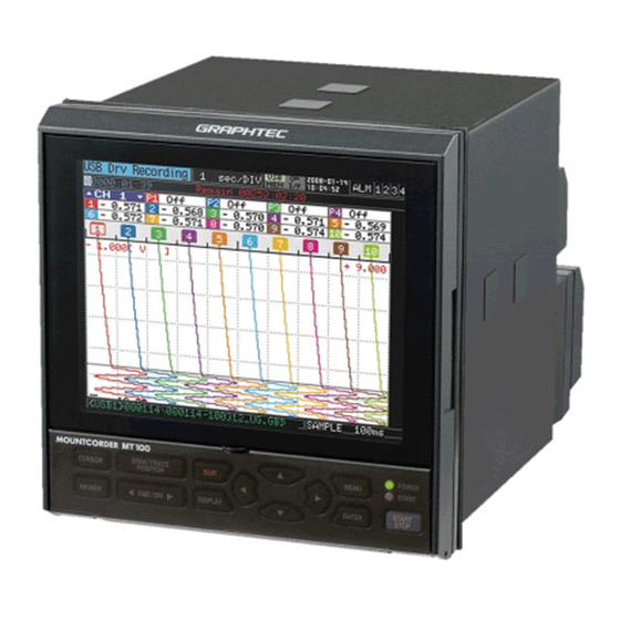
Page 4: Mt100 Part Names And Functions
1. MT100 Part Names and Functions Front Front panel Monitor Control panel cover Opening the Control Panel Cover As shown in the following figure, hold the tab in the center of the control panel cover and pull it in the direction indicated by an arrow to open the cover. - Page 5 Pull the part indicated by an arrow in the following figure to open the front panel. Front panel Power switch USB memory terminal Maximum Dimensions of USB Memory The maximum dimensions of USB memory that can be attached to the MT100 are shown in the following figure. 21.5mm 47mm Front 90mm 13mm 8.5mm...
-
Page 6: Rear
Rear Ethernet terminal USB terminal Power jack for the humidity sensor Power terminal and protective ground terminal External input/output terminal LOGIC/PULSE EXT TRIG ALARM Analog signal input terminals Removing the Terminal Cover While applying force in direction A, pull the cover in direction B to remove the cover. (The external input/output terminal cover can also be removed in the same way.) -
Page 7: Installation Procedure
Installation Procedure As the panel, use a steel sheet 2mm to 26mm in thickness. Use the panel mount brackets provided with the MT100 to attach it. There are two panel mount brackets. Be sure to attach them in two opposite locations (up and down or left and right). -
Page 8: Connecting To An Ac Power Supply
(for 4mm screws) inserted in insulation caps. In the power line, provide a switch that can cut off the MT100 from the main power source (double-pole type). As specifications of the switch, the rated steady-state current must be 1A or larger and the rated inrush current must be 60A or larger. -
Page 9: Connecting Signal Input Cables
Therefore, fix the wiring cords to the back of the installed panel. To prevent fire, use signal cables with a rated temperature of 70°C or higher. Do not apply a voltage higher than the following values to input terminals. If you do, the MT100 may suffer damages. -
Page 10: Connecting Cables To Digital Input And Alarm Output Terminals
Therefore, fix the wiring cords to the back of the installed panel. To prevent fire, use signal cables with a rated temperature of 70°C or higher. Do not apply a voltage higher than the following values to input terminals. If you do, the MT100 may suffer damages. -
Page 11: Precautions To Observe When Performing Measurement
(see the following figure). Example 3: Set the filter to other setting than OFF in the AMP setup menu. Example 4: Set a sampling interval at which the digital filter of the MT100 is effective (500ms or more). To be connected to the... -
Page 12: Initial Setup
To change the setting later, open OTHR menu and select Language. Setting the Date and Time If you are using the MT100 for the first time, charge the internal rechargeable battery and then make the date and time settings. CAUTION If the MT100 is not used for a period of approximately six months, the internal rechargeable battery may be discharged and the date and time may revert to the initial settings. -
Page 13: Window Names And Functions
Internal memory is being accessed. CAUTION Do not turn off the power of the MT100 while the USB memory or internal memory is being accessed. If you do, data may be corrupted and you may no longer be able to access the memory. - Page 14 Measurement data display <Waveform scrolling direction: Vertical > <Waveform scrolling direction: Horizontal > Data capture bar Digital display Pen display Waveform display (Present) Compressed waveform display (Past) Sampling interval display File name display Data capture bar During data capture, indicates capturing time and the remaining capacity of the capture media. (When the remaining capacity runs short, the display changes into orange.) During replay, indicates information about the displayed position.
-
Page 15: Key Operation
10. Key Operation (1) CURSOR (4) Direction Keys (2) SPAN/TRACE/POSITION (3) QUIT (5) MENU (6) START/STOP (8) DISPLAY (7) ENTER (9) TIME/DIV (10) REVIEW (1) CURSOR (ALM CLR) This key has different roles according to the operation status. During replay: This key is used to toggle between cursors A and B displayed during replay. During free-running and data capture: When the alarm setting is “Hold generated Alarm”, the maintained alarm is cleared. - Page 16 (The screen is shown in the following figure.) CAUTION To exit USB Drive Mode, turn the power off and then on. When the MT100 is used in USB Drive Mode, no user operation is allowed, including data capturing and data replay. (7) ENTER...
- Page 17 (8) DISPLAY This key is used to switch the data display mode. You can switch the display mode during free running (when stopped) and data capturing. Pressing this key switches the display mode as follows: Waveform + Digital Screen Displays waveforms and digital values. This is the initial screen at power-on.
-
Page 18: Setting Examples
11. Setting Examples (Example 1) Enabling temperature measurement using thermocouples for all the channels Press the MENU key to open the AMP menu. Use the key to move the cursor to ALL Input. Press the ENTER key to select TEMP. Press the key to select ALL Range. -
Page 19: (Example 2) Storing Captured Data In Usb Memory
(Example 2) Storing captured data in USB memory This setting allows you to store captured data with an automatically generated file name in USB memory. * Attach the USB memory to the MT100 before making this setting. Press the MENU key to open the DATA menu. -
Page 20: (Example 3) Replaying Captured Data
(Example 3) Replaying captured data This section explains how to replay captured data. Press the REVIEW key to open the Data Replay Select File and press the ENTER key to open the Source menu. file selection menu. Press the key to go into a folder. Select a file to be replayed and press the ENTER key. -
Page 21: Specifications
Ethernet (10BASE-T/100BASE-TX) USB (FullSpeed) Ethernet functions Web server function: Displays MT100's screen image on Web browser, operation of MT100 (10BASE-T/100BASE-TX) FTP server function: Transfers and deletes files from internal memory and USB memory FTP client function: Supports backup of data in internal and USB memory... - Page 22 Input unit specifications: Item Description Number of input channels 10 ch Input terminal type M4 screw type terminals Input method Photo MOS relay scanning system All channels isolated, balanced input Scan speed 0.1s/10 ch maximum Measurement Voltage 20, 50, 100, 200, 500mV; 1, 2, 5, 10, 20, 50V; 1-5 V F.S. ranges Temperature Thermocouples: K, J, E, T, R, S, B, N, W (WRe5-26)
Need help?
Do you have a question about the MT100 and is the answer not in the manual?
Questions and answers