
Related Manuals for Zte R800


Summary of Contents for Zte R800
- Page 1 R800 R800 LTE R NDUSTRY GRADE OUTER ANDBOOK Website: www.Vlink.com E-mail: Vlink@zte.com.cn...
- Page 2 Without the prior written permission of ZTEWelink, no entity or individual is allowed to reproduce, transfer, distribute, use and disclose this document or any image, table, data or other information contained in this document. ZTEWelink is a holding subsidiary of ZTE Corporation, dedicate to cellular M2M communication modules and M2M solutions. &...
- Page 3 R800 HANDBOOK COPE OF PPLICATION Industry-grade Wireless Router R800-U for North American R800-J for Japan and Korea R800-C for China R800-F for China Private Network R800-E for Europe EVISION ISTORY Version Date Description V1.0 2016-12-10 First issue BOUT THIS OCUMENT...
-
Page 4: Table Of Contents
ARDWARE TRUCTURE 2.1.1. Device Appearance and Dimensions............................4 2.1.2. Packing List....................................4 .................................5 2.2. F UNCTIONAL LOCK IAGRAM 3. R800 LTE ROUTER INSTALLATION................................6 ....................................6 BOUT THIS HAPTER ......................................6 3.1. U NPACKING ................................6 3.2. I NSTALLATION AND ONNECTION 3.2.1. - Page 5 R800 HANDBOOK ..................................41 5.4. VPN C ONFIGURATION 5.4.1. Overview....................................43 5.4.2. VPDN Configuration................................43 5.4.3. N2N_V2 Configuration................................45 5.4.4. OPENVPN....................................46 5.5. F ................................51 ORWARDING ONFIGURATION 5.5.1. Overview....................................51 5.5.2. NAT......................................51 5.5.3. Route Configuration................................53 5.5.4. DMZ......................................55 ..................................55 5.6. S ECURITY ONFIGURATION 5.6.1.
-
Page 6: Introduction
1.1. Overview R800 LTE Router supports such 4G network architectures as TDD LTE and FDD LTE, and such 3G+ network architectures as HSPA+, and such 3G network architectures as TD-SCDMA, EVDO and WCDMA. It has downward compatibility with such 2G network architectures as GPRS\CDMA. -
Page 7: Functions And Characteristics
Security Access Communication R800 LTE Router supports transmission of videos and pictures, and can be connected with the access monitoring device at the security access. Based on 3G/4G wireless communication, R800 LTE Router transmits the picture taken by the monitoring device to the designated server, so as to easily realize transmission of monitoring data of different road sections. - Page 8 R800 HANDBOOK CDMA 1x Network standard IEEE 802.11n IEEE 802.3 IEEE 802.3u Device interface 3G/3G+/4G LTE antenna interface: SMA-K (inner nut needle) Wi-Fi antenna interface: SMA-K (SMA inner nut needle) Module: built-in 2G/3G/4G LTE module (upgradable and replaceable) ...
-
Page 9: Product Structure
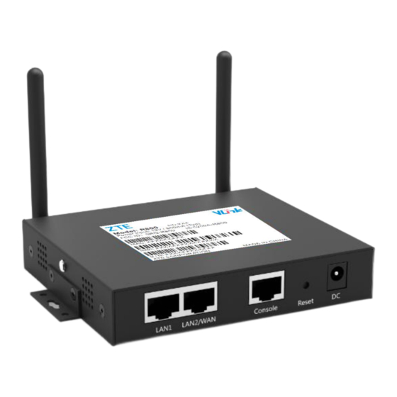
2.1.1. D EVICE PPEARANCE AND IMENSIONS External View See Figure 2-1-1 for the physical appearance of Vlink R800 LTE Router. Figure 2-1-1 Physical Appearance of R800 LTE Router Table 2-1-1 Device Dimensions of R800 LTE Router Name of Device Socket Description L×W×H(mm) -
Page 10: Functional Block Diagram
Serial port (UART data processing module The serial port of R800 LTE Router mainly serves to transmit data between the router and the serial port device. LAN/WAN port data processing module When the LAN/WAN port of the router is used as LAN port, the data processing module communicates with the lower computer through RJ45 cable and enables the lower computer to serve the function of IP data forwarding. -
Page 11: R800 Lte Router Installation
This section describes R800 LTE Router unpacking and the packing list check. 3.2 Installation and Connection This section describes the installation of SIM card of R800 LTE Router and its connection with Ethernet port and serial port cable, etc. 3.3 Power Supply This section describes the requirement and method of power supply for R800 LTE Router. -
Page 12: Ethernet Cable Connection
ERIAL ABLE ONNECTION R800 LTE Router supports serial port DTU function. When you need to use this function, connect your device with RJ45 by ways of the serial port. 3.3. Power Supply R800 LTE Router can be applied in complicated conditions, and the power supply can be 12V DC. -
Page 13: Installation Check
Step 2 Check whether SIM card is installed in a correct manner, and confirm whether it is valid. Step 3 Supply power to R800 LTE Router. If the light of the LAN port connected with the lower computer is on when R800 LTE Router is energized, it means the ... -
Page 14: Pre-Configuration Preparation
4.1. Status of Indicator Light on Terminal Panel There are eight LED indicator lights on the front panel of R800 LTE Router, indicating the working condition and network condition of R800 LTE Router. See Table 4-1-1 for indicator light status description. - Page 15 R800 HANDBOOK Figure 4-2-1 Network Connection Window Step 2: Double click on “Local Area Connection”, and open the window “Local Area Connection Status”. See Figure 4-2-2. Figure 4-2-2 Local Area Connection Status Step 3: In the window “Local Area Connection Status”, click “Attributes” to open the window “Local Area Connection...
- Page 16 In the window “Local Area Connection Attributes” , double click on “Internet Protocol (TCP/IP)” , and open the window “Internet Protocol (TCP/IP) Attributes”. Revise the general network configuration in the option “General”. See Figure 4-2-4. Figure 4-2-4 General Network Configuration Among factory default parameters of R800 LTE Router, IP address: 192.168.1.1 ...
- Page 17 This method is based on the existing network environment configuration (Step 1~Step 3); where it is not desired to disconnect LAN communication of PC and it is desired to have R800 LTE Router configured, a router can be additionally provided.
- Page 18 R800 HANDBOOK Figure 4-2-7 Network Connection Window Step 2: Right click on “Local Area Connection 2” , and click “Attributes” in the popup menu; open the window “Local Area Connection 2”. See Figure 4-2-8. Figure 4-2-8 Local Area Connection Attributes Step 3: In the window “The Connection Uses the Following Item (O)”, click “Internet Protocol (TCP/IP)”, and double click to...
- Page 19 R800 HANDBOOK Figure 4-2-9 Internet (TCP/IP) Attributes Step 4: If“Internet Protocol (TCP/IP) Attributes”is as Figure 4-2-9 shows, then no alteration is required; if not, select“Obtain an IP Address Automatically” in “General”. In the window “The Connection Uses the Following Item (O)”, click “Internet Protocol (TCP/IP)”, and double click to open the window “Internet Protocol (TCP/IP) Attributes”.
- Page 20 R800 HANDBOOK Figure 4-2-10 “Running” Window Step 7: Insert the command “ipconfig” in the “Running” window. For the above two connection configuration methods, the IP address showed in the “ipconfig” window is different: for the former, IP address is the IP address you insert in Figure 4-2-4;...
- Page 21 Step 8 Insert the following command in the command window to confirm whether it is well connected. If ping 192.168.1.1 shows the interface as Figure 4-2-13, it means the connectivity of local computer with R800 LTE Router is normal. Figure 4-2-13 Verification result...
-
Page 22: Router Configuration
R800 LTE Router configuration can be done in a WEB-based manner. Configuration in a WEB-based manner is simple and direct. After local area connection of PC with R800 LTE Router is completed according to “ 4.2 Local Area Connection Configuration ” , chrome browser can be started;... -
Page 23: Network Configuration
Step 1: Login to WEB configuration interface of R800 LTE Router. Please refer to “5.2.1 Login to WEB Configuration Interface”. Step 2: Click “Network Setting>LAN”. Open the tab “LAN”. See Figure 5-2-2. - Page 24 It is mainly used to connect Internet through Ethernet. There are three major connection types: Static IP, DHCP and PPPoE. Step 1: Login to WEB configuration interface of R800 LTE Router. Please refer to “5.2.1 Login to WEB Configuration Interface”.
- Page 25 ETWORK This is one of the core functions of R800 LTE Router. The router connects Internet through modem dial-up, providing users with the function of high-speed wireless broadband Internet. 3G network speed can often be 1 ~ 5Mbps, while 3.5G network speed reaches up to 20Mbps;...
- Page 26 R800 HANDBOOK Table 5-2-3 “Mobile Network” Parameter Description Parameter Description Configuration Invocation MODEM dialing A kind of code identification of network, usually one kink of CODE type, usually 64 bytes at maximum, please refer network system has its fixed service code, such as GSM table 5-2-2 to see parameter description.
- Page 27 ONFIGURATION R800 LTE Router provides AP mode and client mode. With the former, R800 LTE Router can provide you with LAN hotspot for Internet access, which saves the trouble of connections. With the latter, you can have R800 LTE Router connected with other device, so that the lower computer of R800 LTE Router can have access to outer net through the connected AP device.
- Page 28 R800 HANDBOOK Figure 5-2-6 WALN Tab Select the first one, click “Edit” to enter the edition interface. See Figure 5-2-7. Figure 5-2-7 AP Mode Tab...
- Page 29 R800 HANDBOOK Figure 5-2-8 Client Mode Tab Figure 5-2-9 AP Scanning Tab Step 3: Configure “WLAN” parameters. See Table 5-2-5 for parameter description.
- Page 30 R800 HANDBOOK Table 5-2-5 WLAN Parameter Description Name of Parameter Meaning Configuration Enable Enable WLAN function Button option Enable Disable Operating mode Operating mode of WLAN; support ap mode /client mode. Drop-down box options Access Point(AP) Client mode ...
- Page 31 IP automatically, which saves the trouble of changing local IP once the gateway changes. Step 1: Login to WEB configuration interface of R800 LTE Router. Please refer to “5.2.1 Login to WEB Configuration Interface”. Step 2: Click “Network Configuration > DHCP Service”. Open the tab “DHCP Service”, see Figure 5-2-10.
- Page 32 R800 HANDBOOK Figure 5-2-10 DHCP Service Tab Step 3: Configure “DHCP Server Configuration”. See table 5-2-6 for DHCP server configuration parameters. Table 5-2-6 DHCP Server Configuration Parameter Description Parameter Meaning Setting Enable Use DHCP function Button option Enable Disable ...
-
Page 33: Application Configuration
ICMP links detection is mainly used for the detection of wireless links at the earlier design stage, and R800 LTE Router supports the detection of VPN tunnel links and detection with multiple rules, which has... - Page 34 R800 HANDBOOK Step 1: Log onto the WEB configuration interface of R800 LTE Router as provided in “5.2.1 Log onto the WEB Configuration Interface”. Step 2: Click“Application Configuration > Online Maintenance”to open the“ICMP Detection”tab, as shown in Figure 5-3-1. Figure 5-3-1 Online Maintenance Tab Step 3: Configure the Online Maintenance parameters, as shown in Table 5-3-1.
-
Page 35: Network Management Configuration
WMMP Protocol (Wireless Machine-to-Machine Protocol) and M2M (Machine-to-Machine) platform communications. Specific settings are as follows. Step 1: Log onto the WEB configuration interface of R800 LTE Router as provided in “5.2.1 Log onto the WEB Configuration Interface”. -
Page 36: Dtu Configuration
IP data or transform IP data to serial port data and transfer it through the wireless communication network). Specific settings are as follows. Step 1: Log onto the WEB configuration interface of R800 LTE Router as provided in “5.2.1 Log onto the WEB Configuration Interface”. - Page 37 R800 HANDBOOK DTU Advanced Configuration Step 3: If you want to work in the server working mode of the DTU, configure the parameters for the DTU in the working server mode, as shown in Table 5-3-3. Table 5-3-3 DTU Parameters...
-
Page 38: Ddns Settings
Step 1: Log onto the WEB configuration interface of R800 LTE Router as provided in “5.2.1 Log onto the WEB Configuration Interface”. - Page 39 R800 HANDBOOK Figure 5-3-3 DDNS Settings Tab Step 3: Configure the DDNS service parameters, as shown in Table 5-3-4. Table 5-3-4 DDNS Service Parameters Parameter Name Meaning How to Configure To enable the DDNS service. DDNS Service Press the button to select.
- Page 40 R800 HANDBOOK selfhost.de no-ip.pl domains.google.com CloudFlare Username/Password Username and Password used to register the domain name Generally WORD type/CODE type, with a Max of 64 provided by the DDNS service provider. bytes. Domain Name Domain name provided by the DDNS service provider, Generally WORD type, with a Max of 64 bytes.
- Page 41 R800 HANDBOOK Figure 5-3-4 Portal Step 3 configure Portal parameters, the following table is the parameter description: Table 5-3-5 Portal Parameter Description Parameter Name Meaning How to Configure Enabled Enable Portal function Click button to select Enable Disable Gateway ID Set gateway ID, the specified devices that server can Normally word type, 64 bytes at most.
-
Page 42: Traffic Statistics Settings
SIM card's over traffic. At the beginning of every month, the used traffic will be cleared. Step 1: Log onto the WEB configuration interface of R800 LTE Router as provided in “5.2.1 Log onto the WEB Configuration Interface”. -
Page 43: Qos Settings
ETTINGS The QOS is mainly used to control and distribute the bandwidth for downloading and uploading as demanded. Step 1: Log onto the WEB configuration interface of R800 LTE Router as provided in “5.2.1 Log onto the WEB Configuration Interface”. -
Page 44: Timed Tasks Configuration
(such as a few Hrs of a day) depending on their needs and have task executed at specific points in time (such as to re-dial up or reboot the system at 0 midnight every day). Step 1: Log onto the WEB configuration interface of R800 LTE Router as provided in “5.2.1 Log onto the WEB Configuration Interface”. - Page 45 R800 HANDBOOK Figure 5-3-8 Timing Rule Settings Tab Configure the QOS parameters, as shown in Table 5-3-7. Table 5-3-8 QOS Parameters Parameter Name Meaning How to Configure Points in time when used a. Directly input values are points in time,...
- Page 46 SNMP protocol is supported by router. By this protocol, users can check the device temperature information. The following is the configuration step: Step 1: Log onto the WEB configuration interface of R800 LTE Router as provided in “5.2.1 Log onto the WEB Configuration Interface”.
- Page 47 The following is the configuring step: Step 1: Log onto the WEB configuration interface of R800 LTE Router as provided in “5.2.1 Log onto the WEB Configuration Interface”.
-
Page 48: Vpn Configuration
Log onto the WEB configuration interface of R800 LTE Router as provided in “5.2.1 Log onto the WEB Configuration Interface” . Step 1: Click “VPN Settings > VPDN Configuration”. - Page 49 R800 HANDBOOK Figure 5-4-2 VPDN Configuration Tab Step 4: Configure the VPDN rule parameters, as shown in Table 5-4-1. Table 5-4-1 VPDN Rule Parameters Parameter Name Meaning How to Configure Enable To enable VPN connections. Press the button to select.
-
Page 50: N2N_V2 Configuration
To make it simple, it requires no public IP or configuration of the NAT, but penetrates the firewall. Log onto the WEB configuration interface of R800 LTE Router as provided in “5.2.1 Log onto the WEB Configuration Interface” . -
Page 51: Openvpn
R800 HANDBOOK Figure 5-4-3 N2N_v2 Configuration Tab Table 5-4-2 N2N_v2 Parameters Parameter Name Meaning How to Configure Enable To enable N2N_v2 connections. Press the button to select. Enable Disable Local IP To set an intranet IP address Manual input. - Page 52 R800 HANDBOOK Log onto the WEB configuration interface of R800 LTE Router as provided in “5.2.1 Log onto the WEB Configuration Interface” . Step 1: Click “VPN Settings > OPENVPN”. Step 2: Open the “OPENVPN” tab, as shown in Figure 5-4-4 and Figure 5-4-5. See Table 5-4-3 for the parameters.
- Page 53 R800 HANDBOOK Figure 5-4-5 OPENVPN Advantage Tab Table 5-4-3 N2N_v2 Parameters Parameter Name Meaning How to Configure Enable To enable OPENVPN connections. Press the button to select. Enable Disable Server IP Server IP address for access. Enter the server IP address for access.
- Page 54 Transport Layer (TLS) and the Application layer (SSH). Hence, only IPsec protects all application traffic over an IP network. IPsec can automatically secure applications at the IP layer. Step 1: Log onto the WEB configuration interface of R800 LTE Router as provided in “5.2.1 Log onto the WEB Configuration Interface”.
- Page 55 R800 HANDBOOK Figure 5-4-7 Encryption Tab The related parameter descriptions are in the following table: Table 5-4-4 IPSEC Parameter Description Parameter Name Meaning How to Configure Enabled Enable IPSEC Press the button to select. Enable Disable Negotiation model IPSec negotiation mode in first stage, includes“...
-
Page 56: Forwarding Configuration
5.5. Forwarding Configuration 5.5.1. O VERVIEW R800 LTE Router has forwarding functions include NAT, static routing, DMZ. 5.5.2. NAT NAT (Network Address Translation) is generally used to replace a private network (LAN) IP address with an IP address in the... - Page 57 R800 HANDBOOK Step 1: Log onto the WEB configuration interface of R800 LTE Router as provided in “5.2.1 Log onto the WEB Configuration Interface”. Step 2: Click “Forwarding Settings > NAT” to open the “NAT” tab, as shown in Figure 5-5-1.
-
Page 58: Route Configuration
Step 1: Log onto the WEB configuration interface of R800 LTE Router as provided in “5.2.1 Log onto the WEB Configuration Interface”. Click “Forwarding Settings > Route Configuration”, as shown in Figure 5-5-3. - Page 59 R800 HANDBOOK Figure 5-5-4 Static Routing Configuration Page See Table 5-5-2 for the parameters. Table 5-5-2 Route Configuration Parameters Parameter Name Meaning How to Configure Interface Name To specify the logical interface name of the routing Choose in the drop-down list: as a parent (or primary) interface ...
-
Page 60: Dmz
R800 LTE Router supports IP filtering and MAC address filtering, which are enabled by setting security rules, such as allowing/disallowing some network segments to access the WAN and allowing/disallowing other users to access the router. -
Page 61: Ip Filtering
Internet access of the LAN devices. IP filtering is generally used to allow some of the hosts to access the WAN or disallow some of the hosts to access a specific network. Step 1: Log onto the WEB configuration interface of R800 LTE Router as provided in “5.2.1 Log onto the WEB Configuration Interface”. - Page 62 R800 HANDBOOK Figure 5-6-3 Create/Edit Tab...
- Page 63 R800 HANDBOOK Figure 5-6-4 User-Defined Effective Time Table 5-6-1 for the parameters. Parameter Meaning How to Configure Name Action Action to packets matching the rules Choose in the drop-down list: ACCEPT ACCEPT REJECT REJECT DROP DROP ...
-
Page 64: Mac Filtering
ILTERING MAC filtering, matched with the MAC in the data packets, processes the data packets. Step 1: Log onto the WEB configuration interface of R800 LTE Router as provided in “5.2.1 Log onto the WEB Configuration Interface”. Step 2: Click “Security Settings > MAC Filtering” to open the “MAC Filtering” tab, as shown in Figure 5-6-4. - Page 65 R800 HANDBOOK Figure 5-6-5 MAC Filtering Tab Click “Create” to create a new rule, as shown in Figure 5-6-5. Figure 5-6-6 Create Tab See the table below for the parameters. Figure 5-6-2 MAC Filtering Parameters Parameter Name Meaning How to Configure...
-
Page 66: System Management Configuration
You can perform systematic daily maintenance operations after having an understanding of the system management functions of R800 LTE Router, such as running of the log analysis system, management of the user account information, network testing and upgrade of the system files. -
Page 67: Configuration Management
ANAGEMENT Configuration management enables the user to import or export configuration and restore to the factory default configuration. Step 1: Log onto the WEB configuration interface of R800 LTE Router as provided in “5.2.1 Log onto the WEB Configuration Interface”. -
Page 68: Firmware Upgrade
R800 LTE Router supports upgrading the system file with the local network. Before upgrading, make sure that you have obtained the target update file of the system and placed the update file in the LAN computer. Step 1: Log onto the WEB configuration interface of R800 LTE Router as provided in “5.2.1 Log onto the WEB Configuration Interface”. - Page 69 Upon upgrade, refresh the page and log onto WEB. System Debugging Step 1: Log onto the WEB configuration interface of R800 LTE Router as provided in “5.2.1 Log onto the WEB Configuration Interface”. Step 2: Click “System Management > System Debugging” to show the “System Debugging” interface, as shown below.
- Page 70 Telnet is the telnet server. Enable telnet to log on to the command line of the device for operation through telnet. Step 1: Log onto the WEB configuration interface of R800 LTE Router as provided in “5.2.1 Log onto the WEB Configuration Interface”.
- Page 71 Network Testing Tool Network testing, includes Ping and Traceroute, is used in the specific steps as follows: Step 1: Log onto the WEB configuration interface of R800 LTE Router as provided in “5.2.1 Log onto the WEB Configuration Interface”. Step 2: Click “System Management > Network Testing” to open the “Network Testing” tab, as shown in Figure 5-7-8.
- Page 72 System Time Set the system time of R800, default configuration is network synchronization, also can set it manually. Step 1: Log onto the WEB configuration interface of R800 LTE Router as provided in “5.2.1 Log onto the WEB Configuration Interface”.
- Page 73 EBUG Debug Step 1: Log onto the WEB configuration interface of R800 LTE Router as provided in “5.2.1 Log onto the WEB Configuration Interface”. Step 2: Click “System Management >Debug” to open the “Debug” tab, as shown in Figure below: Step 3 click “Refresh”can check the current debug information, if you want to check the other debug information, please see...
- Page 74 Telnet When enable Telnet function, command can be done via Telnet. Step 1: Log onto the WEB configuration interface of R800 LTE Router as provided in “5.2.1 Log onto the WEB Configuration Interface”. Step 2: Click “System Management >Telnet” to open the “Telnet” tab, as shown in Figure below:...
- Page 75 Module Log Export module log. Step 1: Log onto the WEB configuration interface of R800 LTE Router as provided in “5.2.1 Log onto the WEB Configuration Interface”. Step 2: Click “System Management >Module log” to open the “Module log” tab, as shown in Figure below:...
- Page 76 Network Tool Network test, includes Ping function and Traceroute function: Step 1: Log onto the WEB configuration interface of R800 LTE Router as provided in “5.2.1 Log onto the WEB Configuration Interface”. Step 2: Click “System Management >Network tool” to open the “Network tool” tab, as shown in Figure below:...
- Page 77 Temperature Alarm Configure the temperature value to send a alarm, should be connected to LED indicator alarm. Step 1: Log onto the WEB configuration interface of R800 LTE Router as provided in “5.2.1 Log onto the WEB Configuration Interface”. Step 2: Click “System Management >Temperature Alarm” to open the “Temperature Alarm” tab, as shown in Figure below:...
-
Page 78: State
Through state check, you can quickly grasp the basic information, network status of R800 LTE Router and the routing status information. 5.8.2. B ASIC NFORMATION You can learn the basic information of the R800 LTE Router system by viewing the basic information of R800 LTE Router, as shown below. -
Page 79: Lan State
5.8.3. LAN S TATE You can learn the basic information of the "LAN State" of the R800 LTE Router system by viewing the "LAN State" information of R800 LTE Router, as show below. Step 1: Log onto the WEB configuration interface of R800 LTE Router as provided in “5.2.1 Log onto the WEB Configuration Interface”. -
Page 80: Wan State
5.8.4. WAN S TATE You can learn the basic information of the "WAN State" of the R800 LTE Router system by viewing the "WAN State" information of R800 LTE Router, as show below. Step 1: Log onto the WEB configuration interface of R800 LTE Router as provided in “5.2.1 Log onto the WEB Configuration Interface”. -
Page 81: Wlan
Interface". Step 2: Click “ State > WLAN State ” . The WLAN of H8 R800 922 4G Router has two modes, ap and client with the basic information in each mode as shown in Figure 5-8-4 and Figure 5-8-5. See Table 5-8-4 and Table 5-8-5 for the parameters. -
Page 82: Mobile Network State
State to determine whether the network and the device are normal to analyze abnormal situations and solve the relevant problems. Step 1 Log onto the WEB configuration interface of R800 LTE Router as provided in "5.2.1 Log onto the WEB Configuration Interface". -
Page 83: Reset Button
R800 HANDBOOK Subnet Mask Subnet mask of the WAN obtained over dial-up by R800 LTE Router. Unmatchable Address IP address of the WAN obtained over dial-up by R800 LTE Router. Gateway Unmatchable DNS1 Unmatchable DNS2 Unmatchable 5.9. RESET Button The "RESET" button is located at the power supply interface of the rear panel of the device and can be used when the device is normally functioning and the device energized. -
Page 84: Typical Applications
Scenario Introduction R800 LTE Router supports task management by sending some instructions from the WEB page to the router including reboot and online to enable the router to perform these actions within a specified time. Task management can readily enable the router to perform some routine functions, in order to save artificial operations. -
Page 85: Dtu Functional Application
The DTU server may be connected to the public network (by mapping the router address to the DTU server through the NAT), with the TCP enabled on the server, R800 LTE Router as the TCP client and the DTU serial device to receive and send data. - Page 86 R800 HANDBOOK Figure 6-3-2 DTU Client (R800 LTE Router) Configuration Figure 6-3-3 DTU Server Configuration...
- Page 87 R800 HANDBOOK Application Results Communication between the DTU server and the client are as shown in Figure 6-3-4: the client sends 200 bytes of data packets to the server and the server sends 100 bytes of data packets to the client.
Need help?
Do you have a question about the R800 and is the answer not in the manual?
Questions and answers