Table of Contents
Advertisement
Advertisement
Table of Contents

Subscribe to Our Youtube Channel
Related Manuals for Dynatronics dynatron solaris 709 plus


Summary of Contents for Dynatronics dynatron solaris 709 plus
- Page 1 DYNATRON SOLARIS PLUS SERIES | SERVICE MANUAL REV. 6 | AUGUST 29, 2017 ®...
-
Page 2: Indications For Use
THERMOSTIM: A hand held cutaneous electrode to be used with Dynatronics Solaris devices to apply electrical stimulation and/or apply heat and cooling to skin. - Page 3 Table of ConTenTs Table of Contents Section I: Introduction Introduction to the Dynatron Solaris® Plus Series ................1 Summary of Features by Device ...............................1 Simplified Setup ..................................2 Language Selection ..................................3 Before You Treat a Patient .................................3 Installation and Features ........................4 Unpacking ....................................4 Standard Components ................................5 Optional Accessories .................................6...
- Page 4 Table of ConTenTs Detailed Interferential / Premodulated Setup ........................27 Interferential and Premodulated Modality Information ..............31 Interferential (Quadpolar) Therapy ............................31 Premodulated (Bipolar) Therapy ............................32 Target ......................................32 Why Is Target Better? ................................32 Target Sweep .....................................33 Interferential Electrode Placement ............................33 Interferential / Premodulated Default Settings ........................33 Interferential Default Settings ..............................33 Premodulated Default Settings...............................33 Biphasic / Russian Instructions ......................
- Page 5 Table of ConTenTs Direct Current Modality Information ....................61 Direct Current Probe Therapy ..............................61 Direct Current Waveforms ..............................61 Direct Current Warnings ................................62 Direct Current Default Setting ...............................62 Dynatron Tri-Wave™ Operating Instructions ..................63 Dynatron Tri-Wave™ Light Quick Treatment Setup ......................64 Detailed Treatment Setup ...............................65 Dynatron Tri-Wave™...
- Page 6 Table of ConTenTs Ultrasound Beam Profiles ........................89 Combination Therapy Instructions ..................... 91 Comboplus™ ....................................91 Stim Through the Soundhead ..............................92 Combination Therapy Setup ..............................93 Modify A Treatment ................................94 Combination Default Settings ..............................94 Dynatron® ThermoStim™ Probe ......................95 Functionality .....................................95 ThermoStim Probe Detailed Setup ............................96 Using Stim With The ThermoStim Probe Premod Treatments Setup ..............................100 Simultaneous Treatments ........................
- Page 7 Table of ConTenTs Section IV: Technical Information Dynatron Solaris® Plus Descriptions and Diagrams ................. 116 Dynatron® Solaris™ Plus Description ...........................116 Hardware Configurations ..............................117 Modality Configurations ...............................117 Processor Interaction ......................... 118 Processor Interaction with the Keyboard and Displays ....................118 Processor Interaction with Oscillators ..........................118 Oscillators ....................................118 Processor Interaction with the Output Jacks ........................119 Processor Control of Output Waveforms ...........................119...
- Page 8 Table of ConTenTs Electromagnetic Emissions and Immunity ..................142 Final Quality Check (QC) Checkoff Sheet ..................146 Dynatron Solaris Plus Limited Warranty ..................150 ® DYNATRON SOLARIS PLUS SERIES | SERVICE MANUAL REV. 6 | AUGUST 29, 2017 VIII ®...
-
Page 9: Introduction To The Dynatron Solaris® Plus Series
Interferential, Premodulated, High Volt, Biphasic, Russian, Microcurrent, and fixed frequency IFC/Premod. All units, excluding the 707, also offer Direct Current. In addition, the 708 and 709 include Dynatronics’ Ultrasound Comboplus feature with the power to deliver up to 5 channels of Stim and Ultrasound—all at the same time. The 708 and 709 Ultrasound units also offer 1, 2, and 3 MHz frequencies for the greatest flexibility in depth of treatment. -
Page 10: Simplified Setup
Tri-Wave light Pad Channels Thermostim Channels The Solaris Plus Series includes the standard advantages of Dynatronics’ engineering, such as customizable treatments, electrode conductance meters, and the popular Target touchpad to move the center of interference directly to the site of the patient’s pain. -
Page 11: Language Selection
InTroduCTIon To The dynaTron solarIs® Plus serIes Language Selection The default language on the Solaris Plus Family of devices is English; however, both French and Spanish are also available. To change the default language: 1) Begin at the START UP SCREEN. 2) Press the FUNCTION KEY. 3) Use the toggle key under the LANGUAGE WINDOW to select the desired language. -
Page 12: Installation And Features
Complete the warranty registration form located at the back of this manual and return it to Dynatronics within 30 days of purchase. This is essential to insure you are not billed for services that are covered by the warranty policy. Warranty registration should include serial numbers for both the device, probe, pads, and soundheads. -
Page 13: Standard Components
InsTallaTIon and feaTures Standard Components The following accessories are included with the Solaris Plus units: Part No. Description: One of the following devices plus acessories as listed: D715 Solaris Plus 705 D716 Solaris Plus 706 D717 Solaris Plus 707 D718 Solaris Plus 708 D719 Solaris Plus 709... -
Page 14: Optional Accessories
InsTallaTIon and feaTures Optional Accessories The following optional and replacement accessories may be purchased from Dynatronics or from your Dynatronics dealer: Part No. Description DCP3 Dynatron Tri-Wave™ Light Probe DLP3 Dynatron Tri-Wave™ Light Pads DSTP1 Dynatron ThermoStim™ Probe (includes Combo Lead) -
Page 15: Dynatron Solaris® Plus Physical Features
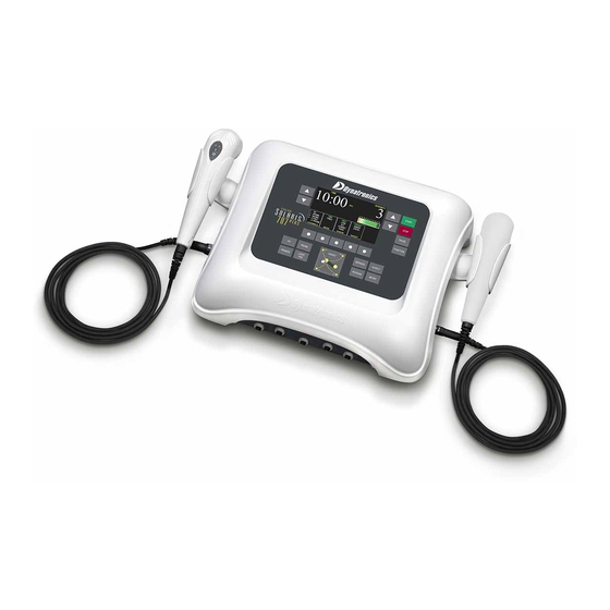
dynaTron solarIs® Plus PhysICal feaTures Dynatron Solaris Plus ® Physical Features Before operating the Dynatron Solaris Plus devices, acquaint yourself with the control panel by reviewing the illustrations and descriptions on the following pages. The numbered features in the diagrams correspond to the numbered descriptions. Before administering treatment to a patient, read the sections later in this manual that provide specific instructions for performing treatments, discussions of each modality, definitions of the available options, along with contraindications, warnings, and precautions for all modalities. - Page 16 dynaTron solarIs® Plus PhysICal feaTures 1. START: Press the green START key on the right side of the Treatment Display Screen to start the treatment timer and treatment proceeds as set up. For the Solaris Light and Microcurrent Probe treatments, the START key enables the probe(s) in preparation for the treatment.
- Page 17 dynaTron solarIs® Plus PhysICal feaTures IFC (Interferential) Premod Biphasic Russian MC (Microcurrent) DC (Direct Current) LT PROBE (Tri-Wave Light Probe) LT PAD (Tri-Wave Light Pad) DYNATRON SOLARIS PLUS SERIES | SERVICE MANUAL REV. 6 | AUGUST 29, 2017 ®...
- Page 18 dynaTron solarIs® Plus PhysICal feaTures ThermoStim (Heat) ThermoStim (Cold) SOUND (Ultrasound) SOUND (Function Key View) COMBO (Combination) COMBO (Function Key View) HIVOLT (Hight Volt) HIVOLT (Function Key View) DYNATRON SOLARIS PLUS SERIES | SERVICE MANUAL REV. 6 | AUGUST 29, 2017 ®...
- Page 19 dynaTron solarIs® Plus PhysICal feaTures 9. TREATMENT WINDOW TOGGLE KEYS: TOGGLE KEYS are located below the five TREATMENT WINDOWS. Pressing the Toggle Key directly below a window allows one to choose an output channel, and select treatment parameters for the treatment in focus. A treatment is in focus when the name of the treatment appears in the center of the TREATMENT DISPLAY SCREEN and the name of the modality is highlighted green in the channels window.
- Page 20 dynaTron solarIs® Plus PhysICal feaTures 12. CONDUCTANCE/TEMPERATURE BAR Conductance. The Solaris Plus devices continuously measure conductance during electrical Stim treatments for Interferential, Premod, and Microcurrent to ensure that the treatment outcome is optimal and to minimize the possibility of patient discomfort due to poor conductance and/or changes in current density. As conductance is measured, Solaris Plus displays the results in graph form on the CONDUCTANCE bar located on the right side of the TREATMENT DISPLAY SCREEN.
-
Page 21: Channels And Jacks
dynaTron solarIs® Plus PhysICal feaTures • Check to be sure the snap adapters haven’t fallen off or that the lead wire has not become disconnected from the electrodes or the device. • Make sure carbon electrodes have a secure connection with the pin ends of the leads. Over time the carbon electrodes may become too loose to use safely and the electrodes must be replaced. - Page 22 dynaTron solarIs® Plus PhysICal feaTures 14. Left-Side Panel Jacks Located on the left-side of the Solaris Plus are the “Keyed and Locking” Light Probe and Light Pad jacks. Once the arrows are aligned at the top of both the jack and the connector, they will slide together smoothly and exactly. Do not force the connector or damage to the pins may occur.
-
Page 23: Current Limit
dynaTron solarIs® Plus PhysICal feaTures 16. Back Panel Jacks Back Panel Jacks a. Power 1/0 (ON/OFF) Switch. Located on the back of the unit this switch is labeled “1” and “0. ” Set the switch to “1” for ON; set the switch to “0” for OFF. b. -
Page 24: Error Messages
dynaTron solarIs® Plus PhysICal feaTures CURRENT LIMIT ERROR MESSAGES CAUSE “Cannot start treatment with zero intensity” Intensity not set error 101, error 111, error 120, error 130 “lead error: current too low! lead issue; electrode issue Please check or replace your leads and pads!” error 100, error 110, error 140 lead shorted “lead error: high current delivery detected. -
Page 25: Ultrasound Error Messages
dynaTron solarIs® Plus PhysICal feaTures Ultrasound Error Messages ULTRASOUND ERROR MESSAGES CAUSE “no soundhead connected, no soundhead attached cannot setup ultrasound/combo treatment.” “soundhead is too hot! soundhead is too hot output has been disabled to allow cooling.” “Caution: soundhead is getting hot!” soundhead is getting hot “Thermistor on soundhead is broken! Thermistor on soundhead is broken... -
Page 26: Testing Leads
dynaTron solarIs® Plus PhysICal feaTures Test Leads Daily Lead wires should be tested regularly to ensure they are functioning properly and safely. A simple test performed with the Dynatron Solaris Plus devices makes daily lead testing convenient. Damaged or worn leads should be discarded and replaced. -
Page 27: Carbon Electrodes
3. How to Clean Carbon Electrodes. Carbon electrodes from Dynatronics may be cleaned using a mild soap and a small brush (such as a nail brush). To sterilize, alcohol may be used. They may also be sterilized in an Autoclave. Daily cleaning is recommended... -
Page 28: Self-Adhesive Electrodes
Self-Adhesive Electrodes Dynatronics’ self-adhesive electrodes are intended for multiple but patient specific use due to the danger of cross contamination. Improper use of the electrodes can decrease the life of the electrode and could even result in harm to your patient. - Page 29 dynaTron solarIs® Plus PhysICal feaTures • With this method of re-hydration, after a couple of hours electrodes can regain up to 90 per cent of their original adhesive quality. 2. NEVER use a self-adhesive electrode for more than 15 treatments (maximum). 3.
-
Page 30: Electrotherapy Information And Usage Cautions
eleCTroTheraPy InforMaTIon and usage CauTIons Electrotherapy Information and Usage Cautions The following general cautions are to be observed during Interferential, Premodulated, Russian, Biphasic, High Voltage, and Direct Current stimulation. For Microcurrent electrotherapy, see additional cautions in the Microcurrent Section of this manual. WARNING •... - Page 31 eleCTroTheraPy InforMaTIon and usage CauTIons Current Density This is the amount of current being delivered to the patient divided by the area through which the current is being delivered (the surface area of the electrodes being used). Electrode Condition Worn or dried out electrodes cause the current to concentrate in small areas of the electrode instead being evenly distributed over the entire surface of the electrode.
- Page 32 eleCTroTheraPy InforMaTIon and usage CauTIons Interferential / Premodulated electrode size Maximum recommended Intensity 3" round (7.62cm) 25 - 30 Carbon electrodes 3" x 5" (7.62cm x 12.7cm) 30 - 40 1.75" square (4.45cm) 10 - 15 1.75" x 3.75" (4.45cm x 9.53cm) 25 - 30 self-adhesive 1.25"...
- Page 33 eleCTroTheraPy InforMaTIon and usage CauTIons 4. Some patients tend to be much more sensitive to electrotherapy treatments. On patients with this tendency, treat with reduced intensity and/or shorter treatment times with possibly more frequent treatments, if required. Most reactions are localized and very short-lived, so limiting the exposure should minimize any potential for adverse reactions.
-
Page 34: Interferential / Premodulated Instructions
InTerferenTIal / PreModulaTed InsTruCTIons Interferential / Premodulated Instructions An Interferential treatment uses two channels and four electrodes (channel pairs 1-2 or 3-4). The device will automatically select the first available channel pair when you select IFC. A Premodulated treatment uses one channel and two electrodes. The device will automatically select the first available channel (1, 2, 3, or 4) when PREMOD is selected. -
Page 35: Detailed Interferential / Premodulated Setup
InTerferenTIal / PreModulaTed InsTruCTIons NOTE: Prior to increasing intensity, electrodes must be placed on the patient and the lead(s) attached to the device. Plug the lead(s) into the channel(s) the device selects for this treatment. Consult published sources for electrode placements, treatment settings, and treatment times. - Page 36 InTerferenTIal / PreModulaTed InsTruCTIons NOTE: Make any desired changes to the treatment time before selecting Consecutive. Treatment time changes made after selecting Consecutive will cause the treatment to revert to an ALTERNATING HIGH/LOW treatment. • FIXED. A FIXED treatment automatically defaults to a STATIC setting. Press the toggle key under MODE until FREQ is illuminated.
- Page 37 InTerferenTIal / PreModulaTed InsTruCTIons SWEEP. The interferential current randomly sweeps the treatment area within the electrodes allowing the general area to be bathed with Interferential current. STATIC. The interferential current focuses only on the point where the current between electrodes intersects as it follows the path of least resistance.
- Page 38 InTerferenTIal / PreModulaTed InsTruCTIons 9. STOP. When the treatment time has elapsed, the current to the patient stops and a tone sounds signaling the end of a treatment. Treatments in progress may be stopped at any time using one of the following methods. Stop One Treatment Only.
-
Page 39: Interferential And Premodulated Modality Information
InTerferenTIal and PreModulaTed ModalITy InforMaTIon Interferential and Premodulated Modality Information Interferential (Quadpolar) Therapy Interferential therapy uses four electrodes to deliver two currents, one current with a constant frequency of 4000 Hz and the other current with a variable frequency of 4000 to 4150 Hz. The paths of these two currents cross resulting in a “beat” that produces the therapeutic frequency at the treatment site. -
Page 40: Premodulated (Bipolar) Therapy
(a smaller total coverage area means greater current density at the treatment site). Target The Dynatronics’ TARGET (available for Interferential treatments only) simplifies placing the interferential beat directly on the treatment site. The movement of the finger on the Target paid along with the feedback supplied by the patient allows the user to place the ... -
Page 41: Target Sweep
InTerferenTIal and PreModulaTed ModalITy InforMaTIon Target Sweep The Sweep option literally moves the point of interference inward and outward in a somewhat spiral pattern, bathing about 80 percent of the area within the electrodes with the Interferential current. Sweep utilizes the Target feature and moves the point of interference to cover a wider treatment area while still retaining the full Interferential beat. -
Page 42: Biphasic / Russian Instructions
bIPhasIC / russIan InsTruCTIons Biphasic / Russian Instructions In the Russian and Biphasic Stimulation modes the output of the device is a pulsed sinusoidal wave. Solaris Plus allows the operator to choose a muscle contraction/rest cycle that is most suited for the individual patient and for the desired treatment. Once the cycle is chosen, each muscle-stimulating burst is followed by a rest cycle. -
Page 43: Biphasic / Russian Quick Setup
bIPhasIC / russIan InsTruCTIons 1. Press the CONT/REST toggle key. Select CUSTOM. 2. Press the MODE toggle key. Select CUST C/R (Custom Contraction Rest). 3. Press TREATMENT toggle key. Select Normal, Co-Cont, Recip. 4. Using the RAMP toggle key, select RAMP time (.05, 1.0, 1.5, 2.0). 5. -
Page 44: Detailed Biphasic / Russian Setup
bIPhasIC / russIan InsTruCTIons Detailed Biphasic / Russian Setup If you do not understand the terms contraction, rest, ramp time, pulse duration, or pulse rate; consult the diagrams in the section of this manual entitled “Biphasic / Russian Parameters. ” 1. - Page 45 bIPhasIC / russIan InsTruCTIons 6. Change the PULSE DURATION and/or PULSE RATE (optional) Press the MODE toggle key to select RATE/DUR (Pulse Duration). The pulse DURATION (width) and RATE may be modified for each channel pair (1-2 and 3-4). Press the PULSE RATE arrow keys to the left-side of the Treatment Screen to change the PULSE RATE. Press the PULSE DURATION arrow keys to the right-side of the Treatment Screen to change the PULSE DURATION.
- Page 46 bIPhasIC / russIan InsTruCTIons During a Biphasic or Russian treatment you may make the following modifications: • CONTRACTION/REST cycle. • RAMP TIME • TREATMENT TIME • RATE/DURATION (not available for Reciprocal treatments nor when two “Normal” treatments are running simultaneously on a channel pair—CH 1-2 or 3-4). •...
-
Page 47: Biphasic / Russian Modality Information
bIPhasIC / russIan ModalITy InforMaTIon Biphasic / Russian Modality Information Russian Stimulation With Russian Stimulation mode, the output of the device is a 2500 Hz sinusoidal wave. Russian stimulation currents produce strong muscle contractions. The Dynatron Solaris Plus devices allows complete control over all the parameters of the Russian Stimulation treatment. Three treatment modes include Normal for firing one muscle, Reciprocal for firing two different muscles at different times, and Co-contraction for firing two different muscles simultaneously. - Page 48 bIPhasIC / russIan ModalITy InforMaTIon Biphasic / Russian Default Settings Mode normal Contraction / rest Times 10 / 30 Treatment Time 10 Minutes ramp up and down Time 5 sec. Russian Stimulation Contraction Rest Times default setting Valid range Pulse rate 50 Pulses per sec.
- Page 49 bIPhasIC / russIan ModalITy InforMaTIon If a given Russian stimulation treatment has a 50 percent duty cycle, this means the output cycle is continuously repeating for half of the pulse duration (see “Rate” in the diagram above) followed by a zero-current period for the other half of the pulse duration.
-
Page 50: High Volt Instructions
hIgh VolT InsTruCTIons High Volt Instructions High Volt electrical stimulation is a pulsed DC current with pulse durations in the microsecond range and pulse rates ranging from 1 to 200 Hz, with peak amplitude of up to 500 Volts. The Solaris Plus Series devices deliver High Volt utilizing a twin-peak monophasic waveform. -
Page 51: High Volt Probe Treatment Setup
(in area) of the combined sizes of the active electrodes. The bifurcated lead wire extension is an optional accessory available through Dynatronics. During the treatment current flows in one direction between the active and dispersive electrodes. -
Page 52: Detailed High Volt Setup
hIgh VolT InsTruCTIons High Volt Quick Setup 1. Press HI VOLT. Electrode Treatment • Plug in lead wire to the HIGH VOLT OUTPUT JACK (HV). • Attach electrodes to patient. Probe Treatment • Press CHANNEL TOGGLE key until the PROBE LED is lighted. •... -
Page 53: Default Setting
hIgh VolT InsTruCTIons High Volt Probe, insert the optional MultiStim probe into the STIM PROBE output jack on the right-side of the device. Attach the dispersive electrode. Press the DELIVERY toggle key until PROBE is illuminated GREEN. Default Setting Treatment ..High Volt Pads Treatment Duty Cycle ...... - Page 54 hIgh VolT InsTruCTIons allowing for flexible time for the delivery of current to each treatment site. When you press the button on the probe to STOP the current, the device beeps twice and the timer resets to zero. 4. PULSE RATE RANGE. Select a PULSE RATE RANGE (High 80-120 Hz or Low 1-10 Hz) or set a single pulse rate by pressing the MODE toggle key and selecting RATES from 1-120 Hz.
- Page 55 hIgh VolT InsTruCTIons NOTE: The intensity arrows on the probe handle work the same as the intensity arrows on the device faceplate. Never use High Volt to treat any conditions which contribute to loss of sensation, or an area where the patient cannot feel the electrical stimulation.
-
Page 56: High Volt Modality Information
hIgh VolT ModalITy InforMaTIon High Volt Modality Information High Voltage pulsed stimulation is a pulsed DC current with pulse durations in the microsecond range and pulse rates ranging from 1 to 200 Hz, with a peak amplitude of up to 1.0 A utilizing a twin-peak monophasic waveform. -
Page 57: High Volt Default Settings
hIgh VolT ModalITy InforMaTIon Custom Contraction/Rest Time Cycles. The Dynatron Solaris Plus allows for the choice of muscle contraction and relaxation time cycles (Duty Cycles) from options of 10/10 (ten seconds on and ten seconds off), 10/30, 10/50, Continuous or Custom cycles. The Custom time cycle allows for a Contraction (ON) time from 1 to 120 seconds, and a Rest (OFF) time from 1 to 300 seconds. -
Page 58: Microcurrent Instructions
MICroCurrenT InsTruCTIons Microcurrent Instructions Microcurrent treatments may be delivered using either electrodes or the optional MultiStim probe. The MultiStim probe option is not available on the 707. For treatment with electrodes, plug one lead into the CHANNEL 1 JACK, and place the two electrodes on the patient before setting up the treatment. - Page 59 MICroCurrenT InsTruCTIons Active Probe: To deliver the current to the patient through the active MultiStim probe, first set up the probe treatment and press Start. Hold the probe as you would hold a pencil and press the ON/OFF button on the probe to start delivery of the current.
-
Page 60: Detailed Microcurrent Setup
MICroCurrenT InsTruCTIons Microcurrent Quick Setup 1. Press the MICRO key. Channel 1 for electrodes is automatically selected. 2. PROBE TREATMENT. Insert the optional MultiStim probe into the STIM OUTPUT jack. Use the DELIVERY toggle key to select PROBE. Selections are illuminated GREEN. 3. - Page 61 MICroCurrenT InsTruCTIons Electrode Pads Default Setting: Time..........20 min. Intensity ..........50 µA Frequency .........0.3 Hz Conductance ......... On Delivery ..........PADS Polarity ..........Bipolar For a Probe treatment, insert the MultiStim probe into the STIM PROBE output jack located on the right side to the device.
- Page 62 MICroCurrenT InsTruCTIons 5. FREQUENCY Press the MODE toggle key to select FREQ (Frequency). Using the Up/Down arrow keys located next to the Frequency display, enter the desired frequency (0.1 - 200). 6. INTENSITY INTENSITY is displayed in microamps (µA). Use the Up/Down arrow keys located next to the Intensity display to set the intensity (10-990 µA).
-
Page 63: Microcurrent Modality Information
MICroCurrenT ModalITy InforMaTIon Microcurrent Modality Information Microcurrent is low-volt pulsed microamp stimulation which has been used for symptomatic relief of chronic intractable and post-surgical pain. With the Dynatron Solaris Plus both attended or unattended Microcurrent therapy can be applied. Unattended therapy is delivered using electrodes. Attended therapy is delivered using the optional Dynatron hand-held MultiStim probe. -
Page 64: Microcurrent Default Settings
MICroCurrenT ModalITy InforMaTIon Microcurrent Guidelines When delivering Microcurrent therapy, observe the following guidelines: 1. Use only moderate current. Consult published literature for recommended settings for Microcurrent treatment. 2. When using Microcurrent probes, keep in mind that all of the current is delivered through the tip of the probe resulting in much higher current density than when using electrodes. - Page 65 MICroCurrenT ModalITy InforMaTIon Probe. If Probe treatment is selected, the following defaults are automatically selected. Note: Bipolar is not available in Probe mode. Polarity ...................Negative Unipolar Frequency ..................... 4 Hz Intensity ..................... 300µA Time ..........Determined by Practitioner - Counts Up Audible Tone ....................On Conductance ....................On Available Ranges.
-
Page 66: Direct Current Instructions
dIreCT CurrenT InsTruCTIons Direct Current Instructions Direct Current flows in one direction. From a practical perspective, Direct Current can be defined as having a pulse duration long enough to depolarize skeletal muscle when the nerve is not intact. On the Solaris Plus line of devices, Direct Current is a square wave interrupted with a set interpulse duration of 500 mSec. -
Page 67: Detailed Direct Current Setup
dIreCT CurrenT InsTruCTIons Detailed Direct Current Setup 1. Press the DIRECT CURRENT key. When DIRECT CURRENT is selected, the STIM PROBE output jack automatically becomes active. 2. Plug the MultiStim probe into the STIM PROBE output jack. Use the DELIVERY toggle key to select PROBE. Attach the dispersive electrode. - Page 68 dIreCT CurrenT InsTruCTIons 7. STOP When the desired muscle contraction has been reached, press the ON/OFF key on the MultiStim Probe handle to end the treatment. When the ON/OFF key on the probe handle is pressed, two quick beeps will be heard indicating that the DC treatment is complete.
-
Page 69: Direct Current Modality Information
dIreCT CurrenT ModalITy InforMaTIon Direct Current Modality Information Direct Current is electrical current that flows in one direction. Direct Current has been clinically used for: 1) Performing strength duration curve tests and 2) Stimulating denervated muscle following peripheral nerve injury. Direct Current Probe Therapy The Dynatron Solaris Plus Direct Current treatment setup uses the optional MULTISTIM PROBE with the STIM PROBE JACK as its dedicated channel. -
Page 70: Direct Current Warnings
dIreCT CurrenT ModalITy InforMaTIon Direct Current Warnings It is important that excellent coupling be maintained any time current is flowing. Increased resistance from poor coupling or excessive current density can cause skin reactions. • Electrodes must be attached and probe placed in contact with the patient’s skin prior to starting the treatment. •... -
Page 71: Dynatron Tri-Wave™ Operating Instructions
dynaTron TrI-WaVe™ oPeraTIng InsTruCTIons Dynatron Tri-Wave ™ Operating Instructions Tri-Wave Light Therapy provides delivery of a single wavelength of light or any combination of 3-wavelengths of light (red, infrared, and blue) that allow for 7 different light treatment combinations. The Tri-Wave Light Probe or 2 robust 5” x 7” Tri-Wave Light Pads deliver the desired treatment. - Page 72 dynaTron TrI-WaVe™ oPeraTIng InsTruCTIons Dynatron Tri-Wave Light Quick Treatment Setup ™ 1. Remove all gels and lotions from skin surface. 2. While the Dynatron Solaris Plus controlling console is turned OFF, plug the Dynatron Tri-Wave Light probe and/or Dynatron Tri-Wave Light pads into the corresponding output jacks located on the side(s) of the console.
-
Page 73: Detailed Treatment Setup
dynaTron TrI-WaVe™ oPeraTIng InsTruCTIons Detailed Treatment Setup 1. CLEANSE THE TREATMENT AREA To insure that all gels and lotions have been removed from the surface of the skin, cleanse the treatment area thoroughly. CAUTION DO NOT use gels or lotions in combination with Light Therapy. Gels or lotions can clog the vents causing overheating and damage to the internal components. - Page 74 dynaTron TrI-WaVe™ oPeraTIng InsTruCTIons treatment, press the TREATMENT MODALITY key for the desired treatment. When a treatment is in focus, the selected treatment will be highlighted in GREEN text within the Channels window and the treatment name will appear in the center of the Treatment Display Screen. 5.
- Page 75 dynaTron TrI-WaVe™ oPeraTIng InsTruCTIons TRI-WAVE LIGHT PAD DEFAULTS Infrared (Ir) – (850nm) 10 j/cm 5160 mW 10 min. blue – (464nm) 10 j/cm 2090 mW 10 min. red – (624nm) 10 j/cm 2580 mW 20 min. Infrared and red 10 j/cm 4128 mW 9 min.
- Page 76 dynaTron TrI-WaVe™ oPeraTIng InsTruCTIons CAUTION The vents on the Probe handle should be clear and free of any obstruction during treatment. Never use gels or lotions with a light probe treatment. Expect to hear the probe fan go on and off during a treatment as the fan is designed to maintain a consistent internal probe temperature.
- Page 77 dynaTron TrI-WaVe™ oPeraTIng InsTruCTIons • DO NOT use gels or lotions in combination with Light Therapy. Gels may clog the vents causing overheating and damage to the internal components. • DO NOT attempt to unscrew or tighten down the probe lens. This is not a threaded part. There are no user serviceable parts in the Tri-Wave Light probe.
-
Page 78: Dynatron Tri-Wave™ Light Modality Information
Following are the General Specifications for the Dynatron Tri-Wave Light Probe and Dynatron Tri-Wave Light Pad. Other ranges, accuracy and precision values that are not provided here may be obtained from Dynatronics upon request. The Dynatron Tri-Wave Light Probe is designed with super luminous diodes emitting three different wavelengths of light. - Page 79 dynaTron TrI-WaVe™ lIghT ModalITy InforMaTIon Dynatron Tri-Wave Light Probe Specifications ™ 20 Infrared Diodes 850nm Light Source .......34 Super Luminous Diodes Wavelengths .....20 Infrared Diodes – 850nm 8 Red Diodes 624nm 8 Red Diodes – 624nm 6 Blue Diodes – 464nm 6 Blue Diodes 464nm Power Output ......
-
Page 80: Ultrasound Instructions
ulTrasound InsTruCTIons Ultrasound Instructions The following Ultrasound Instructions are for Solaris Plus 708 and 709 USERS ONLY. The Dynatron Solaris Plus 705, 706, and 707 do not offer the Ultrasound feature. Ultrasound therapy channels sound waves through muscle, nerve, bone, and connective tissue to aid in reducing pain, muscle spasms, and joint contractures. -
Page 81: Soundhead Warming
ulTrasound InsTruCTIons CAUTION • Do not drop the soundhead on the hard surfaces. • Do not cool the soundhead with ice water or ice packs. • Do not allow the soundhead to overheat repeatedly. • Do not hold the soundhead in the air while a treatment is running. All of these conditions are likely to damage the soundhead crystal and/or to stress electronic components in the device. -
Page 82: Head Temperature Hot Display
ulTrasound InsTruCTIons During any Ultrasound treatment the soundhead should be moved continuously, covering an area approximately twice the size of the soundhead. The full surface of the soundhead should maintain contact with the patient’s skin (except with underwater treatments). Head Temperature Hot Display If coupling (the effective degree to which the Ultrasound energy is delivered from the soundhead to the patient’s body) is not adequate during treatment, the temperature of the soundhead rises and the patient does not receive the full intended dosage. -
Page 83: Detailed Ultrasound Setup
ulTrasound InsTruCTIons Ultrasound Quick Setup Select SOUND. 1. FREQUENCY. Using the FREQUENCY toggle key select 1 MHz, 2 MHz, or 3 MHz. 2. DUTY CYCLE. Using the DUTY toggle key, select 10%, 20%, 50% or CONT (Continuous). 3. TIME. Change the treatment TIME, if desired using the Up/Down arrow keys. 4. - Page 84 ulTrasound InsTruCTIons 2. Choose the FREQUENCY. Press the FREQUENCY toggle key located under the FREQUENCY window to select 1, 2, or 3 MHz. Any one of the three Frequencies may be selected with the 2 cm , 5 cm or 10 cm soundhead.
- Page 85 ulTrasound InsTruCTIons without ending the treatment. Press the PAUSE key again to restart the treatment. A tone will sound indicating that the treatment is again in progress. Output resumes and the treatment timer starts from where it was paused. NOTE: During a COMBO treatment, THE STIM OUTPUT OF THE TREATMENT IS NOT PAUSED when the PAUSE key is pressed, although the Ultrasound output is stopped and the treatment timer is paused.
-
Page 86: Ultrasound Modality Information
ulTrasound ModalITy InforMaTIon Ultrasound Modality Information For Dynatron Solaris® Plus 708 and 709 users only. The Dynatron Solaris® Plus 705, 706, and 707 do not offer the Ultrasound feature. Ultrasound, by its very nature, has the ability to irritate the patient’s skin. While the benefits of Ultrasound far outweigh any disadvantages, certain precautions should be observed to assure maximum safety and comfort for your patients. -
Page 87: Penetration Of Ultrasound Waves
ulTrasound ModalITy InforMaTIon The selection of the appropriate soundhead is key to the success of the treatment and is based on the size of the area to be treated. Ultrasound treatments should be kept specific to the tissue involved in pathology. A good guideline is 2 to 4 times the size of the soundhead. -
Page 88: Types Of Delivery
ulTrasound ModalITy InforMaTIon Types of Delivery Ultrasound can be delivered in four different ways. You will likely only see two of the four methods in clinical practice. 1. Direct Contact Movable. Here the soundhead is placed in direct contact with the patient. A coupling agent is used between soundhead and the patient’s skin. -
Page 89: Frequency Of Treatment
ulTrasound ModalITy InforMaTIon 4. Use a little lower intensity for the first treatment to gauge response. 5. Patient feedback is key. A treatment should feel warm, but the patient should never feel heat, pain, stabbing, pricking or dull ache. Acute Conditions: ........0.1 – 0.5 W/cm (no appreciable thermal effect). - Page 90 ulTrasound ModalITy InforMaTIon • Holding the soundhead in one place on the patient’s skin • Moving the soundhead too slowly • Treating an area where sensory nerve damage is present with a loss of normal skin sensation • Time (Caution: Don’t treat too long). Bony prominences are especially susceptible, as they reflect sound waves and increase intensity to the periosteum resulting in a burning sensation.
-
Page 91: Soundhead Optimization Adding Or Replacing Soundheads
Entering parameters ensures the optimization of soundhead output. To ensure soundhead output is optimized, please carefully follow the instructions provided. If you have any questions about the following instructions, contact Dynatronics’ Customer Service Department before proceeding ((800) 874-6251). 1. Head Calibration Printout. - Page 92 Dynatronics Soundhead Sample Parameters Printout Serial: Manufacture Date: 9/15/2012 Size (cm): Cal Date: 9/15/2012 Unit #: Solaris Plus IHT: 1 MHz 2 MHz 3 MHz frequency 1750 1950 2050 Impedance 1064 Temperature NOTE: THE NUMBERS ABOVE ARE PROVIDED FOR ILLUSTRATION ONLY AND SHOULD NOT BE ENTERED INTO YOUR DYNATRON DEVICE.
-
Page 93: Ultrasound Calibration
To maintain accuracy, all soundheads must be calibrated annually to ensure proper operation. With the exception of calibration, all service on the Dynatron Solaris Plus device should be performed by a Dynatronics service technician. If your Dynatron Solaris Plus requires service, contact Dynatronics Customer Service at (800) 874-6251. Calibration MUST be performed either by Dynatronics or by a qualified Ultrasound technician in your local area. -
Page 94: Ultrasound Problem Solving
ulTrasound ProbleM solVIng Ultrasound Problem Solving Whirlpool Treatments If you are treating in a whirlpool, you may find the temperature reaches a high enough temperature to read approximately 103˚F causing the overheated soundhead caution to appear in the Treatment Display Screen. This is a warning only to let you know you are approaching the temperature limit. -
Page 95: Miscellaneous
Check to be sure the soundhead has not become disconnected from the machine. The soundhead should be firmly plugged into its port. Only Dynatronics soundheads may be used with this device. If the soundhead has been dropped, it may be damaged. If the device operates normally with one soundhead, but not with another, the problem may be a damaged soundhead and you must contact Dynatronics Customer Service. - Page 96 ulTrasound ProbleM solVIng • FDA 21CFR 1050(c)(1)(i). The error in indication of the temporal-average ultrasonic power shall not exceed ±20 percent for all emissions greater than 10 percent of the maximum emission. • FDA 21CFR 1050(c)(1)(ii). The sum of the errors in the indications of temporal-maximum ultrasonic power and the ratio of the temporal-maximum effective intensity to the temporal-average effective intensity shall not exceed ±20 percent for all emissions greater than 10 percent of the maximum emission.
-
Page 97: Ultrasound Beam Profiles
ulTrasound beaM ProfIles Ultrasound Beam Profiles (For Dynatron Solaris Plus 708, and 709 users only. The Dynatron Solaris Plus 705, 706, and 707 do not offer Ultrasound). The following diagrams show the typical spatial distribution of the radiated field for each size of Dynatron Solaris soundhead. This applies to the radiation emitted into the equivalent of an infinite medium of distilled, degassed water at 30˚... - Page 98 ulTrasound beaM ProfIles 5 cm Head. Near Field 1MHz 2 MHz 3 MHz 2 cm Head. Near Field 1MHz 2 MHz 3 MHz DYNATRON SOLARIS PLUS SERIES | SERVICE MANUAL REV. 6 | AUGUST 29, 2017 ®...
-
Page 99: Combination Therapy Instructions
Be alert for any sign of periosteal (bone) pain. Comboplus ™ Dynatronics’ Comboplus feature means you have almost unlimited options in setting up a combination treatment with Solaris Plus. You can: DYNATRON SOLARIS PLUS SERIES | SERVICE MANUAL REV. 6 | AUGUST 29, 2017 ®... -
Page 100: Stim Through The Soundhead
CoMbInaTIon TheraPy InsTruCTIons • Combine an Ultrasound treatment with the following electrotherapy modalities provided by this device: IFC, Premodulated, Biphasic, Russian, High Volt, or Microcurrent. • Set up a combination treatment by using the ULTRASOUND output jack and the automatically selected default STIM channel. -
Page 101: Combination Therapy Setup
CoMbInaTIon TheraPy InsTruCTIons • When using the 708 or 709, since Ultrasound and Stim share the TIME and INTENSITY displays during a combination treatment, you will need to carefully observe which modality is in focus when setting up or changing treatment parameters. -
Page 102: Modify A Treatment
CoMbInaTIon TheraPy InsTruCTIons 9. Press START. Both STIM and ULTRASOUND will be activated. 10. STOP. When the treatment time has elapsed, the therapy to the patient stops and a tone sounds notifying you of the treatment end. Treatments in progress may be stopped at any time using one of the following methods. ALL STOP: Press the STOP key to stop all treatments at all channels on the 708 and 709 devices. -
Page 103: Dynatron® Thermostim™ Probe
dynaTron® TherMosTIM™ Probe Dynatron ® ThermoStim Probe ™ An accessory to the Solaris Plus, the ThermoStim Probe provides cold, heat, and electrical stimulation all in one tool. The multi-surface head with edges and corners optimizes ThermoStim transfer and tissue mobilization. With the ability to deliver three separate treatments simultaneously, the ThermoStim Probe saves significant treatment time. -
Page 104: Thermostim Probe Detailed Setup
dynaTron® TherMosTIM™ Probe (A) “Y” Box (B) “Red” Banana Pin (C) Ferrite Bead (D) Light Pad Jack (E) Light Probe Jack (F) Stereo Plug (G) Combo Leadwire (H) Electrode ThermoStim Probe Detailed Setup 1. Connect ThermoStim Probe Connect the two ThermoStim cables as follows: (1) Plug the cable with the serrite Bead (C) into the Light Probe Jack (E) located on the left side of the console. - Page 105 dynaTron® TherMosTIM™ Probe (3) Plug the distal end of the leadwire (G) into a Return-Electrode that is at least 2” x 4”. (4) Place the electrode on the patient’s skin proximal to the area being treated. 3. Apply Conductive Gel Apply conductive gel to the skin in the area designated for the probe treatment.
- Page 106 dynaTron® TherMosTIM™ Probe Solaris Plus 707. Two ThermoStim probes can be operated simultaneously on the 707. If both probes are plugged into the console, the device will automatically default to the Probe on the left side of the console and TS PB1 will be highlighted in green in the Display Window.
- Page 107 dynaTron® TherMosTIM™ Probe Note. To save selected settings that are different from the manufacturer’s Default Settings, press and hold the “START” key until a beep is heard, confirming that the selected settings have been saved as the new Default Settings. 8.
-
Page 108: Using Stim With The Thermostim Probe Premod Treatments Setup
dynaTron® TherMosTIM™ Probe Using Stim With The ThermoStim Probe Premod Treatments Setup A Premodulated treatment uses one channel and two electrodes. 1. Select Channel Using the Channels toggle key located beneath the Channels Window, select the channel into which the stereo plug (F) has been inserted. - Page 109 dynaTron® TherMosTIM™ Probe 8. Saving Custom Default Parameters or Treatment Setups After completing the treatment setup or after choosing new default parameters – but before pressing START to begin a treatment, PRESS and HOLD the START key until a tone sounds. The tone indicates that new Default settings have been saved, or that the ThermoStim treatment parameters are saved for future use.
-
Page 110: Simultaneous Treatments
sIMulTaneous TreaTMenTs Simultaneous Treatments The Dynatron Solaris Plus allows many combinations of simultaneous treatments to be delivered at once using available channels. Simultaneous treatments are not the same as COMBO treatments. A COMBO treatment combines Ultrasound with a Stim therapy into a single treatment. A COMBO treatment is always delivered to one patient. Simultaneous treatments are independent treatments that are set up separately, that have separate treatment timers, and which may be delivered to one or more patients at the same time. -
Page 111: Modify Simultaneous Treatments
sIMulTaneous TreaTMenTs Modify Simultaneous Treatments You may VIEW and MODIFY parameters for the treatment channel(s) that is illuminated GREEN. While two or more treatments may be in progress at once, the TIME / INTENSITY displays can show only the settings for the focus treatment whose operational channels are illuminated GREEN. -
Page 112: Contraindications, Warnings, & Precautions
ConTraIndICaTIons, WarnIngs, & PreCauTIons Contraindications, Warnings, & Precautions for Interferential, Premodulated, Russian, Biphasic, High Voltage Pulsed Stimulation, and Direct Current Treatments Contraindications Thrombosis. It is possible that the current produces chemical changes in the blood leading to alterations in the clotting time. At present there is no specific scientific evidence to support this. -
Page 113: Warnings
ConTraIndICaTIons, WarnIngs, & PreCauTIons Warnings 1. Adequate precautions should be taken in the case of persons with suspected or diagnosed epilepsy. 2. Severe spasm of the laryngeal and pharyngeal muscles may occur when the electrodes are positioned over the neck or mouth. -
Page 114: Treatment Setup Warnings
ConTraIndICaTIons, WarnIngs, & PreCauTIons 3. Interferential, Premodulated, Biphasic, Russian, Direct Current and High Volt therapy must be used cautiously in the presence of any of the following conditions: • When there is a tendency to hemorrhage following acute trauma or fracture. •... -
Page 115: Adverse Effects
Use Only Dynatronics Accessories The leads and electrodes provided by Dynatronics have been tested with Dynatronics devices and are appropriate for use with these devices. Dynatronics cannot guarantee the safety or performance of leads and electrodes purchased from other vendors. -
Page 116: Contraindications, Warnings, & Precautions For Microcurrent
ConTraIndICaTIons, WarnIngs, & PreCauTIons for MICroCurrenT Contraindications, Warnings, & Precautions for Microcurrent Contraindications The following treatment conditions are specifically contraindicated for MICROCURRENT, and must be excluded: 1. Any electrode placement that applies current to the carotid sinus (neck) region. 2. Any use of TENS on patients who have a demand-type cardiac pacemaker or an implanted electronic device. 3. -
Page 117: Precautions
ConTraIndICaTIons, WarnIngs, & PreCauTIons for MICroCurrenT 5. TENS is a symptomatic treatment and as such suppresses the sensation of pain which would otherwise serve as a protective mechanism. 6. Electronic monitoring equipment (such as ECG monitors and ECG alarms) may not operate properly when TENS stimulation is in use. -
Page 118: Contraindications, Warnings, & Precautions For Ultrasound Treatment
ConTraIndICaTIons, WarnIngs, & PreCauTIons for ulTrasound TreaTMenT Contraindications, Warnings, & Precautions for Ultrasound Treatment Contraindications The Dynatron Solaris Plus Ultrasound should not be applied in the following CONDITIONS: • Pregnancy • Acute and sub-acute thrombosis and thrombophlebitis • Potentially malignant lesions, tumors malignant or benign •... -
Page 119: Precautions
ConTraIndICaTIons, WarnIngs, & PreCauTIons for ulTrasound TreaTMenT • Hemophilia • Where sensory nerve damage is present with a loss of normal skin sensation. The Dynatron Solaris Plus Ultrasound should not be applied to the following AREAS: • Transcerebrally • To the eye •... -
Page 120: Warnings
ConTraIndICaTIons, WarnIngs, & PreCauTIons for ulTrasound TreaTMenT Warnings • Do not use in general area where high-powered, high-frequency transmitting surgical units are being operated. Short wave diathermy should not be turned on or used at the same time as this Dynatron device. •... -
Page 121: Contraindications, Warnings, & Precautions For Tri-Wave Light Treatments
ConTraIndICaTIons, WarnIngs, & PreCauTIons for TrI-WaVe lIghT TreaTMenTs Contraindications, Warnings, & Precautions for Tri-Wave Light Treatments CAUTION The Solaris Plus Tri-Wave Light Probes and Pads should be plugged into the appropriate output jacks, only when the Solaris Plus device is turned OFF. Contraindications Do not use: •... -
Page 122: Precautions And Warnings
ConTraIndICaTIons, WarnIngs, & PreCauTIons for TrI-WaVe lIghT TreaTMenTs Precautions and Warnings WARNING Protective eyewear is required when using the Blue Light options. Exposure to blue light poses a risk of eye (retinal) damage. NOTE: This therapy must be used cautiously where sensory nerve damage is present or in any case where there is a loss of normal skin sensation;... - Page 123 ConTraIndICaTIons, WarnIngs, & PreCauTIons for TrI-WaVe lIghT TreaTMenTs • DO NOT use the Tri-Wave Light Probes or Pads underwater. • Avoid use over areas recently injected with or exposed to steroids. • A potential exists for skin irritation, rash, itching, scaling swelling, burning and erythema. Discontinue use if pain, inflammation, rash, skin irritation or discomfort persists.
-
Page 124: Dynatron Solaris® Plus Descriptions And Diagrams
dynaTron solarIs® Plus desCrIPTIons and dIagraMs Dynatron Solaris Plus ® Descriptions and Diagrams Dynatron Solaris Plus Description ® ™ • The Main Board provides routing for communications and power to all boards in the system • The CPU uses an Analog Devices Blackfin processor and Flash memory to control the resources located on the various treatment boards and to communication with the User Interface board •... -
Page 125: Hardware Configurations
dynaTron solarIs® Plus desCrIPTIons and dIagraMs Hardware Configurations d719 150W d719 150W d716 150W d715 150W Modality Configurations Tr-Wave Light Probe d719 optional optional optional d719 optional optional optional d716 optional optional optional d715 optional optional optional DYNATRON SOLARIS PLUS SERIES | SERVICE MANUAL REV. 6 | AUGUST 29, 2017 ®... -
Page 126: Processor Interaction
ProCessor InTeraCTIon Processor Interaction Processor Interaction with the Keyboard and Displays The keyboard is controlled by a microcontroller which scans the cap sense for key presses, keeps the display updated, and reads any position from the XY pad. Periodically (several times per second) the main processor polls the keyboard processor, receiving status of any keys pressed or XY position touch and updates the display as required. -
Page 127: Processor Interaction With The Output Jacks
ProCessor InTeraCTIon Processor Interaction with the Output Jacks The processor board controls the proper channeling of the output signals to the output jacks. The processor also activates and monitors the relay that allows output from the unit. Processor Control of Output Waveforms The output waveforms are generated by a Digital Signal Processor on command from the main processor. -
Page 128: General Specifications
General Specifications Other ranges, accuracy and precision values that are not provided here may be obtained from Dynatronics upon request. Dynatron Solaris Plus Specifications Power Requirements ................. 100-240 V~, 50/60 Hz Power Consumption ......................100 Watts Fuse: ....................120 VAC: 250 V, 5A slow blow 240 VAC: 250 V, 2.5A slow blow... -
Page 129: Safety Features Of The Dynatron Solaris
general sPeCIfICaTIons Operation This equipment is designed to operate in normal use under the following environmental conditions: +30°C a. an ambient temperature range of +10°C b. a relative humidity range of 30% to 75% including condensation c. an atmospheric pressure range of 700 hPa to 1060 hPa Safety Features of the Dynatron Solaris •... -
Page 130: Suggested Maintenance Schedule
general sPeCIfICaTIons Tri-Wave Light Probe and Pads • DO NOT USE ISOPROPYL ALCOHOL WHEN CLEANING THE TRI-WAVE LIGHT PAD OR PROBES. To cleanse the probe and pad, use a mild (non caustic) antibacterial soft soap and lukewarm water on a soft cloth. Never apply soap and water directly on the lens. - Page 131 4. For older devices contact Dynatronics or your Dynatronics dealer for information and pricing for current upgrades to your device. Even if the machine is functioning properly, you can send it to Dynatronics for preventative maintenance service for a nominal charge; call for pricing.
-
Page 132: Software Updates
1. Turn off the console. 2. Insert the SD card supplied by Dynatronics into the SD CARD slot on the back of the console (fingers of the SD card facing up, label side down). 3. Turn on the console. There will be a 3 to 4 second pause while the card syncs with the Solaris Plus system software. A RED screen will appear with the following warnings: “DO NOT DISCONNECT POWER, ”... -
Page 133: Routine Ultrasound Calibration Inspections For Solaris Plus
Dynatronics contact Dynatronics’ Customer Service Department. The device will need to be shipped to Dynatronics for the inspection. As an alternative, these periodic checks may be performed in your own locale by an independent contractor who is expert in checking the calibration of Ultrasound equipment. The calibration procedure MUST be performed by a qualified Ultrasound technician using the proper equipment, and is recommended every 6 to 12 months. -
Page 134: Definition Of Symbols And Labeling
general sPeCIfICaTIons Definition of Symbols and Labeling Some or all of the following symbols are included in the labeling for this device. Definitions accompany each symbol. alternating Current attention, consult accompanying documents off (power: disconnection from the mains) ... -
Page 135: Equipment Classification
general sPeCIfICaTIons Equipment Classification This device is classified as follows: • Protection against electric shock: Class I (protectively earthed enclosure) • Protection against electric shock: Type BF (floating patient-applied part) • Protection against harmful ingress of water: none • Equipment not suitable for use in the presence of a flammable anesthetic mixture with air or with oxygen or nitrous oxide. •... -
Page 136: Technical Summary
TeChnICal suMMary Technical Summary CAUTION • Do not use Ohm meters on Solaris Plus devices. Ohm meters will damage the Solaris Plus processors. • There are no serviceable parts in the Solaris Plus devices. Setting Defaults Each of the modalities has default settings that are automatically selected when a modality key is pressed. The default settings feature allows previously used treatment parameters to be set up in just seconds. -
Page 137: Restore Factory Defaults
1. Turn the machine off and wait five seconds. 2. Turn on the machine. Following initialization, DYNATRONICS appears in the Display Screen. 3. Press and hold the START key down until three beeps are sounded. The Factory Defaults have now been restored for all modalities. -
Page 138: Basic Troubleshooting Techniques
basIC TroubleshooTIng TeChnIques Basic Troubleshooting Techniques Lead Testing Leads may easily be tested without any special equipment by using the “Lead Test” function of the Solaris PLUS console. A DMM can also be used to see if the pads and leads are in good working condition. Electricity will always choose the path of least resistance to ground. -
Page 139: Testing Carbon Pads
basIC TroubleshooTIng TeChnIques Testing Carbon Pads The carbon pads can be checked with a DMM. This is done with the resistance setting of the meter. Set the meter to “Ohms. ” Plug one of the test leads into the pin receptacle of the pad. Touch the other lead to the black carbon surface of the pad. If a resistance of more than 100 Ohms is seen, the pad is beginning to break down and should be replaced. -
Page 140: Ultrasound Calibration Procedure
ulTrasound CalIbraTIon ProCedure Ultrasound Calibration Procedure 1. Plug the soundhead into the ultrasound output jack and power on the device. As “Initializing” appears on the Display Screen, take note of the software version displayed in the bottom right corner. The software version will be needed to complete Step 7. - Page 141 ulTrasound CalIbraTIon ProCedure 6. Following the voltage ramp-up, tap the up/down arrow keys located next to the VOLTAGE (right-side) slowly until the number of watts corresponding to the size of the soundhead is displayed on the test power meter. Do not hold the keys down.
-
Page 142: Battery Operation
Use ONLY a Dynatronics’ Approved Battery Before purchasing or using an existing battery with a Solaris Plus device, contact Dynatronics or your Dynatronics Representative to obtain specifications for a battery that may be safely used with a Solaris Plus device. -
Page 143: Battery Requirements
baTTery oPeraTIon The treatment intensity will ramp down, any treatments that were running at the time will stop, and the device will shut down. Before battery operation can continue, the battery must be recharged. Battery Requirements • 12 volt and at least 5 amps hours. •... -
Page 144: Can/Csa Waveform Requirements
Can/Csa WaVeforM requIreMenTs CAN/CSA Waveform Requirements “A graphical representation of typical output signals, showing voltage waveforms at half and full setting of the output control when the EQUIPMENT is connected to resistive loads of 200 ohms, 500 ohms, 1000 ohms and 2000 ohms. ” See the following pages for the graphical representations: DYNATRON SOLARIS PLUS SERIES | SERVICE MANUAL REV. - Page 145 Can/Csa WaVeforM requIreMenTs Interferential Current Mid-Range Full Range DYNATRON SOLARIS PLUS SERIES | SERVICE MANUAL REV. 6 | AUGUST 29, 2017 ®...
- Page 146 Can/Csa WaVeforM requIreMenTs Premodulated IFC Mid-Range Full Range DYNATRON SOLARIS PLUS SERIES | SERVICE MANUAL REV. 6 | AUGUST 29, 2017 ®...
- Page 147 Can/Csa WaVeforM requIreMenTs Russian Mid-Range Full Range DYNATRON SOLARIS PLUS SERIES | SERVICE MANUAL REV. 6 | AUGUST 29, 2017 ®...
- Page 148 Can/Csa WaVeforM requIreMenTs Biphasic Mid-Range Full Range DYNATRON SOLARIS PLUS SERIES | SERVICE MANUAL REV. 6 | AUGUST 29, 2017 ®...
- Page 149 Can/Csa WaVeforM requIreMenTs Hi Volt Mid-Range Full Range DYNATRON SOLARIS PLUS SERIES | SERVICE MANUAL REV. 6 | AUGUST 29, 2017 ®...
-
Page 150: Electromagnetic Emissions And Immunity
eleCTroMagneTIC eMIssIons and IMMunITy Electromagnetic Emissions and Immunity Tables 1 through 4 below list the Dynatron Solaris Plus declarations of electromagnetic emissions and immunity, and give user guidance on the Dynatron Solaris Plus in an electromagnetic environment per IEC 60601-1-2 guidelines. Table 1 Guidance and Manufacturer’s Declaration - Electromagnetic Emissions The dynatron solaris Plus (and accessories) is intended for use in the electromagnetic environment speci-... - Page 151 eleCTroMagneTIC eMIssIons and IMMunITy Table 2 Guidance and Manufacturer’s Declaration - Electromagnetic Immunity The dynatron solaris Plus (and accessories) is intended for use in the electromagnetic environment specified below. The customer or the user of the Dynatron Solaris Plus (and accessories) should assure that it is used in such an environment.
- Page 152 eleCTroMagneTIC eMIssIons and IMMunITy Table 3 Guidance and Manufacturer’s Declaration - Electromagnetic Immunity The dynatron solaris Plus (and accessories) is intended for use in the electromagnetic environment speci- fied below. The customer or the user of the Dynatron Solaris Plus (and accessories) should assure that it is used in such an environment.
- Page 153 eleCTroMagneTIC eMIssIons and IMMunITy Table 4 Recommended separation distance between portable and mobile RF communications equipment and the Dynatron Solaris Plus (and accessories) The dynatron solaris Plus (and accessories) is intended for use in an electromagnetic environment in which radiated rf disturbances are controlled. The customer or the user of the dynatron solaris Plus (and accessories) can help prevent electromagnetic interference by maintaining a minimum distance between portable and mobile rf communications equipment (transmitters) and the dynatron solaris Plus (and accessories) as recommended below, according to the maximum power of the communications...
-
Page 154: Final Quality Check (Qc) Checkoff Sheet
fInal qualITy CheCK (qC) CheCKoff sheeT Final Quality Check (QC) Checkoff Sheet See the following pages for the graphical representations: DYNATRON SOLARIS PLUS SERIES | SERVICE MANUAL REV. 6 | AUGUST 29, 2017 ®... - Page 155 fInal qualITy CheCK (qC) CheCKoff sheeT Device Specific Procedure REVISION HISTORY REV. DESCRIPTION APPROVED DATE 12-0726 INITIAL RELEASE I. BROWN 2012-08-07 13-0402 UPDATED MICROCURRENT, 3WL QC CHANGES AND GENERAL UPDATE DYNATRON SOLARIS D719 PLUS Serial Number FINAL QUALITY CHECK (QC) CHECKOFF SHEET Repair____RS____Production____ Software Version__________ (initials or mark)
- Page 156 fInal qualITy CheCK (qC) CheCKoff sheeT Device Specific Procedure Refer to Test equipment operation manual and unit operating instructions/ manuals REPAIR/RS PROD TRI-WAVE LIGHT MEZZANINE OUTPUT: Verify treatment selections work Verify light pad operation Verify light probe operation Refer to Table for probe and pad treatment times Wave length DCP3 DLP3...
- Page 157 fInal qualITy CheCK (qC) CheCKoff sheeT Device Specific Procedure DYNATRON SOLARIS ULTRASOUND PLUS FINAL QUALITY CHECK (QC)CHECK SHEET Head SN: 5cm______________________10cm______________________2cm_______________________ (initials or mark) Refer to Test equipment operation manual and unit operating instructions/ manuals REPAIR/RS PROD Verify head temp. Verify coupling.
-
Page 158: Dynatron Solaris ® Plus Limited Warranty
REGISTRATION REQUIRED. In order for this warranty to be valid, the warranty registration card (included with the product) must be filled out and returned to DYNATRONICS within 30 days of purchase by the original owner. A copy of an invoice or receipt may be requested to verify purchase date.
Need help?
Do you have a question about the dynatron solaris 709 plus and is the answer not in the manual?
Questions and answers
What is the preset pulse duration/width for PreMod and the HighVolt settings? I am not finding that info on the unit or in the manual.