Table of Contents
Advertisement
Advertisement
Table of Contents

Related Manuals for Dynatronics Dynatron T3


Summary of Contents for Dynatronics Dynatron T3
- Page 1 ™ ™ ® O P E R A T O R ’ S S E R V I C E M A N U A L...
- Page 2 ALL RIGHTS RESERVED Dynatronics Corporation 7030 Park Centre Drive, Salt Lake City, UT 84121 (801) 568-7000 / (800) 874-6251 www.dynatronics.com / info@dynatron.com Inventory: T34MANUAL Rev. 10 ISO 13485 DNV GL NEMKO PRESAFE AS CERTIFIED DYNATRON® T3™ HI-LO TREATMENT TABLE & T4™ TRACTION TABLE | OPERATOR’S MANUAL REV. 10 | 4/4/2018...
-
Page 3: Table Of Contents
Table of ConTenTs Table of Contents Introduction Dynatron Hi-Lo Treatment Table & T4 Traction/ Decompression Table ........1 ® ™ ™ Operator’s Profile ..................................2 Before You Treat a Patient .................................2 Installation and Features ........................3 Unpacking ....................................3 Setup ......................................3 Assembling Traction Arm.................................4 Attaching Traction Unit ................................5 Technical Specifications ................................5 Adjusting the Table Height ..............................6... -
Page 4: Introduction Dynatron
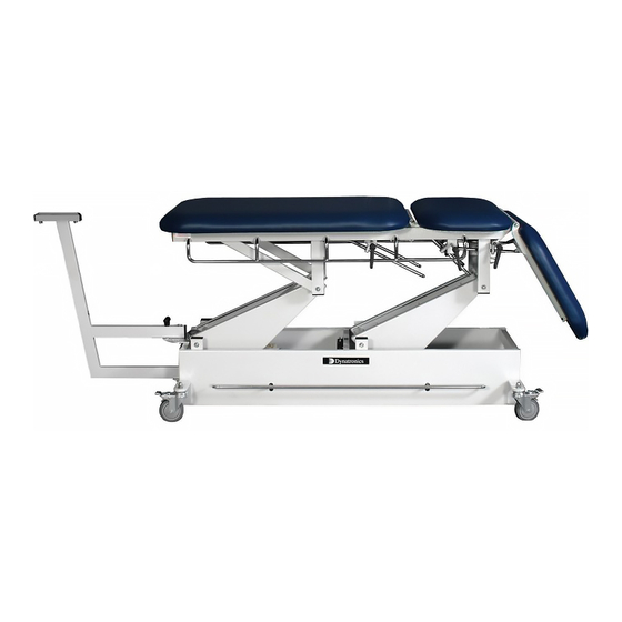
Decompression Table The Dynatron T3 is a qulaity 3-section, Hi-Lo Treatment Table offering maximum features at competitive pricing. The T4 Table features the same framework as the T3 with the added engineering to make it the world’s first combination traction, 3-section table. -
Page 5: Operator's Profile
Traction Treatments. In addition to this information, consult other published sources for additional application and safety instructions. If you have any questions about the operation of this product, contact your Dynatronics’ Dealer/Representative or Dynatronics’ Customer Service at (800) 874-6251. -
Page 6: Installation And Features
Complete the warranty registration form located at the back of this manual and return it to Dynatronics within 30 days of purchase. This is essential to insure you are not billed for services that are covered by the warranty policy. Warranty registration should include all applicable serial numbers. -
Page 7: Assembling Traction Arm
InsTallaTIon and feaTures Assembling Traction Arm The Traction Arm can quickly and easily be assembled by following the steps outlined below. An adjustable wrench is required for assembly. 1. Remove the Nylon Lock Nut (30) from the Traction Arm Pivot Pin (28) attached to the Traction Arm (27). 2. -
Page 8: Attaching Traction Unit
InsTallaTIon and feaTures Attaching Traction Unit Follow the manufactures instructions in order to attach the traction unit to the traction arm. Technical Specifications • Surface dimensions Width 28" wide, Length without Traction arm 81" long Length with Traction arm 105" long (T4) •... -
Page 9: Adjusting The Table Height
InsTallaTIon and feaTures Adjusting the Table Height WARNING Use the electric foot control to Keep hands and feet away from moving mechanisms while adjusting table activate the motor drives that height. Do not change the angle of a section while the patient’s weight is on raise and lower the table. -
Page 10: Warnings And Precautions
WarnIngs and preCauTIons Warnings and Precautions 1. NEVER leave the patient unattended. 2. NEVER place hands or feet near moving mechanisms while raising or lowering the table. 3. When moving the patient onto or off the table, ALWAYS inform the patient of the procedure before beginning. 4. -
Page 11: Technical Information
TeCHnICal InformaTIon Technical Information CAUTION To ensure proper mechanical operation, a daily check and preliminary operation of the table controls is recommended prior to placing a patient on the table. General Specifications Power Requirements: 110-240 V~ Current: 5.0 Amps Frequency: 60 Hz Phase: Single Phase... -
Page 12: Environmental Conditions / Transport And Storage
TeCHnICal InformaTIon Environmental Conditions / Transport and Storage This equipment, while packed for transport or storage, should not be exposed to environmental conditions outside the following ranges: +70°C a. an ambient temperature range of -40°C b. a relative humidity range of 10% to 100% including condensation c. -
Page 13: Symbols And Labels
TeCHnICal InformaTIon Symbols and Labels The following labels are attached to this device. Serial # T4 Serial # T3 Cleaning Naugahyde Surfaces ® The table is upholstered with durable Naugahyde® which may be cleaned according to manufacturer’s directions as listed below. CAUTION Unplug the power cord before cleaning. - Page 14 TeCHnICal InformaTIon Unapproved Cleaning Solutions • Strong Phenols / Phenol Alcohol Combinations • Sodium Hypochlorite / Household Bleach • Sodium Bromide • Citric Acids • Iodophors • Ammonium Chloride • Accelerated Hydrogen Peroxide (0.5%) DYNATRON® T3™ HI-LO TREATMENT TABLE & T4™ TRACTION TABLE | OPERATOR’S MANUAL REV. 10 | 4/4/2018...
-
Page 15: Maintenance And Service
For assistance with any service-related matter or to obtain needed replacement parts, contact Dynatronics’ Customer Service department at 1-800-874-6251. NOTE: Only technically qualified personnel should attempt to service or repair this equipment. -
Page 16: Components And Replacement Parts
ComponenTs and replaCemenT parTs Components and Replacement Parts The following optional accessories and replacement parts are available through your Dynatronics Dealer. Call Dynatronics Customer Service (800) 874-6251 for assistance. No. Part Number Description NHP(color) Nose Hole Plug T4-TOP(color)-A Nose Hole Section... -
Page 17: Replacement Parts Diagrams
replaCemenT parTs dIagrams Replacement Parts Diagrams No. Part Numbers Above Diagram Description NHP(color) Nose Hole Plug T4-TOP(color)-A Nose Hole Section T4-TOP(color)-B Top Mid-Section T4-TOP(color)-C Top Foot-Section DT4PB Pull Bar DTKNOB Lift-back Handle (black) T4SLIDELOCKHANDLE Traction Arm Handle and Sliding Mechanism DP000075 Mobilization Strap Attachment System (Chrome Bar) DP000072... - Page 18 replaCemenT parTs dIagrams Right: T3 Table with Mid-Lift Motor. Both the T3 and T4 Traction Tables are available with the Mid-Lift Motor. Left: T4 Traction Table with standard main Motor No. Motor Part Numbers Description 40-106 Magnetic Motor Max 65 – Main Motor 40-106-A Magnetic Motor Max 63 –...
- Page 19 replaCemenT parTs dIagrams View A enhancement with Mid-Lift Motor. View A enhancement without Mid-Lift Motor. No. Part Numbers View A Description T4-TOP(color)-B Top Mid-Section 40-106-B Magnetic Mid-Lift Motor Max 10 T34MSL Mid-Lift Switch Left 35-005 Mid-Section Gatch Mechanism Spring DP000061 Master Gatch Mechanism Wieldment (controls all three sections) DYNATRON®...
- Page 20 replaCemenT parTs dIagrams View B location of Z-Spring, applicable to both the T3 and the T4 tables. Detail B No. Part Numbers View B Description DP000072 Foot Switch Bar DP000088 Mid-Section Gatch Mechanism Spring T4FOOTSWITCH Foot Switches T34FSC Foot Switch Cable DYNATRON®...
- Page 21 replaCemenT parTs dIagrams Detail D Detail E No. Part Numbers Views D and E Description T4SLIDELOCKHANDLE Traction Arm Handle and Sliding Mechanism DP000084 Slide Rack Block Assembly HW000022 3/16" x 1" Grooved Clevis Pin HW000187 3/16" Push Nut HW000171 12mm (OD) x 4.88mm (ID) x 1mm Thick Washer DP000080 Bent Lock Hinge DP000082...
- Page 22 replaCemenT parTs dIagrams Detail F T4 with Mid-Lift Motor Detail F T3 with Mid-Lift Motor No. Part Numbers Views F Description T34MSL Mid-Lift Switch Left T34MSR Mid-Lift Switch Right HW000017 3/8-16" Nylon Lock Nut DP000106 Gatch Lock Spring (with Mid-Lift Motor only) DYNATRON®...
- Page 23 replaCemenT parTs dIagrams View locations G & H Detail G Detail H No. Part Numbers Views G & H Description DP000006 Traction Arm Assembly (long) DP000099 Traction Arm Pivot Pin HW000071 Nylon Washer (.375 x .875 x .083 ) HW000017 3/8-16"...
-
Page 24: Returning A Unit For Repair
Returning a Unit for Repair Return Authorization If it becomes necessary to return the table or any of its parts for repair, contact Dynatronics’ Customer Service (800) 874-6251. All returns must have a Service Order Number (SVO) or a Return Material Authorization Number (RMA). -
Page 25: Medical Device Reporting Requirements
FDA. In the event of any applicable incident, you should report details of the incident to the Dynatronics Customer Service Department at 1-800-874-6251. Reports should be submitted to the manufacturer immediately to allow the manufacturer to report to the FDA within 2 working days based on the following criteria: If you receive information that reasonably suggests a probability that a device caused or contributed to: a. -
Page 26: Warranty
REGISTRATION REQUIRED: In order for this warranty to be valid, the warranty registration page (included in this operator’s manual) must be filled out and returned to DYNATRONICS within 10 days of the date this product is delivered to the original owner. A copy of an invoice or receipt may be requested to verify purchase date. -
Page 27: Warranty Registration
Dynatronics for instruction. As a trained medical practitioner, you are solely responsible for determining appropriate application of this product for your patients. Before returning this product or any part of this product to Dynatronics for service, you must first obtain a return authorization number. Call 1-800-874-6251.
Need help?
Do you have a question about the Dynatron T3 and is the answer not in the manual?
Questions and answers