
Related Manuals for Notifier NFS2-640/E


Summary of Contents for Notifier NFS2-640/E
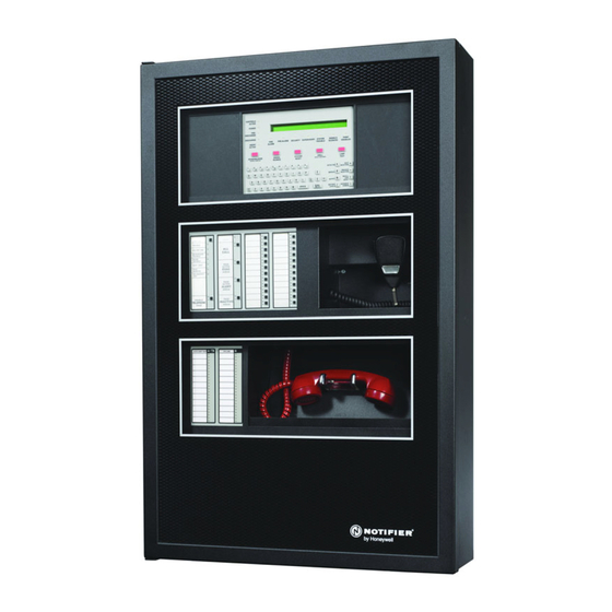
- Page 1 Fire Alarm Control Panel NFS2-640/E Installation Manual Document 52741 7/10/14 Rev: P/N 52741:P2 ECN 13-838...
- Page 2 Adequate written records of all inspections should be kept. (especially in bedrooms), smoking in bed, and violent explosions Limit-D-1-2013 NFS2-640/E Installation Manual — P/N 52741:P2 7/10/14...
- Page 3 HARSH™, NIS™, and NOTI•FIRE•NET™ are all trademarks; and Acclimate® Plus, FlashScan®, NION®, NOTIFIER®, ONYX®, ONYXWorks®, UniNet®, VeriFire®, and VIEW® are all registered trademarks of Honeywell International Inc. Echelon® is a registered trademark and LonWorks™ is a trademark of Echelon Corporation.
- Page 4 • Your suggestion for how to correct/improve documentation Send email messages to: FireSystems.TechPubs@honeywell.com Please note this email address is for documentation feedback only. If you have any technical issues, please contact Technical Services. NFS2-640/E Installation Manual — P/N 52741:P2 7/10/14...
-
Page 5: Table Of Contents
3.5.1: Control Panel Circuit Board & Keypad/Display Unit ...............25 3.5.2: Using NCA-2 as Primary Display .....................26 3.6: Mounting Option Boards ..........................27 3.6.1: Option Boards in the NFS2-640/E Chassis ..................27 3.6.2: Option Boards in CHS-4L .........................28 3.6.3: Option Boards on BMP-1 in Dress Panels ..................29 3.6.4: Transmitter Module TM-4.........................30... - Page 6 Appendix C: Canadian Applications..................74 C.1: Standalone Application ..........................74 C.1.1: NFS2-640/E with KDM-R2 ......................74 C.1.2: NFS2-640/E with NCA-2........................74 C.2: Local Network Application .........................74 C.3: Automatic Alarm Signal Silence.........................74 C.4: Annunciator Applications ...........................74 C.5: Releasing Devices ............................74 NFS2-640/E Installation Manual — P/N 52741:P2 7/10/14...
-
Page 7: Section 1: About This Manual
EIA-485 and EIA-232 Serial Interface Standards • NEC Article 300 Wiring Methods • NEC Article 760 Fire Protective Signaling Systems • Applicable Local and State Building Codes • Requirements of the Local Authority Having Jurisdiction NFS2-640/E Installation Manual — P/N 52741:P2 7/10/14... -
Page 8: Ul 864 Compliance
The following products have not received UL 864 9th Edition certification and may only be used in retrofit applications. Operation of the NFS2-640/E with products not tested for UL 864 9th Edition has not been evaluated and may not comply with NFPA 72 and/or the latest edition of UL 864. - Page 9 51118 FireVoice-25/50, FireVoice-25/50ZS & FireVoice-25/50ZST Manual 52290 FirstCommand Emergency Communication System LS1001-001NF-E RM-1 Series Remote Microphone Installation Document 51138 RA100Z Remote LED Annunciator Installation Document I56-0508 Table 1.1 Reference Documentation (2 of 3) NFS2-640/E Installation Manual — P/N 52741:P2 7/10/14...
-
Page 10: Cautions And Warnings
Information about procedures that could cause programming errors, runtime errors, or equipment damage. WARNING: Indicates information about procedures that could cause irreversible damage to the control panel, irreversible loss of programming data or personal injury. NFS2-640/E Installation Manual — P/N 52741:P2 7/10/14... -
Page 11: Section 2: System Overview
Section 2: System Overview 2.1 System Description The NFS2-640/E control panel is a modular, intelligent fire alarm control panel (FACP) with an extensive list of powerful features. The control panel uses the CPS-24/E integral power supply with battery charger. This is combined with a mounting chassis and cabinet to create a complete fire alarm control system. -
Page 12: 2: Options
NOTE: The CPS-24/E is an integral part of the and is not available separately. One or more chassis. The NFS2-640/E chassis (included with the CPU) mounts the CPU2- 640/CPU2-640E and peripherals. Mount additional rows of equipment in a compatible chassis selected from Table 3.3 on page 24. -
Page 13: 2: Control Panel Circuit Board
2.2.3 Main Power Supply (CPS-24/E) The main power supply is an integral part of the NFS2-640/E and mounts directly over the control panel’s circuit board. It provides a total of 3 A (6 A in alarm) and contains an integral battery charger. -
Page 14: 4: Circuit Board Components
LEDs on the CPU2-640/CPU2-640E and its power supply. Figure 2.2 shows wiring connections; Figure 2.3 shows jumpers, LEDs and switches. See Section 3 “Installation” for larger images and more details. (Larger images are referenced on these drawings.) Figure 2.2 CPU2-640/CPU2-640E and Power-Supply: Wiring Connections NFS2-640/E Installation Manual — P/N 52741:P2 7/10/14... - Page 15 System Components System Overview Figure 2.3 CPU2-640/CPU2-640E and Power-Supply: Jumpers, LEDs and Switches NFS2-640/E Installation Manual — P/N 52741:P2 7/10/14...
-
Page 16: System Cabinets
Table 2.1 Backbox Measurements For details on mounting options within the cabinet, see Section 3.4, “Laying Out Equipment in Cabinet and Chassis”. NFS2-640/E Installation Manual — P/N 52741:P2 7/10/14... -
Page 17: Compatible Equipment
This product has been certified to comply with the requirements in the Standard for Control Units and Accessories for Fire Alarm Systems, UL 864 9th Edition. Operation of the NFS2-640/E with products not tested for UL 864 9th Edition has not been evaluated and may not comply with NFPA 72 and/or the latest edition of UL 864. - Page 18 ABS-4D Annunciator Surface Box MMX-1 Addressable Monitor Module ABS-8RB Annunciator Backbox for ACM-8R MMX-101 Addressable Mini Monitor Module ADP2-640 Dress Panel: NFS2-640/E in lower row MMX-2 Addressable Monitor Module ADP-4B Annunciator Dress Panel N-ELR Assortment ELR Pack with Mounting Plate...
-
Page 19: Section 3: Installation
• Applicable Local and State Building Codes. • Requirements of the Local Authority Having Jurisdiction. • C22.1-98 The Canadian Electrical Code, Part 1. • CAN/ULC-S5524-01 Standard for the Installation of Fire Alarm Systems. NFS2-640/E Installation Manual — P/N 52741:P2 7/10/14... -
Page 20: Installation Checklist
Installation Installation Checklist 3.2 Installation Checklist Table 3.1 provides an installation checklist for installing, wiring, and testing the NFS2-640/E system. It has references to installation information included in manuals listed in Section 1.3 “Related Documents”. Task Refer to Mount the cabinet backbox to the wall. -
Page 21: Laying Out Equipment In Cabinet And Chassis
Figure 3.1 Mounting Holes of a Backbox 3.4 Laying Out Equipment in Cabinet and Chassis The NFS2-640/E allows for flexible system design. Backboxes are available to hold up to four rows of equipment (four chassis), plus batteries. Each chassis has four “slots” -- the basic positions available side by side on a chassis. - Page 22 Refer to the equipment’s documentation for details. Install BP2-4 Battery Plate in front of the battery compartment in NFS2-640/E installations and provides Protected Premises Unit labels. NOTE: The BP2-4 is required for NFS2-640/E installations due to UL’s revised labeling requirements.
- Page 23 Also see Figure 3.3, “Top View of NFS2-640/E Chassis Mounting Figure 3.2 Side View of the NFS2-640/E Chassis Mounting Options NOTE: When designing the cabinet layout, consider separation of power-limited and non-power- limited wiring as discussed in Section 3.11 “UL Power-limited Wiring Requirements”.
- Page 24 • Note: Mount UDACT/UDACT-2 in second or lower row, or in slot 4 of the NFS2-640/E chassis with nothing in front of it. • Note: Mount fiber versions of the NCM and HS-NCM in the top row under knockouts, to avoid excessive bend on the fiber-optic cable.
-
Page 25: Installing The Control Panel
3.5.1 Control Panel Circuit Board & Keypad/Display Unit The control panel comes pre-mounted in the NFS2-640/E chassis, which is usually positioned in the top row of the backbox. The control panel’s CPU occupies three positions at the back of the chassis;... -
Page 26: 2: Using Nca-2 As Primary Display
Secure with six screws and four 1 inch stand-offs as shown in Figure 3.5, “Mounting KDM-R2”. CAUTION: It is critical that all mounting holes of the NFS2-640/E are secured with a screw or standoff to insure continuity of Earth Ground. -
Page 27: Mounting Option Boards
LEM-320’s stacker-connector. 3.6.1 Option Boards in the NFS2-640/E Chassis Mount option boards in slots 3 and 4 of the NFS2-640/E chassis. (See Figure 3.2, Figure 3.6, and Figure 3.7.) For standoff lengths, see Table 3.2. -
Page 28: 2: Option Boards In Chs-4L
Attach the option board using screws provided with the board, or if installing a second option board, with stand-offs provided with the second board. Install stand-offs on these two studs in any one of the four positions on the chassis. Chassis CHS-4L Figure 3.8 Standoff Locations on CHS-4L NFS2-640/E Installation Manual — P/N 52741:P2 7/10/14... -
Page 29: 3: Option Boards On Bmp-1 In Dress Panels
This dress plate is suitable for modules that do not need to be visible or accessible when the door is closed. NFS2-640/E Installation Manual — P/N 52741:P2 7/10/14... -
Page 30: 4: Transmitter Module Tm-4
Figure 3.11 SLC Connections for LEM-320 requirements and specific details. CAUTION: For the SLC to function correctly, the stacker-connector must be installed as shown in Figure 3.12. Do not install other option modules on top of the LEM-320. NFS2-640/E Installation Manual — P/N 52741:P2 7/10/14... -
Page 31: 6: Network Communications Module
See the BMP-1 Product Installation Drawing if considering mounting the module behind blank module plate in a dress plate or annunciator backbox. NOTE: Over-bending fiber-optic cable can damage it. Do not exceed a 3 inch (7.62 cm) minimum bend radius. NFS2-640/E Installation Manual — P/N 52741:P2 7/10/14... -
Page 32: 7: Dvc Digital Voice Command
Refer to the DVC Manual and DVC-RPU Manual. The NFS2-640/E may be directly connected to the DVC for single panel applications. An associated NCA-2 is required when a DAL (digital audio loop) is part of the configuration; this configuration supports NUP-to-NUP-to-NUP configuration for single panel DAL applications. -
Page 33: Connecting The Power Cables
Auxiliary power source – 24 VDC power @ 0.5 A and 5 VDC power @ 0.15 A from TB2 on the CPS-24/E. See Appendix B.1 “Electrical Specifications” for details and overall installation guidelines. NFS2-640/E Installation Manual — P/N 52741:P2 7/10/14... -
Page 34: 2: Connecting The Control Panel To Ac Power
The yellow Trouble indicator may come on for approximately 10 seconds after applying AC power. (This only applies to an unconfigured system.) Each auxiliary power The yellow Trouble indicator comes on because batteries are not connected. supply Table 3.5 AC Power Checklist NFS2-640/E Installation Manual — P/N 52741:P2 7/10/14... -
Page 35: 4: Installing And Connecting The Batteries
Initiating Device Circuit (IDC). The four-wire power circuit energizes the power supervision relay. When you reset the system, the control panel removes power from these terminals for approximately 15 seconds. NFS2-640/E Installation Manual — P/N 52741:P2 7/10/14... -
Page 36: 6: Accessories Dc Power Output Connections
• 5 VDC (nominal) @ 0.15 A max 24V - Blue Wire COM - Black Wire COM - Black Wire 5V - Red Wire Figure 3.17 Connecting to the Accessories Output TB2 on CPS-24/E NFS2-640/E Installation Manual — P/N 52741:P2 7/10/14... -
Page 37: Nac Connections And Releasing Circuits
NOTE: Any NAC can be programmed as a releasing circuit, and the releasing circuit must be supervised; see Figure 4.8–Figure 4.10. For more information, refer to Section 4 “Applications” in this manual and the NFS2-640/E Programming Manual. Refer to the Device Compatibility Document for UL-listed compatible releasing devices. Sample connections for NAC terminals are shown in Figure 3.18. -
Page 38: 1: Stat-X Devices
These are power-limited only if connected to a power-limited source. Using VeriFire Tools, the Supervisory and Security contacts can also be configured as Alarm contacts. Follow instructions in the VeriFire Tools online help. Figure 3.21 Form-C Relay Connections NFS2-640/E Installation Manual — P/N 52741:P2 7/10/14... -
Page 39: Backup-Alarm Switches
So, for example, if SW1 and SW4 were enabled at the time of an alarm during microcontroller failure, NAC#1 and NAC#4 would activate. Follow sequence of steps in Section 3.2 “Installation Checklist”, Table 3.1; this is Step 7. NFS2-640/E Installation Manual — P/N 52741:P2 7/10/14... -
Page 40: Ul Power-Limited Wiring Requirements
NOTE: Drawing is not to scale; proportions and angles are exaggerated to show wire-placement more clearly. NOTE: If additional knockouts are added to the backbox, proper separation of power-limited and nonpower-limited wiring should be maintained. NFS2-640/E Installation Manual — P/N 52741:P2 7/10/14... -
Page 41: 1: Labeling Modules And Circuits
Connector using the wiring specifications shown in the table below. (Custom cable kit P/N 90106 is provided.) Tighten clamp on connector to secure cable. DB-25 Connector TB12 on Control Panel (Custom cable kit 90106) Pin 3 Pin 2 Pin 7 NFS2-640/E Installation Manual — P/N 52741:P2 7/10/14... -
Page 42: 2: Installing And Configuring The Prn Series Printer
Refer to the documentation supplied with the PRN series printer for instructions on using the printer menu controls. Set the printer options (under the menu area) according to the settings listed in Table 3.6. NFS2-640/E Installation Manual — P/N 52741:P2 7/10/14... -
Page 43: 3: Installing And Configuring A Keltron Printer
Set up a Keltron printer as follows: The printer communicates using the following protocol: • Baud Rate: 9600 • Parity: Even • Data bits: 7 Set the printer DIP switches SP1 and SP2 according to settings in Table 3.7. NFS2-640/E Installation Manual — P/N 52741:P2 7/10/14... -
Page 44: 4: Installing And Configuring A Crt-2
Table 3.7 Keltron DIP Switch Settings 3.13.4 Installing and Configuring a CRT-2 A CRT-2 can only be used in a non-networked application when used with the NFS2-640/E. For further details on setting up the CRT-2, refer to the NFS2-640/E Operations Manual. - Page 45 Installing Remote Printers and/or CRT Installation Table 3.8 shows the standard settings for using the CRT-2 with the NFS2-640/E; for one instance where these settings may change slightly see Section 3.13.5 “Connecting Multiple Printers, CRTs, or CRT/PRN Combination”. The basic settings for using the CRT-2 with NFS2-640/E are: •...
-
Page 46: 5: Connecting Multiple Printers, Crts, Or Crt/Prn Combination
) wire is 12,500 feet (3810 meters) total twisted-pair for Style 4, Style 6 and Style 7 circuits. Capacity The NFS2-640/E provides one (1) SLC, with a total capacity of 318 intelligent/addressable devices: • 01-159 intelligent detectors • 01-159 monitor and control modules An optional expander board provides one (1) additional SLC, with the same capacity. -
Page 47: Connecting A Pc For Off-Line Programming
NOTE: Download operations that change the basic program of the control panel must be performed by responsible service personnel in attendance at the control panel. After downloading a program, test the control panel in accordance with NFPA 72. NFS2-640/E Installation Manual — P/N 52741:P2 7/10/14... -
Page 48: Section 4: Applications
(Blank) • Nonreset Ctl • Gen Supervis • Strobe • Release Ckt • Alarms Pend • Gen Trouble • Horn • Rel Ckt Ulc • Gen Alarm • Gen Pend • Trouble Pend NFS2-640/E Installation Manual — P/N 52741:P2 7/10/14... -
Page 49: Nfpa 72 Central Or Remote Station Fire Alarm System (Protected Premises Unit)
NOTE: This application can also be done with the TM-4 Transmitter; refer to the TM-4 Transmitter Module installation document for more details. NOTE: For additional setup information for the UDACT-2, refer to the UDACT-2 Instruction Manual. NFS2-640/E Installation Manual — P/N 52741:P2 7/10/14... - Page 50 Figure 4.2 Typical Wiring Diagram for a Central Station Fire Alarm System NOTE: Install a UL-listed 120 ohm End-of-Line resistor (P/N 71244) UDACT TB1 terminals 3 and 4 if this is the last or only device on EIA-485 line. NFS2-640/E Installation Manual — P/N 52741:P2 7/10/14...
-
Page 51: Central Station Fire Alarm System Canadian Requirements
LED100 A HI B HI LED6 LED7 RCDA RCDB LED4 LED2 STATA STATB LED3 LED5 NCM-W RECON PULSE1 LED1 LED8 RESET POWER TERM Figure 4.3 Central Station Canadian Requirements for Second Dial-Out Connection NFS2-640/E Installation Manual — P/N 52741:P2 7/10/14... -
Page 52: Nfpa 72 Proprietary Fire Alarm Systems
UDACT-2 Manual for compatible receiving units. A simplified drawing of connections between the receiving unit and the NFS2-640/E protected premises unit is shown in Figure 4.4. Connect the receiving unit to the protected premises unit as shown in Section 4.3 “NFPA 72 Central or Remote Station Fire Alarm System (Protected Premises Unit)”. -
Page 53: 2: Installing A Security Tamper Switch
Select the address of the module(s) to be used for security. Select the Type Code SECURITY NOTE: For detailed instruction on programming Type Codes, refer to the NFS2-640/E Programming Manual. NFS2-640/E Installation Manual — P/N 52741:P2 7/10/14... -
Page 54: 5: Wiring For Proprietary Security Alarm Applications
NAC devices used for security cannot be shared with fire NAC devices. • Refer to the Device Compatibility Document for compatible NAC devices. • All monitor modules used for security application must be installed in the NFS2-640/E cabinet with STS-1 Security Tamper Switch. NFS2-640/E Protected Premises Unit UL-listed 47K... -
Page 55: Releasing Applications
Supervised for open circuit and shorts. • Supervised for power loss with power- • Supervised for power loss with power- supervision relay. supervision relay. For more information, refer to the NFS2-640/E Programming Manual. NFS2-640/E Installation Manual — P/N 52741:P2 7/10/14... -
Page 56: 3: Connecting A Releasing Device To The Control Panel
Maintain a 0.25 inch (6.35 mm) spacing between the non-power-limited releasing circuit device wiring and any power-limited circuit wiring.) The releasing circuit must be programmed with a releasing type code listed in the NFS2-640/E Programming Manual. NOTE: As per UL 864 9 Edition, a supervisory signal must be indicated at the panel whenever a releasing circuit is physically disconnected. -
Page 57: 4: Connecting A Releasing Device To The Fcm-1 Module
You can power the module from the power supply of the Control Panel or any UL/ULC listed 24 VDC regulated power-limited power supply for Fire Protective Signaling. For more information, refer to the Device Compatibility Document. NFS2-640/E Installation Manual — P/N 52741:P2 7/10/14... - Page 58 Figure 4.12 Typical Connection of a 24 VDC Releasing Device to the FCM-1 Module Circuit Requirements When connecting a releasing device to the FCM-1 module, note the following: Refer to the Releasing Applications appendix in the NFS2-640/E Programming Manual for configuration details (such as setting the Soak Timer). For applications using power-limited circuits: a) Use an in-line supervisory device (P/N REL-47K) with the FCM-1 module.
-
Page 59: 5: Connecting Releasing Devices To The Fcm-1-Rel Control Module
Only one (1) 24V solenoid or two (2) 12V solenoids in series can be connected to the FCM-1-REL. Do not loop wiring under the screw terminals. Break the wire run to provide supervision of connections. All applications using the FCM-1-REL are power-limited: NFS2-640/E Installation Manual — P/N 52741:P2 7/10/14... -
Page 60: 6: Connecting An Nbg-12Lra Agent Release-Abort Station
Program the releasing circuit for Type Code REL CKT ULC or RELEASE CKT. Circuits are supervised against opens and shorts. Refer to the NFS2-640/E Programming Manual for instructions on setting the Soak Timer. The FCM-1-REL module must be programmed with the correct releasing type code listed in the NFS2-640/E Programming Manual. - Page 61 Releasing Applications Applications NFS2-640/E Installation Manual — P/N 52741:P2 7/10/14...
-
Page 62: Section 5: Testing The System
On systems equipped with a fire fighter’s telephone circuit, make a call from a telephone circuit and confirm a ring tone. Answer the call and confirm communication with the incoming caller. End the call and repeat for each telephone circuit in the system. Continued on next page... NFS2-640/E Installation Manual — P/N 52741:P2 7/10/14... -
Page 63: Battery Checks And Maintenance
Take care to avoid accidental shorting of the leads from uninsulated work benches, tools, bracelets, rings, and coins. WARNING: Shorting the battery leads can damage the battery, equipment, and could cause injury to personnel. NFS2-640/E Installation Manual — P/N 52741:P2 7/10/14... -
Page 64: Appendix A: Power Supply Calculations
4.4 A at 24 VDC during Standby; and • 7.4 A at 24 VDC during Alarm. The current draw from all NACs plus DC output from TB10 and TB2 is 3.0 A during standby and 6.0 A during alarm. NFS2-640/E Installation Manual — P/N 52741:P2 7/10/14... - Page 65 AC power loss.The non-fire alarm current is required to complete the standby battery calculations. After summing all current draws, insert the total in Table A.3. NFS2-640/E Installation Manual — P/N 52741:P2 7/10/14...
-
Page 66: A.2.1: Calculating The Maximum Secondary Power Fire Alarm Current Draw
The result obtained is the amount of current that the batteries must be able to supply to the fire alarm system. Use the result in Table A.4 to determine the size of the batteries needed for the fire alarm system. NFS2-640/E Installation Manual — P/N 52741:P2 7/10/14... - Page 67 † Exclude Amplifiers that are employed for backup. NOTE: The Secondary Fire Alarm Load cannot exceed the following: 12 A with BAT-12260 batteries (12 V, 26 AH). 20 A with BAT-12550 batteries (12 V, 55 AH). NFS2-640/E Installation Manual — P/N 52741:P2 7/10/14...
-
Page 68: A.3: Calculating The Battery Requirements
If the total exceeds 26 AH, the system requires a separate NFS-LBB, BB-100 or BB-200 battery enclosure for two larger capacity batteries. The following battery derating factors must be used for Canadian installations using NFS2-640/E charger: • For a 26 AH battery, use derating factor of 1.5 •... -
Page 69: A.3.2: Calculating The Battery Size
100 AH BAT-121000 BB-100 two for 200 AH BB-200 *Manufactured to our specifications. † Red version available; add “R” to part number listed here Table A.5 Selecting Battery and Battery Backbox NFS2-640/E Installation Manual — P/N 52741:P2 7/10/14... -
Page 70: Appendix B: Electrical Specifications
Note: Refer to Appendix B.2 “Wire Requirements” for limitations. Maximum current 400 mA peak, 200 mA average (max short circuit; circuit will shut down until short is fixed). For battery calculation purposes use 200mA. Maximum resistance 50 ohms (supervised and power-limited) NFS2-640/E Installation Manual — P/N 52741:P2 7/10/14... - Page 71 Control Panel NACs (TB6, TB7, TB8, TB9): 2.2K, 1/2 watt (ELRs) XP6-C, FCM-1 Modules: 47K, 1/2 watt NOTE: For a list of compatible Notification Appliance Circuits and Releasing Circuits see Notifier Device Compatibility Document 15378. Output Relays Output relays for Alarm and Trouble are common on TB4; Supervisory and Security are programmable on TB5.
-
Page 72: B.2: Wire Requirements
NOTE: If running an SLC in conduit with Notification Appliance Circuits, you can reduce problems by exclusively using electronic sounders (such as the SpectrAlert, SpectrAlert Advanced or MA/SS-24 Series) instead of more electronically noisy notification appliances (such as electromechanical bells or horns). NFS2-640/E Installation Manual — P/N 52741:P2 7/10/14... - Page 73 12 AWG (3.31 mm charger * FCM-1 cannot be used for synchronized strobe/sounder applications. Table B.1 Wire Requirements NOTE: Lightning arresters required on circuits extending between buildings; 999 meter length maximum to meet UL 60950. NFS2-640/E Installation Manual — P/N 52741:P2 7/10/14...
-
Page 74: Appendix C: Canadian Applications
Appendix C: Canadian Applications C.1 Standalone Application C.1.1 NFS2-640/E with KDM-R2 If using KDM-R2 as the primary display for NFS2-640/E, an ACS series annunciator must be mounted adjacent to the panel or within NFS2-640/E enclosure. C.1.2 NFS2-640/E with NCA-2 Network Control Annunciator (NCA-2) with 640-character, multi-line display complies with ULC requirements when used as the primary display for NFS2-640/E. - Page 75 Mounting CRT-2 Configuration 44 LEM 31 CRT-2 Function Keys and Parameters 45 Multiple Detector Operation 46 – Installation 41 NACs (Notification Appliance Circuits) DC, also see Power 34 Backup Option 39 DVC 32 NFS2-640/E Installation Manual — P/N 52741:P2 7/10/14...
- Page 76 Protected Premises Unit 49 Wiring Proprietary Security Alarm Applications Related Documentation 8 Relays, see Form-C Relays 38 Wire Requirements 72 Releasing Circuits Connections 37 – Releasing Applications 55 Releasing Applications, Canada 74 Specifications 71 NFS2-640/E Installation Manual — P/N 52741:P2 7/10/14...
- Page 77 Index W–W NFS2-640/E Installation Manual — P/N 52741:P2 7/10/14...
- Page 78 World Headquarters 12 Clintonville Road Northford, CT 06472-1610 USA 203-484-7161 fax 203-484-7118 www.notifier.com...
Need help?
Do you have a question about the NFS2-640/E and is the answer not in the manual?
Questions and answers