
Subscribe to Our Youtube Channel
Related Manuals for Siemens SITRANS RD300


Summary of Contents for Siemens SITRANS RD300
- Page 1 Communications and Displays SITRANS RD300 - Process & Rate/Totalizer Operating Instructions • 08/2017 SITRANS...
- Page 2 The user is responsible for all changes and repairs made to the device by the user or the user’s agent. All new components are to be provided by Siemens Milltronics Process Instruments. Restrict repair to faulty components only.
- Page 3 SITRANS RD300 Table of Contents SITRANS RD300 ------------------------------------------------------------ 1 Benefits ------------------------------------------------------------------------------ 1 SAFETY NOTES ------------------------------------------------------------ 2 The Manual ------------------------------------------------------------------------- 2 SAFETY INFORMATION ------------------------------------------------- 3 INSTALLATION ------------------------------------------------------------- 4 Unpacking --------------------------------------------------------------------------- 4 Panel Mounting Instructions -------------------------------------------------- 4 ...
- Page 4 SIT SITRANS RD300RANS RD300 Program Menu for Single Scale Process --------------------------- 31 Program Menu for Dual-Scale Level Applications ---------------- 31 Multi-Point Calibration & Scaling -------------------------------------- 32 Scaling the Meter (SCALE) ---------------------------------------------- 32 Dual-Scale for Level Application -------------------------------------- 32 ...
- Page 5 SITRANS RD300 Protecting or Locking the Meter ------------------------------------------- 59 Total Reset Password & Non-Resettable Total ----------------------- 59 Making Changes to a Password Protected Meter -------------------- 60 Disabling Password Protection -------------------------------------------- 60 Main Menu (Rate/Total) ------------------------------------------------------- 61 ...
- Page 6 SIT SITRANS RD300RANS RD300 METER OPERATION ----------------------------------------------------- 88 Front Panel Buttons Operation -------------------------------------------- 88 Function Keys Operation ---------------------------------------------------- 88 F4 Operation --------------------------------------------------------------------- 89 Maximum/Minimum Readings ---------------------------------------------- 89 TROUBLESHOOTING ---------------------------------------------------- 90 Diagnostics Menu (diag) ----------------------------------------------------- 90 ...
-
Page 7: Sitrans Rd300
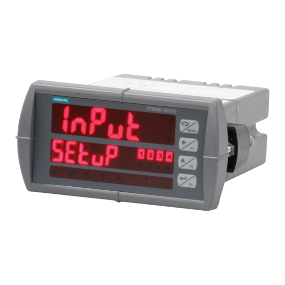
SITRANS RD300 SITRANS RD300 The SITRANS RD300 is a panel mounted digital display for process instrumentation and acts as a multi-purpose, easy to use rate/totalizer ideal for flow rate, total, and control applications. It accepts current and voltage signals (e.g. -
Page 8: Safety Notes
Note: Means important information about the product or that part of the operating manual. The Manual This manual provides instructions for the SITRANS RD300 remote display. The manual is designed to help you get the most out of your Remote Display, and it provides information on the following: ... -
Page 9: Safety Information
CAUTION: Read complete instructions prior to installation and operation of the meter. WARNING: Risk of electric shock or personal injury. WARNING: Hazardous voltages exist within enclosure. Installation and service should be performed only by trained service personnel. A5E31917845 SITRANS RD300 – OPERATING INSTRUCTIONS Page 3... -
Page 10: Installation
3.622" (92 mm) Square Corners to 0.060" (1.5mm) Max Radius 1.772" Panel Cutout (45mm) to DIN 43700 Tolerances: A: +0.032 (+0.8mm) -0.000 (-0.0mm) B: +0.024 (+0.6mm) -0.000 (-0.0mm) 1/8 DIN Panel Cutout and Mounting Page 4 SITRANS RD300 – OPERATING INSTRUCTIONS A5E31917845... -
Page 11: Mounting Dimensions
SITRANS RD300 Mounting Dimensions Meter Dimensions - Side View Meter Dimensions - Top View A5E31917845 SITRANS RD300 – OPERATING INSTRUCTIONS Page 5... -
Page 12: Transmitter Supply Voltage Selection (P+, P-)
Observe all safety regulations. Electrical wiring should be performed in accordance with all applicable national, state, and local codes to prevent damage to the meter and ensure personnel safety. Page 6 SITRANS RD300 – OPERATING INSTRUCTIONS A5E31917845... -
Page 13: Connectors Labeling
The connectors’ label, affixed to the meter, shows the location of all connectors available with requested configuration. WARNING: Do not connect any equipment other than Siemens’s expansion modules, cables, or meters to the RJ45 M-LINK connector. Otherwise damage will occur to the equipment and the meter. -
Page 14: Signal Connections
The display may or may not show a fault condition depending on the nature of the overload. The fuse limits the current to a safe level when it detects a fault condition, and automatically resets itself when the fault condition is removed. Page 8 SITRANS RD300 – OPERATING INSTRUCTIONS A5E31917845... -
Page 15: Modbus Rtu Serial Communications
(NO) and normally closed (NC) contacts of the corresponding relay. The relays’ C terminals should not be confused with the COM (common) terminal of the INPUT SIGNAL connector. RELAY4 RELAY3 RELAY2 RELAY1 Relay Connections A5E31917845 SITRANS RD300 – OPERATING INSTRUCTIONS Page 9... -
Page 16: Switching Inductive Loads
Low Voltage DC Loads Protection Note: Relays are de-rated to 1/14th HP (50 watts) with an inductive load. Page 10 SITRANS RD300 – OPERATING INSTRUCTIONS A5E31917845... -
Page 17: F4 Digital Input Connections
The internal 24 VDC power supply powering the analog output may be used to power other devices, if the analog output is not used. The I+ terminal is the +24 V and the R terminal is the return. A5E31917845 SITRANS RD300 – OPERATING INSTRUCTIONS Page 11... -
Page 18: External Relay & Digital I/O Connections
WARNING: Do not connect or disconnect the expansion modules with the power on! More detailed instructions are provided with each optional expansion module. Expansion Modules & DIN Rail Mounting Kit RLY5 RLY6 RLY7 RLY8 External Relays Module Connections Page 12 SITRANS RD300 – OPERATING INSTRUCTIONS A5E31917845... -
Page 19: Interlock Relay Feature
(safe). The interlock relay front panel LED flashes when locked out. The interlock relay would be wired in-series with the load (N/O contact). See below. Interlock Connection A5E31917845 SITRANS RD300 – OPERATING INSTRUCTIONS Page 13... -
Page 20: Setup And Programming
There are no jumpers to set for the meter input selection. Setup and programming is done through the front panel buttons. After power and input signal connections have been completed and verified, apply power to the meter. Page 14 SITRANS RD300 – OPERATING INSTRUCTIONS A5E31917845... -
Page 21: Meterview Pro Software
“MAINSTAL.” Click “Open folder to view files.” If the computer does not display an AutoPlay dialog for the drive “MAINSTAL,” you should open My Computer and double-click on the drive labeled “MAINSTAL.” A5E31917845 SITRANS RD300 – OPERATING INSTRUCTIONS Page 15... - Page 22 Data logging for one meter at a time is available with MeterView Pro software. More advanced data acquisition may be accomplished by using any Modbus RTU compliant software. Page 16 SITRANS RD300 – OPERATING INSTRUCTIONS A5E31917845...
-
Page 23: Front Panel Buttons And Status Led Indicators
Press the Enter button to access a menu or to accept a setting. Press and hold the Menu button for three seconds to access the advanced features of the meter. A5E31917845 SITRANS RD300 – OPERATING INSTRUCTIONS Page 17... -
Page 24: Display Functions And Messages
Program display 2 value (up to 32 points) Dis 2 Error, calibration not successful, check Error Error signal or programmed value Total time T tb Program total time base base T CF Total Program total conversion factor Page 18 SITRANS RD300 – OPERATING INSTRUCTIONS A5E31917845... - Page 25 Set relay 1 action Auto Automatic Set relay for automatic reset A-nman Auto-manual Set relay for automatic & manual reset any time LatCH Latching Set relay for latching operation (relays assigned to rate) A5E31917845 SITRANS RD300 – OPERATING INSTRUCTIONS Page 19...
- Page 26 Aout Analog output Enter the Analog output scaling menu Dis 1 Display 1 Program display 1 value Out 1 Output 1 Program output 1 value (e.g. 4.000 mA) Page 20 SITRANS RD300 – OPERATING INSTRUCTIONS A5E31917845...
- Page 27 Non-resettable grand total set after nonrst Non-resettable entering “050873” for Gtotal password unloc Unlocked Program password to lock meter locd Locked Enter password to unlock meter 999999 Flashing Overrange condition -99999 display Underrange condition A5E31917845 SITRANS RD300 – OPERATING INSTRUCTIONS Page 21...
-
Page 28: Setting Numeric Values
Press the Enter button, at any time, to accept a setting or Menu button to exit without saving changes. 004. 0 00 00 5. 0 00 004. 0 00 Next Setting dis 1 dis 1 dis 1 Select Increment Accept Next Digital Setting Digit Value Page 22 SITRANS RD300 – OPERATING INSTRUCTIONS A5E31917845... -
Page 29: Configuring The Meter Basic Function
1 & 2 assignment. PV 1 and PV 2 will not appear, as these selections are only used when the meter is configured for dual- scale operation. Enable Totalizer Features Enable Enable Dual-Scale Single PV Features Features A5E31917845 SITRANS RD300 – OPERATING INSTRUCTIONS Page 23... -
Page 30: Configuring As A Single Process Display
It is configured by selecting No (no) for both total (total) and level (level) parameters. Enable Single PV Features Page 24 SITRANS RD300 – OPERATING INSTRUCTIONS A5E31917845... -
Page 31: Configuring As A Rate/Total Meter
It is configured by selecting Yes (yes) for the total (total) parameter. Enable Totalizer Features A5E31917845 SITRANS RD300 – OPERATING INSTRUCTIONS Page 25... -
Page 32: Main Menu (Process)
Enter are not saved. Changes to the settings are saved to memory only after pressing Enter/F3. The display moves to the next menu every time a setting is accepted by pressing Enter/F3. Page 26 SITRANS RD300 – OPERATING INSTRUCTIONS A5E31917845... -
Page 33: Setting Up The Process Meter (Setup)
Relay operation 4-20 mA analog output scaling Press the Enter button to access any menu or press Up arrow button to scroll through choices. Press the Menu button to exit at any time. A5E31917845 SITRANS RD300 – OPERATING INSTRUCTIONS Page 27... -
Page 34: Setting The Process Input Signal (Input)
PV1 & PV2. Enable Totalizer Features Enable Enable Dual-Scale Single PV Features Features Set d-SCAL to no if both displays are to be used for anything other than PV1 & PV2. Page 28 SITRANS RD300 – OPERATING INSTRUCTIONS A5E31917845... -
Page 35: Setting The Input Units Or Custom Tags (Units)
The letters “m” and “w” use two 7-segment LEDs each; when selected the characters to the right are shifted one position. Press and hold up arrow to auto-scroll the characters in the display. A5E31917845 SITRANS RD300 – OPERATING INSTRUCTIONS Page 29... -
Page 36: Setting The Decimal Point (Dec Pt)
Pressing the Up arrow moves the decimal point one place to the left. If the dual-scale level feature is selected, the decimal point selections for PV1 & PV2 are enabled. Page 30 SITRANS RD300 – OPERATING INSTRUCTIONS A5E31917845... -
Page 37: Programming The Meter (Prog)
Program Menu for Single Scale Process Program Menu for Dual-Scale Level Applications Additional parameters, not needed for most applications, are programmed in the Advanced Features menu; see Advanced Features Menu, page 74. A5E31917845 SITRANS RD300 – OPERATING INSTRUCTIONS Page 31... -
Page 38: Multi-Point Calibration & Scaling
The analog input can be displayed in two different scales, by enabling the dual-scale feature (d-SCAL) in the Setup-Input menu, see page 28. To enable the dual-scale feature for some level applications you must select d-SCAL in the Input selection menu. Page 32 SITRANS RD300 – OPERATING INSTRUCTIONS A5E31917845... - Page 39 SITRANS RD300 Scaling the Input for PV1 (SCAL 1) Scaling the Input for PV2 (SCAL 2) A5E31917845 SITRANS RD300 – OPERATING INSTRUCTIONS Page 33...
- Page 40 The minimum input span is the minimum difference between input 1 and input 2 signals required to complete the calibration or scaling of the meter. Input Range Input 1 & Input 2 Span 4-20 mA 0.15 mA 10 VDC 0.01 VDC Page 34 SITRANS RD300 – OPERATING INSTRUCTIONS A5E31917845...
-
Page 41: Calibrating The Meter With External Source (Cal)
The use of a calibrated signal source is strongly recommended to calibrate the meter. The displ a y flashes while sensing the inputs Warm up the meter for at least 15 minutes before performing calibration to ensure specified accuracy. A5E31917845 SITRANS RD300 – OPERATING INSTRUCTIONS Page 35... -
Page 42: Setting The Display Parameter & Intensity (Dsplay)
12. Toggle net/gross Display Intensity: The meter has eight display intensity levels to give the best performance under various lighting conditions. Select intensity 8 for outdoor applications. The default intensity setting is 8. Page 36 SITRANS RD300 – OPERATING INSTRUCTIONS A5E31917845... -
Page 43: Display Setup Menu (Process)
Press the Menu button again and the Up arrow to reach the Program menu and complete the scaling or calibration of the meter. A5E31917845 SITRANS RD300 – OPERATING INSTRUCTIONS Page 37... -
Page 44: Setting The Relay Operation (Relay)
Set point Reset point Fail-safe operation On (enabled) Off (disabled) Time delay On delay (0-999.9 seconds) Off delay (0-999.9 seconds) Relay action for loss (break) of 4-20 mA input (ignore, on, off) Page 38 SITRANS RD300 – OPERATING INSTRUCTIONS A5E31917845... -
Page 45: Setting The Relay Action
Sampling (the relay is activated for a user-specified time) Off (relay state controlled by Interlock feature) The following graphic shows relay 1 action setup; relay 2-8 are set up in a similar fashion. A5E31917845 SITRANS RD300 – OPERATING INSTRUCTIONS Page 39... -
Page 46: Programming Set And Reset Points
Turn Off (Go to non-alarm condition) Ignore (Processed as a low signal condition) Note: This is not a true loop break condition; if the signal drops below 0.005 mA, it is interpreted as a “loop break” condition. Page 40 SITRANS RD300 – OPERATING INSTRUCTIONS A5E31917845... -
Page 47: Relay And Alarm Operation Diagrams
For Manual reset mode, ACK can be pressed anytime to turn "off" relay. To detect a new alarm condition, the signal must go below the set point, and then go above it. A5E31917845 SITRANS RD300 – OPERATING INSTRUCTIONS Page 41... -
Page 48: Low Alarm Operation (Set < Reset)
Manual only after passing above Reset (latching with clear) For Manual reset mode, ACK can be pressed anytime to turn "off" relay. For relay to turn back “on”, signal must go above set point and then go below it. Page 42 SITRANS RD300 – OPERATING INSTRUCTIONS A5E31917845... -
Page 49: High Alarm With Fail-Safe Operation (Set > Reset)
Manual (latching) Relay pressed Manual only after passing below Reset (latching with clear) Note: Relay coil is energized in non-alarm condition. In case of power failure, relay will go to alarm state. A5E31917845 SITRANS RD300 – OPERATING INSTRUCTIONS Page 43... -
Page 50: Low Alarm With Fail-Safe Operation (Set < Reset)
Manual (latching) Relay pressed Manual only after passing above Reset (latching with clear) Note: Relay coil is energized in non-alarm condition. In case of power failure, relay will go to alarm state. Page 44 SITRANS RD300 – OPERATING INSTRUCTIONS A5E31917845... - Page 51 SITRANS RD300 A5E31917845 SITRANS RD300 – OPERATING INSTRUCTIONS Page 45...
-
Page 52: Rate Relay Sampling Operation
When the total reaches the preset, the relay trips and the sample time starts. After the sample time has elapsed, the relay resets. The cycle repeats every time the preset value is added to the total. Page 46 SITRANS RD300 – OPERATING INSTRUCTIONS A5E31917845... -
Page 53: Signal Loss Or Loop Break Relay Operation
When the meter detects a break in the 4-20 mA loop, the relay will go to one of the following selected actions: Turn on (Go to alarm condition) Turn off (Go to non-alarm condition) Ignore (Process as a low signal condition) A5E31917845 SITRANS RD300 – OPERATING INSTRUCTIONS Page 47... -
Page 54: Time Delay Operation
Off time delay. Note: If “Automatic or Manual (A-nmAn)” reset mode is selected, the LED follows the reset point and not the relay state when the relay is acknowledged. Page 48 SITRANS RD300 – OPERATING INSTRUCTIONS A5E31917845... -
Page 55: Relay Operation Details
Closed Open Open Closed alarm state Note: NO = Normally Open, NC = Normally Closed. This refers to the condition of the relay contacts when the power to the meter is off. A5E31917845 SITRANS RD300 – OPERATING INSTRUCTIONS Page 49... -
Page 56: Front Panel Leds
The On and Off terminology does not refer to the status of the relay’s coil, which depends on the fail-safe mode selected. WARNING: In latching relay mode, latched relays will reset (unlatch) when power is cycled. Page 50 SITRANS RD300 – OPERATING INSTRUCTIONS A5E31917845... -
Page 57: Non-Latching Relay (Auto)
In this application, the meter is set up for manual reset at any time. Acknowledging the alarm even if the alarm condition is still present resets the relay and turns off the LED. A5E31917845 SITRANS RD300 – OPERATING INSTRUCTIONS Page 51... -
Page 58: Latching Relay (Lt-Clr)
When the ACK button or the assigned digital input is closed, all relays programmed for manual reset are acknowledged. 7ML19306AD Digital I/O Module DI 1-4 DO 1-4 Acknowledge Relays w/Function Key or Digital Input Page 52 SITRANS RD300 – OPERATING INSTRUCTIONS A5E31917845... -
Page 59: Pump Alternation Control Applications (Altern)
#4 will go into alarm if the level exceeds 40.000. Adding the 4 external relays expansion module allows using the 4 SPDT internal relays for pump alternation and the 4 SPST external relays for high, high-high, low, and low-low alarm indication. A5E31917845 SITRANS RD300 – OPERATING INSTRUCTIONS Page 53... - Page 60 Relay #4 turns the main pump on at 6000 gallons and turns it off at 1000 gallons. With the Pump Alternation feature activated, the next time the level reaches 6000 gallons, relay #3 transfers and starts the backup pump. Page 54 SITRANS RD300 – OPERATING INSTRUCTIONS A5E31917845...
- Page 61 Relay #2 trips the High Level Alarm at 7500 gallons and resets at 6900 gallons. Relay #1 trips the Low Level Alarm at 495 gallons and resets at 750 gallons. A5E31917845 SITRANS RD300 – OPERATING INSTRUCTIONS Page 55...
-
Page 62: Setting Up The Interlock Relay (Force On) Feature
Force On any of the internal relays (1-4). 3. Connect a switch or dry contact between the +5V terminal and the corresponding digital input (dI-1 to dI-4) terminal. DI 1-4 DO 1-4 5 VDC Page 56 SITRANS RD300 – OPERATING INSTRUCTIONS A5E31917845... -
Page 63: Scaling The 4-20 Ma Analog Output (Aout)
The Analog Output menu is used to program the 4-20 mA output based on display values. For instructions on how to program numeric values see Setting Numeric Values, page 22. A5E31917845 SITRANS RD300 – OPERATING INSTRUCTIONS Page 57... -
Page 64: Reset Menu (Reset)
Pass 2: Allows use of function keys, digital inputs and editing set/reset points Pass 3: Restricts all programming, function keys, and digital inputs. If Total is enabled: Total: Prevents resetting the total manually Gtotal: Prevents resetting the grand total manually Page 58 SITRANS RD300 – OPERATING INSTRUCTIONS A5E31917845... -
Page 65: Sitrans Rd300 Protecting Or Locking The Meter
The grand total can be programmed as a non-resettable total by entering the password “050873”. CAUTION: Once the Grand Total has been programmed as “non-resettable” the feature cannot be disabled. A5E31917845 SITRANS RD300 – OPERATING INSTRUCTIONS Page 59... -
Page 66: Making Changes To A Password Protected Meter
Did you forget the password? The password may be disabled by entering a master password once. If you are authorized to make changes, enter the master password 508655 to unlock the meter. Page 60 SITRANS RD300 – OPERATING INSTRUCTIONS A5E31917845... -
Page 67: Main Menu (Rate/Total)
Enter are not saved. Changes to the settings are saved to memory only after pressing Enter/F3. The display moves to the next menu every time a setting is accepted by pressing Enter/F3. A5E31917845 SITRANS RD300 – OPERATING INSTRUCTIONS Page 61... -
Page 68: Setting Up The Rate/Totalizer Meter (Setup)
Relay operation 4-20 mA analog output scaling Press the Enter button to access any menu or press Up arrow button to scroll through choices. Press the Menu button to exit at any time. Page 62 SITRANS RD300 – OPERATING INSTRUCTIONS A5E31917845... -
Page 69: Setting The Rate/Total Input Signal (Input)
Rate/Totalizer. Setting the Decimal Point (dEc pt) The rate, total, and grand total decimal points are independent. See Setting the Decimal Point ( dEc pt ) on page 30 for details. A5E31917845 SITRANS RD300 – OPERATING INSTRUCTIONS Page 63... -
Page 70: Programming The Rate/Totalizer (Prog)
The process input may be calibrated or scaled to any display value within the range of the meter. Additional parameters, not needed for most applications, are programmed in the Advanced Features menu; see Advanced Features Menu , page 74. Page 64 SITRANS RD300 – OPERATING INSTRUCTIONS A5E31917845... -
Page 71: Input Calibration Method (Incal)
32 points (default is 2). The number of points should be set in Scale and Calibrate accordingly under the Number of Points ( nopts ) menu selection prior to scaling and calibration of the meter, see page 80 for details. A5E31917845 SITRANS RD300 – OPERATING INSTRUCTIONS Page 65... -
Page 72: Scaling The Meter (Scale)
Input signal is not connected to the proper terminals or it is connected backwards. Wrong signal selection in Setup menu. Minimum input span requirements not maintained. Input 1 signal inadvertently applied to calibrate input 2. Page 66 SITRANS RD300 – OPERATING INSTRUCTIONS A5E31917845... -
Page 73: Calibrating The Meter With External Source (Cal)
The use of a calibrated signal source is strongly recommended to calibrate the meter. T he display flashes while sensing the inputs Warm up the meter for at least 15 minutes before performing calibration to ensure specified accuracy. A5E31917845 SITRANS RD300 – OPERATING INSTRUCTIONS Page 67... -
Page 74: Time Base, Total Conversion Factor & Total Reset
Non-Resettable Totalizer The total and grand total can be password-protected to prevent unauthorized resets. The grand total can be programmed as a non- resettable total, see page 59 for details. Page 68 SITRANS RD300 – OPERATING INSTRUCTIONS A5E31917845... -
Page 75: Setting The Display Parameter & Intensity (Dsplay)
For example, if the upper display is set to total , selecting d unit to display on the lower display will have the total appear on the upper display, and the total unit appear on the lower display. A5E31917845 SITRANS RD300 – OPERATING INSTRUCTIONS Page 69... -
Page 76: Display Setup Menu (Rate/Total)
Press the Menu button again and the Up arrow to reach the Program menu and complete the scaling or calibration of the meter. Page 70 SITRANS RD300 – OPERATING INSTRUCTIONS A5E31917845... -
Page 77: Setting The Relay Operation For Rate/Total (Relay)
Set and reset points Fail-safe operation On (enabled) Off (disabled) Time delay On delay (0-999.9 seconds) Off delay (0-999.9 seconds) Relay action for loss (break) of 4-20 mA input (ignore, on, off) A5E31917845 SITRANS RD300 – OPERATING INSTRUCTIONS Page 71... -
Page 78: Relay Assignment (Assign)
Relay Assignment (Assign) The relays can be assigned to any of the following parameters: Rate for low or high alarm indication Total for alarm indication Grand total for alarm indication Modbus input process variable Page 72 SITRANS RD300 – OPERATING INSTRUCTIONS A5E31917845... -
Page 79: Setting The Relay Action
Control Menu (Contrl) See Control Menu ( Contrl ) on page 58 for details. Setting Up the Password (pass) See Setting Up the Password ( pass ) on page 58 for details. A5E31917845 SITRANS RD300 – OPERATING INSTRUCTIONS Page 73... -
Page 80: Advanced Features Menu
To simplify the setup process, functions not needed for most applications are located in the Advanced Features menu. Press and hold the Menu button for three seconds to access the advanced features of the meter. Page 74 SITRANS RD300 – OPERATING INSTRUCTIONS A5E31917845... -
Page 81: Advanced Features Menu & Display Messages
Set start for total or grand total countdown C Strt AoutPr Analog output Program analog output parameters programming Source Source Select source for the 4-20 mA output Overrange Program mA output for display overrange O-rang A5E31917845 SITRANS RD300 – OPERATING INSTRUCTIONS Page 75... - Page 82 Calibrate high voltage input (e.g. 10 V) Diagnostics Display parameter settings Diag LED test Test all LEDs LED t Info Information Display software and S/N information Erase Erase Erase MeterView Pro software stored in meter’s memory Page 76 SITRANS RD300 – OPERATING INSTRUCTIONS A5E31917845...
-
Page 83: Noise Filter (Filter)
Rounding causes the display to round to the nearest value according the rounding selected. See examples below: Rounding Actual Display Actual Display Selection Value Value Value Value 12.022 12.022 12.023 12.023 12.022 12.020 12.023 12.025 12.024 12.020 12.025 12.030 A5E31917845 SITRANS RD300 – OPERATING INSTRUCTIONS Page 77... -
Page 84: Modbus Rtu Serial Communications (Serial)
Note: More detailed instructions are provided with each optional serial communications adapter. Note: Refer to the SITRANS RD300 Modbus Register Tables located at www.siemens.com for details. When using more than one meter in a multi-drop mode, each meter must be provided with its own unique address. -
Page 85: Select Menu (Select)
Meters are set up at the factory for linear function with 2-point linearization. The linear function provides a display that is linear with respect to the input signal. A5E31917845 SITRANS RD300 – OPERATING INSTRUCTIONS Page 79... - Page 86 Programmable Exponent Linearization (Prog E) The programmable exponent can be used to linearize the signal from level transmitters in open-channel flow applications using weirs and flumes. Page 80 SITRANS RD300 – OPERATING INSTRUCTIONS A5E31917845...
- Page 87 4. Press Enter and change the display 2 value to 3558.4. 5. The meter is now displaying the volume in liters. Note: The display can be scaled to display the volume in any engineering units. A5E31917845 SITRANS RD300 – OPERATING INSTRUCTIONS Page 81...
-
Page 88: Low-Flow Cutoff (Cutoff)
Max: Maximum analog output value allowed regardless of input Min: Minimum analog output value allowed regardless of input Calibrate: Calibrate the internal 4-20 mA source reference used to scale the 4-20 mA output Page 82 SITRANS RD300 – OPERATING INSTRUCTIONS A5E31917845... -
Page 89: Analog Output Calibration
0.1 µA to measure the output current. The values saved internally during this procedure are used for scaling the 4-20 mA output in the Setup menu. A5E31917845 SITRANS RD300 – OPERATING INSTRUCTIONS Page 83... -
Page 90: Programmable Function Keys User Menu (User)
Min on display line 2 Enter button/F3 Ln2 Lo Enter Max/min display line 2 Alarm 1 – 8 Ln2 HL Alm 1 Force relay 1-4 on Grand total on line 2 F On 1 Ln2 gt Page 84 SITRANS RD300 – OPERATING INSTRUCTIONS A5E31917845... -
Page 91: Internal Source Calibration (Ical)
Set the display value to correspond to the input signal being calibrated, typically 4.000 mA. The display moves to the high input calibration ( C Hi ). Apply the high input signal and press Enter. A5E31917845 SITRANS RD300 – OPERATING INSTRUCTIONS Page 85... - Page 92 Low and high input signals can be any valid values within the range of the meter. Observe minimum input span requirements between input 1 and input 2. Low input should be less than high input signal. Page 86 SITRANS RD300 – OPERATING INSTRUCTIONS A5E31917845...
- Page 93 The minimum input span is the minimum difference between input 1 and input 2 signals required to complete the calibration or scaling of the meter. Input Range Input 1 & Input 2 Span 4-20 mA 0.15 mA 10 VDC 0.01 VDC A5E31917845 SITRANS RD300 – OPERATING INSTRUCTIONS Page 87...
-
Page 94: Front Panel Buttons Operation
During operation, the programmable function keys operate according to the way they have been programmed in the Advanced Features – User menu. The table above shows the factory default settings for F1, F2, and F3. Page 88 SITRANS RD300 – OPERATING INSTRUCTIONS A5E31917845... -
Page 95: F4 Operation
To display max/min readings continuously: Assign either display to Max ( d Hi ), Min ( d Lo ), or toggle between Max and Min ( d HL ) every 10 seconds. A5E31917845 SITRANS RD300 – OPERATING INSTRUCTIONS Page 89... -
Page 96: Troubleshooting
( UER ) information. Write down the information as it is displayed. Continue pressing Enter until all the information is displayed. The meter returns to Run Mode after displaying all the settings. Page 90 SITRANS RD300 – OPERATING INSTRUCTIONS A5E31917845... -
Page 97: Reset Meter To Factory Defaults
Note: If Enter is not pressed within three seconds, the display returns to the Diagnostics menu. The meter goes through an initialization sequence (similar as on power-up), and loads the factory default settings. A5E31917845 SITRANS RD300 – OPERATING INSTRUCTIONS Page 91... -
Page 98: Factory Defaults & User Settings
Decimal point 3 places ddd. d dd Cutoff value 0.000 (disabled) CutofF Upper display Rate/Process Line 1 Lower display Total value Line 2 Display intensity d-Inty Total time base Second T tb Page 92 SITRANS RD300 – OPERATING INSTRUCTIONS A5E31917845... - Page 99 Relay 3 action Automatic Act 3 Relay 3 set point 3.000 Set 3 Relay 3 reset point 2.500 RSt 3 Relay 4 action Automatic Act 4 Relay 4 set point 4.000 Set 4 A5E31917845 SITRANS RD300 – OPERATING INSTRUCTIONS Page 93...
- Page 100 Reset max & min Password 1 000000 (unlocked) Pass 1 Password 2 000000 (unlocked) Pass 2 Password 3 000000 (unlocked) Pass 3 Total password 000000 (unlocked) Total Grand total password 000000 (unlocked) Gtotal Page 94 SITRANS RD300 – OPERATING INSTRUCTIONS A5E31917845...
-
Page 101: Specifications
Total: Prevents resetting the total manually Gtotal: Prevents resetting the grand total manually NON-VOLATILE All programmed settings are stored in non-volatile memory MEMORY for a minimum of ten years if power is lost. A5E31917845 SITRANS RD300 – OPERATING INSTRUCTIONS Page 95... - Page 102 TORQUE OVERALL 4.68" x 2.45" x 5.64" (119 mm x 62 mm x 143 mm) DIMENSIONS (W x H x D) WEIGHT 9.5 oz (269 g) WARRANTY 3 years parts & labor Page 96 SITRANS RD300 – OPERATING INSTRUCTIONS A5E31917845...
-
Page 103: Process Input
F4 DIGITAL INPUT 3.3 VDC on contact. Connect normally open contacts CONTACTS across F4 to COM. F4 DIGITAL INPUT Logic High: 3 to 5 VDC LOGIC LEVELS Logic Low: 0 to 1.25 VDC A5E31917845 SITRANS RD300 – OPERATING INSTRUCTIONS Page 97... -
Page 104: Rate/Totalizer
NON-RESETTABLE The grand total can be programmed as a non-resettable TOTAL total by entering the password “050873”. CAUTION: Once the Grand Total has been programmed as “non-resettable” the feature cannot be disabled. Page 98 SITRANS RD300 – OPERATING INSTRUCTIONS A5E31917845... -
Page 105: Relays
Note: Relay coil is energized in non-alarm condition. In case of power failure, relay will go to alarm state. AUTO When power is applied to the meter, relays will reflect the INITIALIZATION state of the input to the meter. A5E31917845 SITRANS RD300 – OPERATING INSTRUCTIONS Page 99... -
Page 106: Isolated 4-20 Ma Transmitter Output
Even, Odd, or None with 1 or 2 stop bits BYTE-TO-BYTE 0.01 – 2.54 second TIMEOUT TURN AROUND Less than 2 ms (fixed) DELAY Note: Refer to the SITRANS RD300 Modbus Register Tables located at www.siemens.com for details. Page 100 SITRANS RD300 – OPERATING INSTRUCTIONS A5E31917845... -
Page 107: Meterview Pro Software
UL 508 Industrial Control Equipment UL FILE NUMBER E311750 FRONT PANEL UL Type 4X, NEMA 4X, IP65; panel gasket provided LOW VOLTAGE EN 61010-1:2010 DIRECTIVE Safety requirements for measurement, control, and laboratory use A5E31917845 SITRANS RD300 – OPERATING INSTRUCTIONS Page 101... -
Page 108: Electromagnetic Compatibility
Testing was conducted on RD300 meters installed through the covers of grounded metal enclosures with cable shields grounded at the point of entry representing installations designed to optimize EMC performance. Declaration of Conformity available at www.siemens.com Page 102 SITRANS RD300 – OPERATING INSTRUCTIONS A5E31917845... -
Page 109: Troubleshooting Tips
Note: Certain sequences of events can cause unexpected results. To solve these issues, it is best to start fresh from factory defaults and map changes ahead of time, rather than at random. A5E31917845 SITRANS RD300 – OPERATING INSTRUCTIONS Page 103... - Page 110 Siemens AG Subject to change without prior notice Industry Sector A5E31917845 Rev. AE 1954 Technology Drive *A5E31917845* P.O. Box 4225 © Siemens AG 2017 Peterborough, ON Canada K9J7B1 Printed in Canada email: techpubs.smpi@siemens.com LIM6200SI_E www.siemens.com/processautomation SFT039 Ver 4.000 & up...
Need help?
Do you have a question about the SITRANS RD300 and is the answer not in the manual?
Questions and answers