Table of Contents
Advertisement
Quick Links
SITRANS F
Coriolis flowmeters
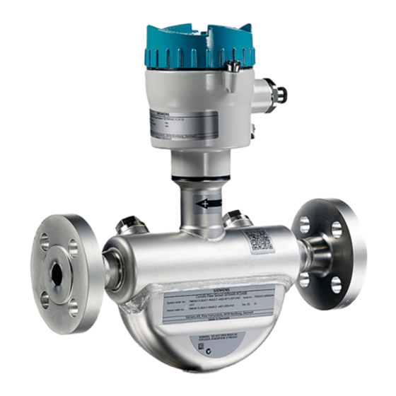
SITRANS FC410
Compact Operating Instructions
7ME461 (Standard sensor)
7ME462 (Hygienic)
7ME471 (NAMUR)
05/2020
A5E39942309-AB
Introduction
Safety notes
Installing/mounting
Connecting
Commissioning
Service and maintenance
Technical data
Product documentation and
support
1
2
3
4
5
6
7
A
Advertisement
Table of Contents

Related Manuals for Siemens SITRANS F SITRANS FC410


Summary of Contents for Siemens SITRANS F SITRANS FC410
- Page 1 Introduction Safety notes Installing/mounting SITRANS F Connecting Coriolis flowmeters SITRANS FC410 Commissioning Service and maintenance Compact Operating Instructions Technical data Product documentation and support 7ME461 (Standard sensor) 7ME462 (Hygienic) 7ME471 (NAMUR) 05/2020 A5E39942309-AB...
- Page 2 Note the following: WARNING Siemens products may only be used for the applications described in the catalog and in the relevant technical documentation. If products and components from other manufacturers are used, these must be recommended or approved by Siemens. Proper transport, storage, installation, assembly, commissioning, operation and maintenance are required to ensure that the products operate safely and without any problems.
-
Page 3: Table Of Contents
Table of contents Introduction..............................5 Document history ........................5 Designated use ........................10 Product compatibility ......................10 Checking the consignment.....................10 Security information .......................11 Transportation and storage ....................12 Safety notes..............................13 Preconditions for safe use......................13 2.1.1 Conformity with European directives..................14 Requirements for special applications ...................14 Use in hazardous areas ......................15 2.3.1 Special conditions for safe use ....................15 Installing/mounting............................17... - Page 4 Table of contents Return procedure ........................39 Disposal ..........................40 6.7.1 Special disposal required .......................40 Technical data ............................41 Power .............................41 Modbus Communication Specification ...................41 Operating conditions ......................42 Certificates and approvals......................43 Product documentation and support......................45 Product documentation ......................45 Technical support........................46 Index................................47 SITRANS FC410 Compact Operating Instructions, 05/2020, A5E39942309-AB...
-
Page 5: Introduction
Introduction These instructions contain all information required to commission and use the device. Read the instructions carefully prior to installation and commissioning. In order to use the device correctly, first review its principle of operation. The instructions are aimed at persons mechanically installing the device, connecting it electronically, configuring the parameters and commissioning it, as well as service and maintenance engineers. - Page 6 Introduction 1.1 Document history FC410: Nameplate with general information SIEMENS ① SITRANS FC410 Product name ② Firmware version ③ Hardware version ④ Manufacturer Manufacturer name and location ⑤ Country Manufacturing country ⑥ Address range Modbus device address range ⑦ Communication Communication: Modbus Master/Slave RTU technology ⑧...
- Page 7 The flowmeter serial number is constructed as follows: PPYMDDxxxxxx where PP = Production factory (Siemens S.A.S. Haguenau: N1) Y = Production year (for encryption, see below) M = Production month (for encryption, see below) DD = Production day (for encryption, see below)
- Page 8 Introduction 1.1 Document history November December Day (DD) Code Day 1 to 31 01 to 31 (corresponding to the actual date) FCS400 sensor: Nameplate with specific information ① EX approvals Ex approval specifications Group II 1/2: category 1/2 (On Zone 0) for gas for use in explosive atmosphere...
- Page 9 Introduction 1.1 Document history Note Approval identifications Approval certificates and notified body identifications are available for download at siemens.com FCS400 sensor: Nameplate with approval information ① QR code Product-specific QR code ② C✓ C-tick logo ③ WEEE symbol, see Disposal (Page 40)
-
Page 10: Designated Use
Introduction 1.4 Checking the consignment QR code With the use of a smart phone, the QR code provides a direct link to ● the product support portal, which includes access to the "How to Install" YouTube video ● the product and production-specific documentation maintained in the production database. Designated use Use the device in accordance with the information on the nameplate and in the Technical data (Page 41). -
Page 11: Security Information
Siemens’ products and solutions undergo continuous development to make them more secure. Siemens strongly recommends that product updates are applied as soon as they are available and that the latest product versions are used. Use of product versions that are no longer supported, and failure to apply the latest updates may increase customer’s exposure to cyber... -
Page 12: Transportation And Storage
The content reflects the technical status at the time of publishing. Siemens reserves the right to make technical changes in the course of further development. -
Page 13: Safety Notes
Safety notes Preconditions for safe use This device left the factory in good working condition. In order to maintain this status and to ensure safe operation of the device, observe these instructions and all the specifications relevant to safety. Observe the information and symbols on the device. Do not remove any information or symbols from the device. -
Page 14: Conformity With European Directives
If you need additional information not covered by these instructions, contact your local Siemens office or company representative. Note Operation under special ambient conditions... -
Page 15: Use In Hazardous Areas
Further information and instructions including approval-specific special conditions for safe use in Ex applications can be found in the certificates on the documentation disk and at the product web page (www.siemens.com/FC410). WARNING Substitution of components Substitution of components may impair Intrinsic Safety. - Page 16 Safety notes 2.3 Use in hazardous areas Qualified personnel for hazardous area applications Persons who install, connect, commission, operate, and service the device in a hazardous area must have the following specific qualifications: ● They are authorized, trained or instructed in operating and maintaining devices and systems according to the safety regulations for electrical circuits, high pressures, aggressive, and hazardous media.
-
Page 17: Installing/Mounting
Refer to the information in Technical data (Page 41). Note Material compatibility Siemens can provide you with support concerning selection of sensor components wetted by process media. However, you are responsible for the selection of components. Siemens accepts no liability for faults or failures resulting from incompatible materials. - Page 18 Installing/mounting 3.1 Basic safety notes WARNING Exceeded maximum permissible operating pressure Risk of injury or poisoning. The maximum permissible operating pressure depends on the device version, pressure limit and temperature rating. The device can be damaged if the operating pressure is exceeded. Hot, toxic and corrosive process media could be released.
-
Page 19: Installation Location Requirements
Installing/mounting 3.1 Basic safety notes 3.1.2 Installation location requirements CAUTION Strong vibrations Damage to device ● In plants with strong vibrations, mount the transmitter in a low vibration environment away from the sensor. NOTICE Aggressive atmospheres Damage to device through penetration of aggressive vapors. ●... -
Page 20: Proper Mounting
Installing/mounting 3.2 Sensor installation 3.1.3 Proper mounting NOTICE Incorrect mounting The device can be damaged, destroyed, or its functionality impaired through improper mounting. ● Before installing ensure there is no visible damage to the device. ● Make sure that process connectors are clean, and suitable gaskets and glands are used. ●... - Page 21 Installing/mounting 3.2 Sensor installation Location in the system The optimum location in the system depends on the application: ● Liquid applications Gas or vapor bubbles in the fluid may result in erroneous measurements, particularly in the density measurement. – Do not install the flowmeter at the highest point in the system, where bubbles will be trapped.
- Page 22 Orienting the sensor The sensor operates in any orientation. The optimal orientation depends on the process fluid and the process conditions. Siemens recommends orienting the sensor in one of the following ways: 1. Vertical installation with an upwards flow (self-draining)
-
Page 23: Disassembly
Installing/mounting 3.3 Disassembly Installation in a drop line is only recommended if a pipeline reduction or orifice with a smaller cross-section can be installed to create back-pressure and prevent the sensor from being partially drained while measuring. ① Back pressure orifice ②... - Page 24 Installing/mounting 3.3 Disassembly SITRANS FC410 Compact Operating Instructions, 05/2020, A5E39942309-AB...
-
Page 25: Connecting
Connecting Basic safety notes WARNING Unsuitable cables, cable glands and/or plugs Risk of explosion in hazardous areas. ● Use only cable glands/plugs that comply with the requirements for the relevant type of protection. ● Tighten the cable glands in accordance with the torques specified in Technical data (Page 41). - Page 26 Connecting 4.1 Basic safety notes WARNING Improper power supply Risk of explosion in hazardous areas as result of incorrect power supply. ● Connect the device in accordance with the specified power supply and signal circuits. The relevant specifications can be found in the certificates, in Technical data (Page 41) or on the nameplate.
-
Page 27: Connecting The Fc410
It is recommended to use cables supplied by Siemens. ● Siemens supplied cables can be ordered with M12 plug on both ends or without plug. ● To guarantee the IP67 degree of protection, ensure that both ends of the cables are given equivalent protection from ingress of moisture. - Page 28 Connecting 4.2 Connecting the FC410 WARNING Cable requirements Cables must be suitable for the temperature (at least 70 °C) and be flammability-rated to at least V-2. Note End Of Line (EOL) termination The FCT010 EOL termination DIP switch is default set to EOL active. To change termination setting see Warnings (Page 27).
- Page 29 Connecting 4.2 Connecting the FC410 DIP switch settings for communication set-up DIP switch Com‐ Switch 1 Switch 2 Switch 3 Switch 4 munication set-up EOL active EOL not active NOTICE Avoid DIP switch settings not mentioned in the table DIP switch settings not mentioned in the table preceding are not allowed and may reduce communication interface reliability.
- Page 30 Connecting 4.2 Connecting the FC410 8. Connect the wires to the terminals according to the list below. Terminal number Description Wire color (Siemens cable) 15 V Orange Yellow RS-485 / B White RS-485 / A Blue Figure 4-2 Sensor terminal compartment 9.
- Page 31 Connecting 4.2 Connecting the FC410 12.Assemble and tighten the cable gland. 13.Remove the O-ring from lid. 14.Reinstate the lid and screw in until the mechanical stop. Wind back the lid by one turn. 15.Mount the O-ring by pulling it over the lid and tighten the lid until you feel friction from the O- ring on both sides.
- Page 32 Connecting 4.2 Connecting the FC410 SITRANS FC410 Compact Operating Instructions, 05/2020, A5E39942309-AB...
-
Page 33: Commissioning
Commissioning Basic safety notes WARNING Improper commissioning in hazardous areas Device failure or risk of explosion in hazardous areas. ● Do not commission the device until it has been mounted completely and connected in accordance with the information in Installing/mounting (Page 17). ●... - Page 34 Commissioning 5.1 Basic safety notes WARNING Opening device in energized state Risk of explosion in hazardous areas ● Only open the device in a de-energized state. ● Check prior to commissioning that the cover, cover locks, and cable inlets are assembled in accordance with the directives.
-
Page 35: Service And Maintenance
● Reliability of power supply, lightning protection, and grounds WARNING Impermissible repair of explosion protected devices Risk of explosion in hazardous areas ● Repair must be carried out by Siemens authorized personnel only. WARNING Dust layers above 5 mm Risk of explosion in hazardous areas. -
Page 36: Cleaning
Service and maintenance 6.2 Cleaning WARNING Leaks in the sample gas path Risk of poisoning. When measuring toxic process media, these can be released or collect in the device if there are leaks in the sample gas path. ● Purge the device as described in Commissioning (Page 33). ●... -
Page 37: Maintenance And Repair Work
WARNING Impermissible repair of explosion protected devices Risk of explosion in hazardous areas ● Repair must be carried out by Siemens authorized personnel only. WARNING Maintenance during continued operation in a hazardous area There is a risk of explosion when carrying out repairs and maintenance on the device in a hazardous area. -
Page 38: Replacing The Device
Service and maintenance 6.4 Replacing the device WARNING Hot, toxic or corrosive process media Risk of injury during maintenance work. When working on the process connection, hot, toxic or corrosive process media could be released. ● As long as the device is under pressure, do not loosen process connections and do not remove any parts that are pressurized. -
Page 39: Transportation And Storage
● Devices/replacement parts should be returned in their original packaging. ● If the original packaging is no longer available, ensure that all shipments are properly packaged to provide sufficient protection during transport. Siemens cannot assume liability for any costs associated with transportation damages. -
Page 40: Disposal
Observe the specific regulations valid in your country. Further information about devices containing batteries can be found at: Information about battery / product return (WEEE) (https:// support.industry.siemens.com/cs/document/109479891/) SITRANS FC410 Compact Operating Instructions, 05/2020, A5E39942309-AB... -
Page 41: Technical Data
Technical data Power Table 7-1 Power supply Description Specification Supply voltage [V] 12 - 27 VDC Um: 60 VDC for Ex d, t 12 - 24 VDC Reverse polarity protection Power consumption 1.1 W Specification in case of Intrinsic safety power supply: Ui: 20 V, Ii: 484 mA, Pi: 2.3 W, Li: 0.6 uH, Ci: 1.9 nF. -
Page 42: Operating Conditions
Technical data 7.3 Operating conditions Description Specification Connector type M12 or cable termination Supported function codes ● 3: read holding registers ● 16: write multiple registers ● 8: diagnostics Broadcast Maximum cable length [m] 600 meters (@ 115 200 bits/sec) Standard Modbus over serial line v 1.0 Certification... -
Page 43: Certificates And Approvals
Process media density (min to max) [kg/m (lb/ft 1 to 5000 (0.06 to 312) Process media gauge max pressure [bar (psi)] 160 (2321) Hastelloy 100 (1450) st. steel Pressure drop See Siemens Sizing & Calculation tool (https://pia- portal.automation.siemens.com/SIE/ Z3_PIA_PORTAL/ ~flNUQVRFPTIwNDg5LjAwMi4wMS4 wMQ==?~okcode=EV_CAL) Pressure temperature ratings... - Page 44 Technical data 7.4 Certificates and approvals SITRANS FC410 flowmeter cCSAus (Kanada, USA) Ex db ia IIC T6-T3 Gb 2508644 Ex tb IIIC T135°C Db Ex ia IIIC T135°C Da Class I, II, III, Division 1, Groups A, B, C, D, E, F, G Class I, Zone 1, AEx db ia IIC T6-T3 Gb Zone 21, AEx tb IIIC T135°C Db Zone 20, AEx ia IIIC T135°C Da...
-
Page 45: Product Documentation And Support
– "Download as html5, only PC": Open or save the manual in the HTML5 view on your PC You can also find manuals with the Mobile app at Industry Online Support (https:// support.industry.siemens.com/cs/ww/en/sc/2067). Download the app to your mobile device and scan the device QR code. Product documentation by serial number Using the PIA Life Cycle Portal, you can access the serial number-specific product information including technical specifications, spare parts, calibration data, or factory certificates. -
Page 46: Technical Support
In addition to our technical support, Siemens offers comprehensive online services at Service & Support (http://www.siemens.com/automation/serviceandsupport). Contact If you have further questions about the device, contact your local Siemens representative at Personal Contact (http://www.automation.siemens.com/partner). To find the contact for your product, go to "all products and branches" and select "Products &... -
Page 47: Index
Index Hotline, (Refer to Support request) Approval information nameplate Sensor, 9 Installation Gas, 21 Inlet / Outlet conditions, 20 Liquid, 21 Location in the system, 20 Cable requirements, 27 Orienting the sensor, 22 Catalog Upstream / Downstream, 20 catalog sheets, 45 Certificates, 13, 45 Certificates and approvals, 43, 44 Cleaning, 36... - Page 48 Index Return procedure, 39 Scope of delivery, 11 Sensor orientation, (See Installation) Service, 46 Service and support Internet, 46 Specific information nameplate Sensor, 8 Support, 46 Support request, 46 Symbols, (Refer to warning symbols) Technical support, 46 partner, 46 personal contact, 46 Termination DIP switches, 28 Test certificates, 13 Warning symbols, 13...
Need help?
Do you have a question about the SITRANS F SITRANS FC410 and is the answer not in the manual?
Questions and answers