Siemens SITRANS F M MAG 5000 Manual
Hide thumbs
Also See for SITRANS F M MAG 5000:
- Operating instructions manual (106 pages) ,
- Instructions manual (12 pages) ,
- Instructions (4 pages)

Related Manuals for Siemens SITRANS F M MAG 5000


Summary of Contents for Siemens SITRANS F M MAG 5000
- Page 1 SITRANS F M MAG 5000/6000 Manual info@eltra-trade.com +421 552 601 099 www.eltra-trade.com...
- Page 2 MAG 5000 is a series of transmitters from Siemens with a micropro- cessor, which is designed to work in electromagnetic flowmeters. MAGFLO 5000 electronic converters have the following features: - SENSORPROM technology - Graphic display available - Dosage function - Error log...
- Page 3 Transmitter collects all the data from the measuring sensors and also supplies some system elements. The operation of such converter is provided by built-in microprocessors. Siemens MAG 6000 is available in three different variations: MAG 6000 (standard) MAG 6000 I (special industry)
- Page 4 ___________________ SITRANS F M MAG 5000/6000 Introduction ___________________ Safety notes ___________________ Description SITRANS F ___________________ Installing/Mounting Flowmeters ___________________ SITRANS F M MAG 5000/6000 Connecting ___________________ Commissioning ___________________ Functions ___________________ Alarm, error, and system messages ___________________ Service and maintenance ___________________ Troubleshooting/FAQs...
- Page 5 Note the following: WARNING Siemens products may only be used for the applications described in the catalog and in the relevant technical documentation. If products and components from other manufacturers are used, these must be recommended or approved by Siemens. Proper transport, storage, installation, assembly, commissioning, operation and maintenance are required to ensure that the products operate safely and without any problems.
-
Page 6: Table Of Contents
Table of contents Introduction ..............................7 Preface ............................7 Items supplied ..........................7 History ............................8 Further Information ........................9 Safety notes ............................. 11 Laws and directives ........................11 Installation in hazardous location ....................12 Description ............................... 15 System components ........................15 Operating principle ........................ - Page 7 Table of contents Menu structure ..........................41 Changing password ........................42 Changing basic settings ......................43 Changing operator menu setup ....................45 Changing language ........................46 Functions ..............................47 Output settings ..........................47 External input ..........................49 Sensor characteristics ......................... 49 Reset mode ..........................
- Page 8 Table of contents Basic settings ..........................76 Current output ..........................77 Digital output - pulse ........................78 Digital output - frequency ......................78 Error level ............................. 78 Error number ..........................79 Direction/limit ..........................79 Batch ............................79 A.10 External input ..........................80 A.11 Sensor characteristics ........................
- Page 9 Table of contents info@eltra-trade.com +421 552 601 099 www.eltra-trade.com...
-
Page 10: Introduction
It is the responsibility of the customer that the instructions and directions provided in the manual are read, understood and followed by the relevant personnel before installing the device. Items supplied SITRANS F M MAG 5000/6000 transmitter Calibration report SITRANS F literature CD Quick start guide Inspection 1. -
Page 11: History
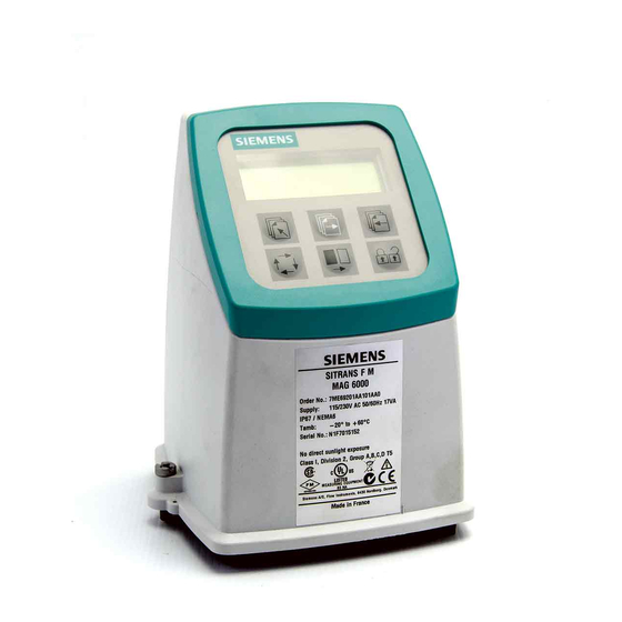
Introduction 1.3 History Device identification ① Code number ② Power supply ③ Enclosure rating ④ Ambient temperature ⑤ Approvals Figure 1-1 MAG 5000/6000 nameplate History This document describes: ● SITRANS F MAG 5000 and MAG 6000 transmitters (standard version). ● Optional versions: –... -
Page 12: Further Information
Product information on the Internet The Operating Instructions are available on the CD-ROM shipped with the device, and on the Internet on the Siemens homepage, where further information on the range of SITRANS F flowmeters may also be found: Product information on the internet (http://www.siemens.com/flow) - Page 13 Introduction 1.4 Further Information info@eltra-trade.com +421 552 601 099 www.eltra-trade.com...
-
Page 14: Safety Notes
Safety notes CAUTION Correct, reliable operation of the product requires proper transport, storage, positioning and assembly as well as careful operation and maintenance. Only qualified personnel should install or operate this instrument. Note Alterations to the product, including opening or improper repairs of the product, are not permitted. -
Page 15: Installation In Hazardous Location
Safety notes 2.2 Installation in hazardous location CE-marked equipment The CE mark symbolizes the compliance of the device with the following guidelines: ● EMC-guideline 89/336/EEC ● Low voltage guideline 73/23/EWG ● ATEX Directive 94/9/EG ● CT: (MI-001) Directive 2004/22/EC Installation in hazardous location WARNING Equipment used in hazardous locations must be Ex-approved and marked accordingly. - Page 16 Safety notes 2.2 Installation in hazardous location ● Appropriate cable connectors are used for the output cicuits: intrinsically safe: blue, non- intrinsically safe: black ● Sensor and transmitter are connected to the potential equalization. For intrinsically safe output circuits potential equalization must be maintained along the entire connection path. ●...
- Page 17 Safety notes 2.2 Installation in hazardous location info@eltra-trade.com +421 552 601 099 www.eltra-trade.com...
-
Page 18: Description
Description System components A SITRANS F M MAG 5000/6000 flowmeter system includes: ● Transmitter (type SITRANS F M MAG 5000/6000) ● Sensor (types: SITRANS F MAG 1100/1100F/3100/3100 P/5100 W) ● Communication module (optional) (types: HART, PROFIBUS PA/DP, MODBUS RTU RS 485, Foundation Fieldbus H1, Devicenet) ●... -
Page 19: Features
Description 3.4 Features ● Pulp and paper industry ● Steel industry ● Power generation; utility and chilled water industry Features Power supply 2 different types of power supply are available. A 12 ... 24 V AC/DC and a 115 ... 230 V AC switch mode type. -
Page 20: Mag 5000/Mag 6000 Versions
Description 3.5 MAG 5000/MAG 6000 versions MAG 5000/MAG 6000 versions The transmitters are designed in various versions and offer high performance and easy installation, commissioning and maintenance. Standard version The standard version is an IP67 version for compact or remote installation. Its robust design ensures a long lifetime if installed outdoors. - Page 21 Description 3.5 MAG 5000/MAG 6000 versions info@eltra-trade.com +421 552 601 099 www.eltra-trade.com...
-
Page 22: Installing/Mounting
Installing/Mounting Introduction ● SITRANS F flowmeters are suitable for indoor and outdoor installations. WARNING Installation in hazardous location Special requirements apply to the location and interconnection of sensor and transmitter. See "Installation in hazardous area" This chapter describes how to install the flowmeter in the compact version as well as in the remote version. -
Page 23: 4.2 Installation Conditions
Installing/Mounting 4.2 Installation conditions CAUTION See Cable requirements (Page 72) before installing transmitter Installation conditions Reading and operating the flowmeter is possible under almost any installation conditions because the display can be oriented in relation to the sensor. To ensure optimum flow measurement, attention should be paid to the following: Vibrations Figure 4-3... - Page 24 Installing/Mounting 4.2 Installation conditions Compact installation Medium temperature must be in accordance with the graphs showing max. ambient temperature as a function of medium temperature. Figure 4-4 Standard, blind and SV versions Figure 4-5 CT version Remote installation Cable length and type (as described in Cable requirements (Page 72)) must be used. For installation conditions for sensors, see respective sensor operating instructions.
-
Page 25: Mag 5000/6000 Compact
Installing/Mounting 4.3 MAG 5000/6000 compact MAG 5000/6000 compact Install MAG 5000 / MAG 6000 compact version 1. Remove and discard terminal box lid of sensor. 2. Ensure SENSORPROM memory unit is installed. ® 3. Fit M20 or ½" NPT cable glands for supply and output cables. 4. - Page 26 Installing/Mounting 4.3 MAG 5000/6000 compact 8. Mount connection plate in terminal box. Note Check that your connection board lines up with SENSORPROM unit, if not, move ® SENSORPROM unit to the other side of terminal box. ® SENSORPROM memory unit connections will be established automatically when ®...
-
Page 27: Remote Installation
Installing/Mounting 4.4 Remote installation Remote installation At sensor 1. Remove terminal box lid. 2. Remove SENSORPROM unit from sensor terminal box and mount it in terminal box of ® wall mounting unit. 3. Fit M20 or ½" NPT cable glands for cables. info@eltra-trade.com +421 552 601 099 www.eltra-trade.com... - Page 28 Installing/Mounting 4.4 Remote installation 4. Fit and connect electrode (1) and coil (2) cables as shown in Electrical connection (Page 36). Note Unscreened cable ends must be kept as short as possible. Electrode cable and coil cable must be kept separate to prevent interference. 5.
- Page 29 Installing/Mounting 4.4 Remote installation Wall mounting 1. Mount bracket on a wall or on a horizontal or a vertical pipe using ordinary hose clips or duct straps. Figure 4-6 Wall mounting Figure 4-7 Pipe mounting - vertical Figure 4-8 Pipe mounting - horizontal 2.
- Page 30 Installing/Mounting 4.4 Remote installation 3. Fit M20 or ½" NPT cable glands for cables from bottom or sides of terminal box. 4. Mount earth wire in bottom of terminal box. ① Connect electrode cable ② Connect coil cable - keep separate from electrode cable ③...
-
Page 31: Mag 5000/6000 Ct
Installing/Mounting 4.5 MAG 5000/6000 CT 8. Tighten cable glands to obtain optimum sealing. CAUTION When remote mounted, power supply PE wire must be connected to PE terminal ( Coil cable shield must be connected to SHIELD terminal. 9. Mount transmitter on terminal box. 10. -
Page 32: Installing Hardware Key
Installing/Mounting 4.5 MAG 5000/6000 CT 4.5.1 Installing hardware key Use hardware key on non-verified transmitter 1. Mount hardware key on transmitter connection plate during setting of primary operating parameters such as Q ., low-flow cut-off, units, approvals, etc. in connection with commissioning or calibration. - Page 33 Installing/Mounting 4.5 MAG 5000/6000 CT 1. Seal connection plate to prevent access to SENSORPROM memory unit as shown ® below. 1 indicates sealing locations. 2. Drill through marked drilling holes in terminal box and transmitter/lid. Seal transmitter externally as shown below. info@eltra-trade.com +421 552 601 099 www.eltra-trade.com...
-
Page 34: Installation Conditions
Installing/Mounting 4.6 Turning transmitter/keypad 4.5.3 Installation conditions 4.5.3.1 MI-001 MAG 5000/6000 CT together with MAG 5100W (7ME652) are approved for Mi-001 under the following installation conditions. ● DN 50 to 300 mm (2" to 12") ● Horizontal installation ● Compact or remote with max. 3 m cable ●... - Page 35 Installing/Mounting 4.6 Turning transmitter/keypad Transmitter Figure 4-9 Transmitter can be mounted with its front in either direction indicated by the arrows without turning terminal box Figure 4-10 Terminal box can be rotated ±90° in order to optimize viewing angle of transmitter display/keypad 1.
- Page 36 Installing/Mounting 4.6 Turning transmitter/keypad Keypad 1. Remove outer frame using a screwdriver. 2. Loosen the four screws retaining keypad. 3. Withdraw keypad and turn it to required orientation. info@eltra-trade.com +421 552 601 099 www.eltra-trade.com...
- Page 37 Installing/Mounting 4.6 Turning transmitter/keypad 4. Tighten the four screws until a mechanical stop is felt in order to obtain IP67 enclosure. 5. Snaplock outer frame onto keypad (click). info@eltra-trade.com +421 552 601 099 www.eltra-trade.com...
-
Page 38: Connecting
Connecting WARNING Mains supply from building installation Class II A switch or circuit breaker (Max. 15 A) must be installed in close proximity to the equipment and within easy reach of the operator. It must be marked as the disconnecting device for the equipment. -
Page 39: Electrical Connection
Connecting 5.1 Electrical connection Electrical connection Figure 5-1 Wiring diagram info@eltra-trade.com +421 552 601 099 www.eltra-trade.com... - Page 40 Connecting 5.1 Electrical connection Note Terminals 81 and 84 are only to be connected if special electrode cable with double screening is used, e.g. when empty pipe function or long cables are used. Mains supply Mains supply 115 ... 230 V AC from building installation Class II. Note For DC installations it is recommend to install an under voltage relay or protection circuit in the application where there is a risk of low power supply below the specifications for more...
-
Page 41: Electrical Connection Ptb K7.2
When the add-on module has been installed, the electrical connections are available on terminal rows 91-97. For more information Refer to the relevant BUS communication Quick Start or Operating Instructions available at the SITRANS F literature CD or on the internet, at : www.siemens.com/flowdocumentation (www.siemens.com/flowdocumentation). info@eltra-trade.com +421 552 601 099... -
Page 42: Commissioning
Commissioning In this chapter it is described how to commission the device via the local user interface (LUI). The display is described in details in section Local user interface (Page 40). Furthermore, the following functions are described in details: ● Changing password (Page 42) ●... -
Page 43: Local User Interface
Commissioning 6.2 Local user interface Local user interface Sign field Primary field for numeric value flow rate, Totalizer 1 or Totalizer 2) Unit field Title line with individual information according to operator or setup menu selected. Subtitle line which will either add information to the title line or keep individual information independent of the title line. -
Page 44: Menu Structure
Commissioning 6.3 Menu structure Lock field symbols Ready for change Access to submenu Value locked RESET MODE: Zero setting of totalizers and initialization of setting Keypad The keypad is used to set the flowmeter. The keys function as follows: TOP UP KEY This key (when held for 2 sec.) is used to switch between operator menu and setup menu. -
Page 45: Changing Password
Commissioning 6.4 Changing password Setup mode is a read and write mode. The pre-selected settings can be scanned and changed. Access to the setup mode is password-protected. The factory set password is 1000. Access to a submenu in the setup menu is gained by pressing the lock key . -
Page 46: Changing Basic Settings
Commissioning 6.5 Changing basic settings Changing basic settings In the basic settings menu it is possible to set the following parameters: Parameter Description Main frequency Selection of main power supply frequency corresponding to the country in which the flowmeter is installed (e.g. 60 Hz in America). Flow direction Selection of correct flow direction in pipe. - Page 47 Commissioning 6.5 Changing basic settings 9. Repeat steps 5-8 to change other settings. 10. Press top up key two times to exit setup mode. Decimal point can be positioned and units set individually for flow rate in totalizer 1 and totalizer 2.
-
Page 48: Changing Operator Menu Setup
Commissioning 6.6 Changing operator menu setup Changing decimal point position 1. Enter the respective totalizer menu. 2. Use select key to position cursor below decimal point. 3. Use change key to move decimal point to requested position. Changing units 1. Use select key to position cursor below unit. -
Page 49: Changing Language
Commissioning 6.7 Changing language 6. Use select key to move cursor to line 3. 7. Use change key to select desired setting. 8. Press lock/unlock key to confirm new setting. 9. Repeat steps 1-8 for each requested menu. Showing/hiding menus in operator menu 1. -
Page 50: Functions
Functions This chapter describes the various menus of the transmitter in details. The menu diagrams are shown in appendix menu diagrams. Output settings Three outputs are available: ● Current output (range and time constant); terminals 31 and 32. ● Digital output (pulse, frequency, error, limit, or batch settings); terminals 56, 57, and 58. ●... - Page 51 Functions 7.1 Output settings Digital output Digital output can be used to configure various settings: ● Pulse (volume/pulse, pulse output, pulse width, pulse polarity, and time constant), see pulse menu diagram. ● Frequency (frequency output, max frequency, and time constant), see frequency menu diagram.
-
Page 52: External Input
Functions 7.2 External input External input By applying 11 … 30 V DC to terminals 77 and 78, it is possible to perform: ● Batch control (start, stop, hold/continue) ● Reset totalizer ● Force/freeze output ● Q 2 (night) See external input menu diagram. Note Batch settings Only MAG 6000. - Page 53 Functions 7.4 Reset mode Resetting 1. Press top up key for 2 sec. 2. Enter password. 3. Use forward key or backward key to reach reset mode menu. 4. Press lock/unlock key to enter reset menu. 5. Press forward key to reach totalizer/counter to be reset or default setting menu.
-
Page 54: Service Mode
Functions 7.5 Service mode 8. Press forward key and then select key and change key to key in offset value. 9. Press lock/unlock key to start adjustment. Zero point can be adjusted manually in range -1.000 ... +1.000 m /s. If value outside this range is keyed in, zero point adjustment will not be implemented. -
Page 55: Mag 6000 Sv
Functions 7.7 MAG 6000 SV Output ● When choosing hot water, changing the output settings is not allowed and the output setting menus are not shown in display. ● When choosing cold water or other liquids, all output settings can be changed. MAG 6000 SV Excitation frequency The MAG 6000 SV excitation frequency can be changed in sensor characteristics menu to... -
Page 56: Alarm, Error, And System Messages
Alarm, error, and system messages Diagnostics Error system Transmitter system is equipped with an error and status log system with 4 groups of information. (I) Information - system will continue to measure as normal, relay and current outputs will not be affected. - Page 57 Alarm, error, and system messages 8.1 Diagnostics Acceptance levels The following three acceptance levels are selectable. ● Fatal error: Only fatal errors are registered as errors ● Permanent error: Permanent and fatal errors are registered as errors ● Warning (Default value): Warnings, permanent and fatal errors are registered as errors Error information is displayed in title and subtitle lines, see display layout (Page 40).
-
Page 58: List Of Error Numbers
Alarm, error, and system messages 8.2 List of error numbers List of error numbers Error text Error Comment Output Input Remedy text status status I1 - Power on Device powered on Active Active I2 - Add-on module Applied A new module has been applied to the system Active Active I3 - Add-on module... - Page 59 Alarm, error, and system messages 8.2 List of error numbers Error text Error Comment Output Input Remedy text status status P42 - Current output Check cables Current loop is disconnected or the loop resistance Active Active is too big P43 - Internal error Switch off and on Too many errors occurred at the same time.
-
Page 60: Service And Maintenance
It is a highly advanced instrument, which carries out the complex verification of the entire flowmeter system according to unique SIEMENS patented principles. The verification test is automated and the instrument easy to use, so no human error or influence will affect the verification. -
Page 61: Technical Support
Sensor check list Check list for sensors are included in the respective sensor operating instructions. Technical support NOTICE Repair and service must be carried out by approved Siemens Flow Instruments personnel only. Note Siemens Flow Instrument defines sensors as non-repairable products. -
Page 62: Return Procedures
● Information about field service, repairs, spare parts and lots more under "Services." Additional Support Please contact your local Siemens representative and offices if you have additional questions about the device Find your contact partner at: Local contact person (http://www.automation.siemens.com/partner) -
Page 63: Recalibration
You can find the forms on the Internet and on the CD delivered with the device. Recalibration Siemens A/S Flow Instruments offers to recalibrate the sensor. The following calibrations are offered as standard: ● Standard matched pair calibration... -
Page 64: Troubleshooting/Faqs
Troubleshooting/FAQs Symptom Output Error Cause Remedy signals code Empty display Minimum 1. No power supply Power supply Check MAG 5000/6000 for bended pins on the connector 2. MAG 5000/6000 defective Replace MAG 5000/6000 No flow signal Minimum 1. Current output disabled Turn on current output 2. - Page 65 Troubleshooting/FAQs Symptom Output Error Cause Remedy signals code Defective SENSORPROM Replace SENSORPROM unit ® ® unit Loss of internal data Replace MAG 5000/6000 Maximum Flow exceeds 100% of Qmax. Check Q (Basic Settings) Pulse overflow Volume/pulse too small Change volume/pulse Pulse width too large Change pulse width Measuring approx.
-
Page 66: Technical Data
Technical data 11.1 Technical specifications Mode of operation and design Measuring principle Electromagnetic with pulsed constant field Empty pipe Detection of empty pipe (special cable required in remote mounted installation) Excitation frequency Depends on sensor size Electrode input impedance > 1 x 10 Ω... - Page 67 Technical data 11.1 Technical specifications MAG 6000 0.2% ± 1 mm/s (for v > 0.1 m/s) Functions Flow rate, 2 totalizers, low-flow cut-off, empty pipe cut-off, flow direction, error system, operating time, uni/bidirectional flow, limit switches, pulse output, control for cleaning and batch Rated operation conditions Ambient temperature...
- Page 68 Technical data 11.1 Technical specifications Transmitter IP67/NEMA 4X/6 compact polyamide Weight: MAG 5000/6000: 0.75 kg (1.65 lbs) Transmitter IP67/NEMA 4X/6 wall-mounted polyamide Weight(transmitter and wall mounting bracket): 1.65 kg (3.64 lbs) info@eltra-trade.com +421 552 601 099 www.eltra-trade.com...
-
Page 69: Accuracy
Technical data 11.2 Accuracy 11.2 Accuracy For accuracy reference conditions, please see below. Figure 11-1 MAG 5000 with MAG 1100, MAG 1100 F, MAG 5100 W, MAG 3100 and MAG 3100 P and MAG 6000 with MAG 1100 (PFA), MAG 1100 F (PFA) info@eltra-trade.com +421 552 601 099 www.eltra-trade.com... - Page 70 Technical data 11.2 Accuracy Figure 11-2 MAG 6000 with MAG 1100 (not PFA), MAG 1100 F (not PFA), MAG 5100 W, MAG 3100 and MAG 3100 P Reference conditions (ISO 9104 and DIN/EN 29104) A calibration certificate is shipped with every sensor and calibration data are stored in SENSORPROM memory unit.
-
Page 71: Output Characteristics
Technical data 11.3 Output characteristics Current output As pulse output ± (0.1% of actual flow + 0.05% FSO) Effect of ambient temperature Display/frequency/pulse output < ± 0.003% / °C act. Current output < ± 0.005% / °C act. Effect of supply voltage <... - Page 72 Technical data 11.3 Output characteristics Pulse output Bidirectional mode Unidirectional mode Relay output Bidirectional mode Unidirectional mode Power down Active Error relay output Bidirectional mode Unidirectional mode No error Error Limit switch (can be used as direction switch) 1 set point 2 set points Passive Digital output Passive Digital output...
- Page 73 Technical data 11.3 Output characteristics 1 set point 2 set points Note Active digital output is not avaiable with MAG 6000 I. Batch on digital output Unidirectional mode (forward flow only) Totalizer lap info@eltra-trade.com +421 552 601 099 www.eltra-trade.com...
-
Page 74: Cable Data
Technical data 11.4 Cable data Batch on relay output Unidirectional mode (forward flow only) Hold Batch 11.4 Cable data Description Cable for standard electrode or coil Electrode cable, double shielded Cable kit with standard coil cable and electrode cable double shielded (also available as low noise cable for MAG 1100 sensor ) Technical data... -
Page 75: Cable Requirements
Technical data 11.5 Cable requirements 11.5 Cable requirements Coil Electrode cable cable Basic data No. of conductors Min. sqr. area 0.5 mm 0.2 mm Screen Max. capacitance 350 pF/m Max. cable loop resistance Media temperature: < 100 °C 40 Ω >... -
Page 76: Spare Parts/Accessories
Spare parts/Accessories 12.1 Ordering In order to ensure that the ordering data you are using is not outdated, the latest ordering data is always available on the Internet: Catalog process instrumentation (http://www.siemens.com/processinstrumentation/catalogs) 12.2 Accessories Description Wall mounting unit Display protection lid Communication modules for MAG 6000 info@eltra-trade.com... -
Page 77: Spare Parts
Spare parts/Accessories 12.3 Spare parts 12.3 Spare parts Description Connection plate SENSORPROM memory unit ® Display unit Communication modules for MAG 6000 12.4 Sun shield Description Sun shield info@eltra-trade.com +421 552 601 099 www.eltra-trade.com... -
Page 78: A Menu Diagrams
Menu diagrams Transmitter menu overview The menu diagrams shown on the following pages apply to MAG 5000/6000 as well as MAG 6000 I. Not available in MAG 5000 Add-on module Factory-set password: 1000 Not available when batch Only available when batch info@eltra-trade.com +421 552 601 099 www.eltra-trade.com... -
Page 79: Basic Settings
Menu diagrams A.2 Basic settings Basic settings The question mark at unit selections stand for customer units. The unit is shown as a question mark on display if not overwritten with customer's own unit text setup using PDM or ordered specially using Y20 in ordering system. -
Page 80: Current Output
Menu diagrams A.3 Current output Current output If HART communication is installed, it is not possible to set the output for 0-20 mA (even though the option is visible in the display). This is due to the fact that HART does not work if the output falls below 2-3 mA. -
Page 81: Digital Output - Pulse
Menu diagrams A.4 Digital output - pulse Digital output - pulse Digital output - frequency Error level info@eltra-trade.com +421 552 601 099 www.eltra-trade.com... -
Page 82: Error Number
Menu diagrams A.7 Error number Error number Direction/limit Batch Visible only on Digital output. Note If batch function is chosen on the relay output, the digital output will be turned off if it has been set up for pulse, frequency or batch. If digital output is set up for pulse, frequency or batch, then the relay output will be turned off if it has been set up for batch. -
Page 83: External Input
Menu diagrams A.10 External input A.10 External input The value showing totalizer 1 on the display is frozen for as long as the digital output is activated. However, totalizer 1 continues counting, and when the digital input is released, the value on the display again follows totalizer 1. -
Page 84: Sensor Characteristics
Menu diagrams A.11 Sensor characteristics A.11 Sensor characteristics Error status (level or number) on an output is updated only at the time the error status changes (occurs or disappears). If P40 is suppressed after it has been detected (at power up), the output does not change state. -
Page 85: Reset Mode
Menu diagrams A.12 Reset mode A.12 Reset mode info@eltra-trade.com +421 552 601 099 www.eltra-trade.com... -
Page 86: Reset Mode - Mag 6000 Sv
Menu diagrams A.13 Reset mode - MAG 6000 SV A.13 Reset mode - MAG 6000 SV info@eltra-trade.com +421 552 601 099 www.eltra-trade.com... -
Page 87: Service Mode
Menu diagrams A.14 Service mode A.14 Service mode Signal suitability is a level from 0 to 9 of the electrode measured voltage. Level 0 is equal to the limit value that is set for empty pipe error detection, and level 9 is the best signal measured. If digital output is set to pulse (standard). -
Page 88: Operator Menu Setup
Menu diagrams A.15 Operator menu setup A.15 Operator menu setup When selecting Batch amount for upper line, the upper line is initially blank. The amount done may not appear until the batch is started. 'Text' means that the text for the chosen measured value is shown. For example, if textis chosen in line 2 and flow velocity is chosen in line 3, the text "Flow velocity "... -
Page 89: Product Identity
Menu diagrams A.16 Product identity A.16 Product identity info@eltra-trade.com +421 552 601 099 www.eltra-trade.com... -
Page 90: Add-On Communication Module
Menu diagrams A.17 Add-on communication module A.17 Add-on communication module Example: HART Note Burst mode is not available with HART communication A.18 Cleaning Note Relay outputs If cleaning unit is installed, relay outputs must always be used to operate cleaning. Relay outputs cannot be used for other purposes info@eltra-trade.com +421 552 601 099... -
Page 91: Mag 5000/6000 Ct Menu Overview
Menu diagrams A.19 MAG 5000/6000 CT menu overview A.19 MAG 5000/6000 CT menu overview Figure A-1 Overview MAG 5000 CT and MAG 6000 CT (part 1) Factory-set password: 1000 Not visible when CT mode is "Hot water" Figure A-2 Overview MAG 5000 CT and MAG 6000 CT (part 2) info@eltra-trade.com +421 552 601 099 www.eltra-trade.com... -
Page 92: Change Password
Menu diagrams A.20 Change password Note Sealing Menus marked with gray are locked when transmitter is sealed. A.20 Change password info@eltra-trade.com +421 552 601 099 www.eltra-trade.com... -
Page 94: B Factory Settings
Factory settings Transmitter factory settings The factory settings shown on the following pages apply to MAG 5000/6000 as well as MAG 6000 I. Menu item Parameter Factory Options More info settings Password Password 1000 1000 ... 9999 Changing password (Page 42) and Change password (Page 89) - Page 95 Factory settings B.1 Transmitter factory settings Menu item Parameter Factory Options More info settings Digital output Pulse Error, direction/limit, batch, frequency, pulse, error Digital number, off output - pulse (Page 78) Relay output Error level Error, direction/limit, cleaning, error number, off Error level (Page 78) Direction/limit...
-
Page 96: 50 Hz Dimension Dependent
Factory settings B.2 50 Hz Dimension dependent Menu item Parameter Factory Options More info settings Sensor Correction factor 0.85 ... 2.00 Sensor characteristics characteristi (Page 81) Language Language English English, German, French, Danish, Swedish, Changing Finnish, Spanish, Russian, Italian, Portuguese, language Polish (Page 46) -
Page 97: B.3 60 Hz Dimension Dependent
Factory settings B.3 60 Hz Dimension dependent max* Factory MAG 5100 W (Order no. 7ME6520) MAG 1100, MAG 1100 F, 5100 W unit settting (Order no. 7ME6580) MAG 3100, 3100 P mm (inch) min. max. min. max. 400 (16) 1800 113.0974 4523.893 113.0974... - Page 98 Factory settings B.3 60 Hz Dimension dependent 60 Hz Dimension dependent 60 Hz Dimension dependent factory settings MAG 1100, MAG1100F, MAG 3100, MAG 3100 P and MAG 5100W with ½" NPT cable glands Factory MAG 5100 W (Order no. 7ME6520) MAG 1100, MAG 1100 F, 5100 W unit setting* (Order no.
-
Page 99: 50 Hz Dimension Dependent Batch And Pulse Output Settings
Factory settings B.4 50 Hz Dimension dependent batch and pulse output settings Factory MAG 5100 W (Order no. 7ME6520) MAG 1100, MAG 1100 F, 5100 W unit setting* (Order no. 7ME6580) MAG 3100, 3100 P mm (inch) min. max. min. max. -
Page 100: 60 Hz Dimension Dependent Batch And Pulse Output Settings
Factory settings B.4 50 Hz Dimension dependent batch and pulse output settings Volume/pulse or batch quantity* Factory setting MAG 5100 W (Order no. MAG 1100, MAG 1100 F, 5100 W (Order Volume/ Pulse & Totalize 7ME6520) no. 7ME6580) MAG 3100, 3100 P pulse &... - Page 101 Factory settings B.5 60 Hz Dimension dependent batch and pulse output settings 60 Hz Dimension dependent batch and pulse output settings 60 Hz Dimension dependent factory settings MAG 1100, MAG1100F, MAG 3100, MAG 3100 P and MAG 5100W with ½" NPT cable glands Volume/pulse or batch quantity MAG 5100 W (Order no.
- Page 102 Factory settings B.5 60 Hz Dimension dependent batch and pulse output settings Volume/pulse or batch quantity MAG 5100 W (Order no. 7ME6520) MAG 1100, MAG 1100 F, 5100 W (Order no. 7ME6580) MAG 3100, 3100 P mm (inch) US G min. US G max.
- Page 103 info@eltra-trade.com +421 552 601 099 www.eltra-trade.com...
-
Page 104: C Approvals/Certificates
Approvals/Certificates All certificates are posted on the Internet. Additionally, the CE Declaration of Conformity as well as ATEX approvals are available on the SITRANS F literature CD-ROM. Certificates (http://support.automation.siemens.com/WW/view/en/10806951/134200) - Page 105 Approvals/Certificates info@eltra-trade.com +421 552 601 099 www.eltra-trade.com...
-
Page 106: Index
Index Add-on module, 15 Laws and directives, 11 Add-on modules Electrical connection:Add-on modules, 38 Alarm differentiation, 47 Alarm level, 47 Mains supply, 35 Maintenance, 57 Communication module, (See Add-on module) Compliance, 11 Protective conductor terminal, 35 Contact person, 9 Protective earth, 35 Customer Support Hotline, 58 Recalibration, 60 Decontamination, 59... - Page 107 We supply: SITRANS FM Magflo Eltra Trade s.r.o. supplies full range of SIEMENS SITRANS F SIEMENS MAG 1100 products with the best prices SIEMENS MAG 3100 and delivery terms. SIEMENS MAG 5100 Ø SIEMENS MAG 8000 ...
Need help?
Do you have a question about the SITRANS F M MAG 5000 and is the answer not in the manual?
Questions and answers