Furuno FS-5075 Operator's Manual
Ssb radiotelephone
Hide thumbs
Also See for FS-5075:
- Service manual (609 pages) ,
- Operator's manual (191 pages) ,
- Installation manual (88 pages)
Table of Contents
Advertisement
Quick Links
Advertisement
Table of Contents
Troubleshooting

Related Manuals for Furuno FS-5075


Summary of Contents for Furuno FS-5075
- Page 1 OPERATOR'S MANUAL SSB RADIOTELEPHONE FS-2575 FS-5075 MODEL www.furuno.co.jp...
- Page 2 The paper used in this manual is elemental chlorine free. ・FURUNO Authorized Distributor/Dealer 9-52 Ashihara-cho, Nishinomiya, 662-8580, JAPAN Telephone : +81-(0)798-65-2111 : +81-(0)798-65-4200 0000 Printed in Japan All rights reserved. Z : FEB . 25, 2011 Pub. No. OME-56770-Z *00017516510*...
- Page 3 (http://www.eiae.org/) for the correct method of disposal. How to discard a used battery Some FURUNO products have a battery(ies). To see if your product has a battery, see the chapter on Maintenance. Follow the instructions below if a battery is used. Tape the + and - terminals of battery before disposal to prevent fire, heat generation caused by short circuit.
-
Page 4: Safety Instructions
High voltage which will cause death or Continued use of the equipment can cause serious injury is present at the locations fire or electrical shock. Contact a FURUNO shown in the illustration below when the agent for service. SSB radiotelephone is transmitting. - Page 5 Injury can result if the LCD breaks. WARNING LABELS Warning labels are attached to the equipment. Do not remove any label. If a label is missing or damaged, contact a FURUNO agent or dealerabout replacement. Name: Warning Label 1 Name: Warning Label...
- Page 6 TABLE OF CONTENTS FOREWORD ......................ix SYSTEM CONFIGURATIONS ................xi 1. OPERATIONAL OVERVIEW................. 1-1 1.1 Controls........................1-1 1.2 How to Turn On/Off the Power................... 1-2 1.3 Radiotelephone (RT) Screen ..................1-3 1.4 DSC Scan Screen ..................... 1-4 1.5 How to Adjust LCD and Key Panel Brilliance ............. 1-4 1.6 How to Turn On/Off the Main Speaker ...............
- Page 7 TABLE OF CONTENTS 4. DISTRESS OPERATIONS ................4-1 4.1 Sending Distress Alert ....................4-1 4.1.1 Sending distress alert by DISTRESS key with distress information not edited. 4-2 4.1.2 Sending distress alert by DISTRESS key with distress information edited..4-3 4.2 Receiving a DISTRESS Alert ..................4-5 4.2.1 Distress alert received on MF band ..............
- Page 8 TABLE OF CONTENTS 6.3 Log File ........................6-5 6.3.1 Opening a log file.................... 6-5 6.3.2 Deleting log files ..................... 6-6 6.4 Squelch Frequency ....................6-6 6.5 Key Assignment ......................6-7 6.6 Printing Messages..................... 6-8 6.7 Position Setting ......................6-8 6.8 Date and Time Setting....................6-9 6.9 Timeout Setting ......................6-10 6.10 FAX Enable/Disable ....................6-11 6.11 Selecting Antenna ....................6-11...
- Page 9 TABLE OF CONTENTS 8.2.2 Editing/Deleting stations .................. 8-4 8.3 Timer Programming ....................8-5 8.3.1 Registering timer programs ................8-5 8.3.2 Editing/Deleting timer programs ..............8-6 8.4 User Channels......................8-6 8.4.1 Registering user channels ................8-6 8.4.2 Editing/Deleting user channels ................ 8-7 8.5 Scan Channel Groups ....................
- Page 10 TABLE OF CONTENTS 10.9.3 Commands ....................10-11 10.9.4 Store-and-forward method ................10-12 10.10 Automatic Telex Using Macrofile ................10-15 11. MAINTENANCE & TROUBLESHOOTING ..........11-1 11.1 Test ..........................11-1 11.2 Maintenance......................11-2 11.3 Simple Troubleshooting....................11-3 11.4 Error Messages......................11-4 11.5 Breaker PR-850A .....................11-5 11.6 Test Call ........................11-5 11.7 NBDP Terminal Unit Maintenance ................11-6 11.7.1 Cleaning the equipment .................11-6 11.7.2 Connectors and earth connection ..............11-6...
- Page 11 A Word to the Owner of the FS-2575/5075 Congratulations on your choice of the FURUNO FS-2575/5075 SSB Radiotelephone. We are confident you will see why the FURUNO name has become synonymous with quality and reliability. For over 60 years FURUNO Electric Company has enjoyed an enviable reputation for innovative and dependable marine electronics equipment.
- Page 12 FOREWORD DSC/watch receiver Distress, urgency, safety and general calling • Scanning of DSC frequencies for distress and general calls on MF/HF • File editing capability for readiness in case of emergency • PSTN (Public Switched Telephone Network) capability standard • Log stores 50 each of latest ordinary, distress and transmitted messages, in separate •...
- Page 13 SYSTEM UNIT PP-510 FS-2575T (FS-2575) PRINTER EXTERNAL NBDP TERMINAL UNIT INTERFACE EQUIPMENT FS-5075T IB-583 IF-8500* (FS-5075) Required for NBDP Terminal 24 VDC and DSC to share printer. ALARM UNIT IC-350 CONTROL UNIT HANDSET FS-2575C HS-2003 BK INTERFACE BK-300 LOUDSPEAKER SEM-21Q...
- Page 14 SYSTEM CONFIGURATIONS This page is intentionally left blank.
-
Page 15: Operational Overview
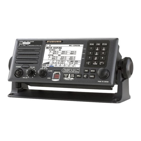
OPERATIONAL OVERVIEW Controls SCAN 2182 RT/CH 34°42 . 2800 ’ N 135°19 . 5900 ’ E TUNE VOLUME RF GAIN Keep pressed for 4 s in HANDSET case of DISTRESS. PUSH TO ATT MENU The alert is transmitted ALARM with steady lighting. DISTRESS OTHER BRILL... -
Page 16: How To Turn On/Off The Power
1. OPERATIONAL OVERVIEW Control Function • Open the scan screen. SCAN key • Stop/start the scanning of DSC general frequencies, on the scan screen. 2182 key Switch to the RT (radiotelephone) screen and set SSB: 2182.0 kHz • Switch to the RT (radiotelephone) screen. RT/CH key •... -
Page 17: Radiotelephone (Rt) Screen
Class of Emission OFF/SLOW/FAST Auto gain control (OFF: no adjustment, SLOW: low-speed, (AGC) FAST: high-speed) HIGH/MID/LOW(1)/ Output power (LOW2: FS-5075 only, minimum output power) LOW2 SIMP/S-DUP/DUP Communication mode (SIMP: simplex, S-DUP: semi-duplex, DUP: full-duplex (only for FS-5075, option)) IA/IC/VC/RF/VS Transceiver unit status (IA: antenna current, IC: collector current, VC: collector voltage, RF: RF output, VS: source voltage) S-meter, displays the strength of received signal. -
Page 18: Dsc Scan Screen
1. OPERATIONAL OVERVIEW DSC Scan Screen Press the SCAN key to show the DSC scan screen. This screen scans and receives the distress and general frequencies. WR2: The optional antenna for the routine frequency RX: Transceiver unit Maximum six distress and routine frequencies scanned. -
Page 19: How To Set The Scan Frequencies
1. OPERATIONAL OVERVIEW How to Set the Scan Frequencies The DSC screen scans multiple general frequencies according to operator-set interval. For how to set frequency to scan, see section 6.16. Note that voice and telex communication are not available when scanning. (However, they are available when the system is equipped with the optional watch receiver.) 2. -
Page 20: Intercom
1. OPERATIONAL OVERVIEW 1.10 Intercom The built-in intercom permits voice communications between two control units. Calling up You can call up with both on hook and off hook. 1. Press the MENU key. 2. Rotate the ENTER knob to select INTERCOM and then press the ENTER knob. The called party’s control unit rings. -
Page 21: Ssb Radiotelephone
SSB RADIOTELEPHONE You can use the SSB communication in any screen which displays the communication frequency. How to Select the Class of Emission You can select the emission mode. • SSB: Single Sideband • TLX: Telex • AM: AM (Only receiving) •... -
Page 22: How To Select The Channel, Frequency
2. SSB RADIOTELEPHONE How to Select the Channel, Frequency Select the channel or transmitting/receiving frequency to use for the SSB. Note: To set the SSB radiotelephone to 2182 kHz/J3E, press the 2182 key. Channel 1. Rotate the ENTER knob to select CH on the RT screen and then press the ENTER knob. You can also show the channel setting window by pressing RT/CH key. -
Page 23: Transmitting
RT screen. If tuning fails, the message “TUNE NG” appears and the output power is automatically set to LOW (for FS-2575) or LOW2 (for FS-5075). 2. Hold the handset close to your mouth, press the PTT switch and speak clearly. -
Page 24: Reducing Transmitter Power
LOW2 110Wpep Note: Power amplifier temperature is monitored, and when its temperature rises above a certain temperature, output power is automatically reduced. For FS-5075, when the over current is detected, output power is automatically reduced. 2.3.3 Condition of the transmitting unit... -
Page 25: Receiving
2. SSB RADIOTELEPHONE Checking the transmitting power During transmission, the IA bar deflects according to the current being fed to the antenna feeder from the antenna coupler. The unit of readout is amperes. The antenna current varies with the effective antenna impedance. The reading differs by the frequency and antenna length. -
Page 26: Receiving Am Broadcasting Stations
2. SSB RADIOTELEPHONE 2.4.3 Receiving AM broadcasting stations 1. When the RT screen is not displayed, press the RT key to display the RT screen. 2. Rotate the ENTER knob to select emission mode and then press the ENTER knob. 3. -
Page 27: User Channels
The USER CH menu provides for registration of user TX and RX channels, where permitted by the Authorities. For further details, contact your dealer. See section 6.2 to register. NOTICE FURUNO will assume no responsibility for the disturbance caused by the unlawful or improper setting of user... - Page 28 2. SSB RADIOTELEPHONE This page is intentionally left blank.
-
Page 29: Dsc Overview
DSC OVERVIEW What is DSC? DSC is an acronym meaning Digital Selective Calling. It is a digital distress and general calling system in the MF and HF bands used by ships for transmitting distress alerts and general calls and by coast stations for transmitting the associated acknowledgements. For DSC distress and safety calling in the MF and HF bands, the frequencies are 2187.5, 4207.5, 6312.0, 8414.5, 12577.0, and 16804.5 kHz. - Page 30 3. DSC OVERVIEW Contents of a DSC call • Calling category Call category Call DISTRESS ALERT, DISTRESS RELAY AREA, DISTRESS RELAY DISTRESS INDIVIDUAL MEDICAL MSG, NEUTRAL MSG, INDIVIDUAL MSG, PSTN MSG, TEST GENERAL MSG, GROUP MSG, AREA MSG, POSITION MSG, POLLING MSG •...
-
Page 31: Audio Alarms
3. DSC OVERVIEW Audio Alarms When you receive a distress alert or general call addressed to your ship, the audio and visual alarms are released. The audio alarm sounds until the CANCEL key is pressed. Alarm Frequency (interval) Safety call received 750 Hz and 650 Hz (50 ms) Routine call received 750 Hz and 650 Hz (50 ms) -
Page 32: Send Calls
3. DSC OVERVIEW Individual receive call Icon Working frequency to use Elapsed time Call type ID No. (MMSI) of ship sending this Priority (Routine, Safety, Urgency) message Communication mode Communication frequency Available user options Icon in progress RF gain 3.4.2 Send calls Below are sample distress alert and individual send call. -
Page 33: Distress Operations
DISTRESS OPERATIONS Distress operation overview 1. Press the DISTRESS key. 2. Wait for the distress alert acknowledgement. 3. Communicate with the coast station. Your ship Coast Ship in station distress (Your ship) (1) Ship in distress sends Distress Alert. (2) Coast station sends distress acknowledgement (DIST ACK). (3) Voice or telex communications between ship in distress and coast station. -
Page 34: Sending Distress Alert By Distress Key With Distress Information Not Edited
4. DISTRESS OPERATIONS 4.1.1 Sending distress alert by DISTRESS key with distress information not edited 1. Open the DISTRESS key cover and then press the DISTRESS key for four seconds. The audio alarm sounds during pressing the key, and the key flashes in red. The countdown message appears on the screen during pressing the DISTRESS key (3S →... -
Page 35: Sending Distress Alert By Distress Key With Distress Information Edited
4. DISTRESS OPERATIONS When the distress acknowledge call is received, the audio alarm sounds, the LED flashes in red, the icon for DISTRESS transmitting ( ) flashes. The screen changes as below. DISTRESS ACK received! [CANCEL]: Stop alarm 2. Press the CANCEL key to silence the audio alarm. The LED and the icon stop to flash, and the pop-up message disappears. - Page 36 4. DISTRESS OPERATIONS 3. Rotate the ENTER knob to select nature of distress among the following 11 options and then press the ENTER knob. • • • UNDESIGNATED FIRE FLOODING • • • COLLISION GROUNDING LISTING • • • SINKING DISABLED&ADRIFT ABANDONING •...
-
Page 37: Receiving A Distress Alert
Mode : ARQ FEC ABC-8M Tx Freq : 2174.50 FURUNO Rx Freq : 2174.50 4. DSC is selected; press the Enter key to connect the communications line. Connect appears in reverse video. 5. Type and transmit your message, giving the following information: •... -
Page 38: Distress Alert Received On Mf Band
4. DISTRESS OPERATIONS option ACTIVE appears to start the new procedure. The steps throughout this manual are for the ACTIVE option. 4.2.1 Distress alert received on MF band Do the following: Continue watching on 2182 kHz. Wait for coast station to acknowledge the distress call. •... - Page 39 4. DISTRESS OPERATIONS Sending the distress acknowledge call to ship in distress (on MF band) Note: You cannot send the distress acknowledge call for five minutes because of receiving the distress acknowledgement from the coast station. Transmit the distress acknowledge call to the ship in distress only when you do not receive it from a coast station and you are able to aid the ship in distress.
-
Page 40: Distress Alert Received On Hf Band
4. DISTRESS OPERATIONS 4.2.2 Distress alert received on HF band If you receive a distress alert on the HF band, the audio alarm sounds and the LED flashes in red. The icon for DISTRESS receiving ( ) on the tab area flashes and the pop-up message “DISTRESS ALERT message received! [CANCEL]: Stop alarm”... - Page 41 4. DISTRESS OPERATIONS Action for ships receiving distress alert on HF band DSC Distress alert received. HF DSC, RTF AND NBDP CHANNELS (kHz) RTF* NBDP Press the CANCEL 4207.5 4125 4177.5 key to silence alarm. 6312.0 6215 6268 8414.5 8291 8376.5 12577.0 12290...
-
Page 42: Sending Distress Relay On Behalf Of A Ship In Distress
4. DISTRESS OPERATIONS 8. Rotate the ENTER knob to select DSC FREQ and then press the ENTER knob. 9. Rotate the ENTER knob to select appropriate frequency and then press the ENTER knob. You should first select 8414.5 kHz. 10. Rotate the ENTER knob to select GO TO CALL and then press the ENTER knob. The screen changes to one for transmitting. -
Page 43: Sending Distress Relay To Area Ships
4. DISTRESS OPERATIONS 13. Rotate the ENTER knob to select appropriate frequency and then press the ENTER knob. 14. Rotate the ENTER knob to select GO TO CALL and then press the ENTER knob. The distress relay is transmitted to the coast station. The screen changes to one for transmitting. -
Page 44: Receiving Distress Relay From Coast Station
4. DISTRESS OPERATIONS 13. Rotate the ENTER knob to select TELEPHONE or NBDP-FEC and then press the ENTER knob. 14. Rotate the ENTER knob to select DSC FREQ and then press the ENTER knob. 15. Rotate the ENTER knob to select appropriate frequency and then press the ENTER knob. - Page 45 4. DISTRESS OPERATIONS 5. Communicate with all ships via radiotelephone referring to the illustration at step 4. 6. Press the ENTER knob. The screen for the selection of frequency appears (see the illustration at step 3). Asterisk marks the frequency over which the cancellation call by voice was completed.
- Page 46 4. DISTRESS OPERATIONS This page is intentionally left blank. 4-14...
-
Page 47: General Message Calling, Receiving
GENERAL MESSAGE CALLING, RECEIVING Operation overview The following shows about the individual message as example of the general message. The individual call is for sending a call to a specific station. 1. Send the individual message. 2. Wait for the individual message acknowledgement. 3. - Page 48 5. ROUTINE MESSAGE CALLING, RECEVING 2. Rotate the ENTER knob to select MSG TYPE and then press the ENTER knob. 3. Rotate the ENTER knob to select INDIVIDUAL MSG and then press the ENTER knob. 4. Rotate the ENTER knob to select TO and then press the ENTER knob. 5.
- Page 49 5. ROUTINE MESSAGE CALLING, RECEVING Routine priority a) Rotate the ENTER knob to select CHANNEL or FREQUENCY and then press the ENTER knob. b) Enter TX/RX frequency or channel referring to section 2.2. Urgency or safety priority For urgency or safety priority the communication frequency cannot be selected; it is automatically set to the pair frequency as set for the DSC frequency.
- Page 50 5. ROUTINE MESSAGE CALLING, RECEVING b) Rotate the ENTER knob to select appropriate frequency and then press the ENTER knob. 15. Rotate the ENTER knob to select GO TO CALL and then press the ENTER knob to send the individual call. The screen is changed to one for transmission and the pop-up message “Sending DSC MSG.“...
-
Page 51: Receiving An Individual Call
5. ROUTINE MESSAGE CALLING, RECEVING Unable acknowledge call received 1. Press the CANCEL key to silence the audio alarm. The pop-up message disappears. The reason for UNABLE ACK is displayed on the receiving screen. Reason for unable to acknowledge • •... - Page 52 5. ROUTINE MESSAGE CALLING, RECEVING Communicating by NBDP terminal unit After acknowledging an individual call, do the following to communicate by NBDP terminal unit. The control unit’s screen shows “OCCUPIED” and the TX and RX frequencies. The message from the other party appears on your NBDP terminal unit. 1.
-
Page 53: Group Call
5. ROUTINE MESSAGE CALLING, RECEVING Group Call A group call is for calling a specific group by specifying its group ID. 5.2.1 Sending a group call 1. Press the OTHER DSC MSG key. 2. Rotate the ENTER knob to select MSG TYPE and then press the ENTER knob. 3. -
Page 54: Receiving A Group Call
5. ROUTINE MESSAGE CALLING, RECEVING Sending message by NBDP terminal unit The message “STATION ENTRY COMPLETED FROM DSC. Press any key to escape.” appears on the screen of the NBDP terminal unit. 1. Press any key on the NBDP terminal unit to erase the message. 2. -
Page 55: Geographical Area Call
5. ROUTINE MESSAGE CALLING, RECEVING Geographical Area Call The geographical area call is for sending a call to all ships within the area you designate in your geographical area call. In the figure below, for example, the call will be sent to all ships within 24-34°N, 135-140°W (QUADRANT) and 34°N, 140°W, range: 500 NM (CIRCLE). - Page 56 5. ROUTINE MESSAGE CALLING, RECEVING 5. Rotate the ENTER knob to select CIRCLE or QUADRANT and then press the ENTER knob. 6. For QUADRANT: Using the numeric keys, enter latitude and longitude of reference point and southerly degrees and easterly degrees of area. To change coordinate, select it and press the 1 key for North or East;...
-
Page 57: Receiving A Geographical Area Call
5. ROUTINE MESSAGE CALLING, RECEVING 5.3.2 Receiving a geographical area call When you receive an area message, the audio alarm sounds. The icon ( ) on the tab area flashes in black and white, and the pop-up message “URGENCY (SAFETY) AREA MSG received! [CANCEL]: Stop alarm”... - Page 58 5. ROUTINE MESSAGE CALLING, RECEVING 4. Rotate the ENTER knob to select NEUTRAL MSG and then press the ENTER knob. PRIORITY is automatically selected to URGENCY. 5. Rotate the ENTER knob to select AREA and then press the ENTER knob. 6.
-
Page 59: Receiving A Neutral Craft Call
5. ROUTINE MESSAGE CALLING, RECEVING 5.4.2 Receiving a neutral craft call When you receive a neutral craft call, the audio alarm sounds. The icon ( ) on the tab area flashes in black and white, and the pop-up message “NEUTRAL MSG received! [CANCEL]: Stop alarm”... -
Page 60: Receiving A Medical Transport Call
5. ROUTINE MESSAGE CALLING, RECEVING 5. Rotate the ENTER knob to select AREA and then press the ENTER knob. 6. Enter the area range referring to step 5 to 7 in paragraph 5.3.1. 7. Rotate the ENTER knob to select COMM MODE and then press the ENTER knob. 8. -
Page 61: Receiving A Polling Request
5. ROUTINE MESSAGE CALLING, RECEVING 5. Watch on the working frequency. Communicate by radiotelephone or NBDP (see “Receiving message by NBDP terminal unit” on this page). If there is the difference between the registered frequency and used frequency to receive, the pop-up message appears. -
Page 62: Position Call
5. ROUTINE MESSAGE CALLING, RECEVING Position Call There are two types of position calls: other station requires your ship’s position and your ship requests position of another ship. Finding position of other station (1) Position request call (2) Position Information Your Station Other Station Sending your ship’s position to other station... -
Page 63: Position Call: Other Ship Requests Your Position
5. ROUTINE MESSAGE CALLING, RECEVING 4. Rotate the ENTER knob to select TO and then press the ENTER knob. 5. Rotate the ENTER knob to select DIRECT INPUT or ADDRESS BOOK DATA and then press the ENTER knob. 6. For ADDRESS BOOK DATA, select an ID from the ADDRESS BOOK (see section 6.14). 7. -
Page 64: Pstn Call
5. ROUTINE MESSAGE CALLING, RECEVING When you send the ACK with no position information, rotate the ENTER knob to select • UNABLE and then press the ENTER knob. PSTN Call The PSTN call allows the making and receiving of telephone calls over public switched telephone networks. - Page 65 5. ROUTINE MESSAGE CALLING, RECEVING 14. Rotate the ENTER knob to select GO TO CALL and then press the ENTER knob. The PSTN call is sent. After the call has been sent, the screen for waiting ACK appears. The elapsed time since sending the call and the count down time for re-sending the call (25 seconds) is displayed.
-
Page 66: Receiving A Pstn Call
5. ROUTINE MESSAGE CALLING, RECEVING 5.8.2 Receiving a PSTN call When a PSTN call is received, the icon appears on the tab area. An able/unable acknowledge is sent automatically. When the setting of REPLY TYPE on the ACK SETTING is ABLE, the automatic able acknowledge which means you can call with party is sent. When the setting of REPLY TYPE on the ACK SETTING is UNABLE, the automatic unable acknowledge which means you cannot call with party is sent. -
Page 67: Menu Operation
MENU OPERATION The menu can be accessed from both the RT and DSC screens. How to Open the MENU Screen 1. Press the MENU key to open the MENU screen. These marks mean that there is next stage. 2. Rotate the ENTER knob to select the desired menu item and then press the ENTER knob. -
Page 68: User Channels
The setting range is 01 to 029 for band, 01 to 99 for band channel. 0 1 2 3 4 Band Band channel NOTICE FURUNO will assume no responsibility for the disturbance caused by the unlawful or improper setting of user channels. 6.2.1 List for user channels Rotate the ENTER knob to select USER CH on the MENU screen and then press the ENTER knob. -
Page 69: Editing User Channels
6. MENU OPERATION 2. Rotate the ENTER knob to select MODE and then press the ENTER knob. 3. Rotate the ENTER knob to select mode desired and then press the ENTER knob. 4. Rotate the ENTER knob to select CH and then press the ENTER knob. 5. -
Page 70: Loading Head Of Band
6. MENU OPERATION Deleting user channels per mode 1. Press the 6 key several times to select desired mode on the USER CH list. 2. Press the 4 key. 3. Rotate the ENTER knob to select DELETE LIST and then press the ENTER knob. 4. -
Page 71: Log File
6. MENU OPERATION Log File Three log file modes are provided for storage of calls: RX GENERAL (received ordinary log), RX DISTRESS (received distress log) and TX (transmitted log). Each mode stores 50 calls. The latest call is saved as log no.1 and the log no. of all previous calls in that log increments by one. -
Page 72: Deleting Log Files
6. MENU OPERATION 6.3.2 Deleting log files You can delete the log files. Deleting individual log file 1. Rotate the ENTER knob to select a log, which you want to delete, on the log file list, and then press the 4 key. 2. -
Page 73: Key Assignment
6. MENU OPERATION 2. Rotate the ENTER knob to select SQ FREQ and then press the ENTER knob. 3. Rotate the ENTER knob to adjust frequency (setting range: 500-2000 Hz) and then press the ENTER knob. Key Assignment You can program function keys (F1, F2 and F3) to provide one-touch access to a required function. -
Page 74: Printing Messages
6. MENU OPERATION Printing Messages The PRINT menu enables/disables automatic printing of all transmitted and received calls and the results of the daily test. 1. Rotate the ENTER knob to select SYSTEM on the MENU screen and then press the ENTER knob. -
Page 75: Date And Time Setting
6. MENU OPERATION Press the Setting window for latitude Enter latitude. ENTER knob. Press the Enter longitude. Setting window for longitude ENTER knob. Setting window for UTC Enter UTC and then press the ENTER knob. Note: When the setting of INPUT TYPE is MANUAL, the message “WARNING: Position data is not updated! Position data was older than 4.0H*. -
Page 76: Timeout Setting
6. MENU OPERATION • When not inputting data from GPS, enter date and time with the numeric keys. Select DATE or TIME and then press the ENTER knob. Setting window for DATE Setting window for TIME Enter date and then press the ENTER knob. Enter time and then press the ENTER knob. -
Page 77: Fax Enable/Disable
6. MENU OPERATION 6.10 FAX Enable/Disable You can enable or disable FAX use as follows. This setting is necessary when the facsimile is connected and used to receive. 1. Rotate the ENTER knob to select SYSTEM on the MENU screen and then press the ENTER knob. -
Page 78: Address Book
6. MENU OPERATION 6.13 Address Book You can register the MMSI or the address name (max. 20 letters) in the memory up to 50. 6.13.1 List for address data 1. Rotate the ENTER knob to select DSC on the MENU screen and then press the ENTER knob. -
Page 79: Editing Address
6. MENU OPERATION 6.13.3 Editing address 1. Rotate the ENTER knob to select address, which you want to edit, on the ADDRESS BOOK screen and then press the ENTER knob. Press the ENTER knob. LIST 2. Rotate the ENTER knob to select NAME or MMSI, which you want to edit, and then press the ENTER knob. -
Page 80: Creating Dsc Messages With Quoting Registered Address
6. MENU OPERATION 6.13.5 Creating DSC messages with quoting registered address 1. Rotate the ENTER knob to select the address, which you want to quote, on the ADDRESS BOOK screen. 2. Press the OTHER DSC MSG key to open the COMPOSE MSG screen. Press the OTHER DSC MSG key. -
Page 81: Preparing Individual Calls
6. MENU OPERATION Detailed screen for message files Rotate the ENTER knob to select the message file desired on the MESSAGE FILE list and then press the ENTER knob. The detailed screen for the selected message file appears. To go to the detailed screen for the previous message file, press the 1 key, and for the next message file, press the 3 key. -
Page 82: Preparing Group Calls
6. MENU OPERATION 6.14.3 Preparing group calls To receive the group calls, registering of the group ID is necessary as below. 1. Press the 5 key on the MESSAGE FILE list to open the MESSAGE FILE ENTRY. 2. Rotate the ENTER knob to select MSG TYPE and then press the ENTER knob. 3. -
Page 83: Editing Prepared Messages
6. MENU OPERATION 6.14.6 Editing prepared messages 1. Rotate the ENTER knob to select message file, which you want to edit, on the MESSAGE FILE list and then press the ENTER knob. 2. Press the ENTER knob to open MESSAGE FILE EDIT screen. 3. -
Page 84: Setting The Auto Ack Details
6. MENU OPERATION Deleting all send messages 1. Press the 4 key on the MESSAGE FILE list. 2. Rotate the ENTER knob to select DELETE ALL LISTS and then press the ENTER knob. 3. Rotate the ENTER knob to select YES and then press the ENTER knob. 6.15 Setting the AUTO ACK Details The acknowledgement message can be sent automatically when you receive an individual... -
Page 85: Setting Scan Frequencies
6. MENU OPERATION 6.17 Setting Scan Frequencies The ROUTINE/DISTRESS SCAN menus determine which DSC routine and distress frequencies to scan. Follow the instructions below to select/deselect DSC routine and distress frequencies to scan. Routine frequencies 1. Rotate the ENTER knob to select DSC on the MENU screen and then press the ENTER knob. -
Page 86: Sound Setting
6. MENU OPERATION 3. Rotate the ENTER knob to select frequency band and then press the ENTER knob. Note: You cannot select 2 MHz and 8 MHz. 4. Rotate the ENTER knob to select ON or OFF as appropriate and then press the ENTER knob. -
Page 87: Nbdp System Overview
NBDP SYSTEM OVERVIEW Turning on the NBDP System Turn on the terminal unit and the printer with their respective power switches. Operating Lamp POWER Switch Floppy Disk Drive POWER Switch PRINTER PP-510 TERMINAL UNIT IB-583 NBDP terminal unit and printer Note 1: To power the system, turn on the control unit then turn on the NBDP terminal unit. -
Page 88: Keyboard
7. NBDP SYSTEM OVERVIEW Features of the IB-583 The IB-583 is fitted with both English and Russian interface. Select desired interface as below: English: Turn on the IB-583 while pressing the E key. Russian: Turn on the IB-583 while pressing the R key. The IB-583 has a battery (type CR2450-F2ST2L, code no. -
Page 89: Function Keys, Menu Operation
7. NBDP SYSTEM OVERVIEW Function Keys, Menu Operation The function keys at the top of the keyboard control most operations of this unit through a menu system. 7.3.1 Menu conventions Reverse highlighting The menu item which you put the cursor on is displayed as white on black (monochrome display). -
Page 90: Menu Overview
7. NBDP SYSTEM OVERVIEW 7.3.2 Menu overview Selecting menus Press appropriate function key to open a menu. To display the File menu, for example, press the function key F1. File 1: New 2: Open 3: Close 4: Delete 5: Rename 6: Real Time Printing 7: File to Print 8: Cancel Printing... -
Page 91: Function Key Description
7. NBDP SYSTEM OVERVIEW 7.3.3 Function key description Function key [F1]: File menu The File menu is where you will create, open, save and print telex messages. Floppy disks are also formatted from this menu. File 1: New 2: Open 3: Close 4: Delete 5: Rename... - Page 92 7. NBDP SYSTEM OVERVIEW Function key [F2]: Edit menu The Edit menu provides a full line of editing features. Edit 1: Undo 2: Cut 3: Copy 4: Paste 5: Select All 6: Search 7: Replace 8: Goto Top 9: Goto Bottom 0: Goto Line A: Change Text Edit menu...
- Page 93 7. NBDP SYSTEM OVERVIEW Function key [F3]: Operate menu The Operate menu mainly controls transmitting and receiving. Operate 1: Call Station 2: Macro Operation 3: File to Send 4: Cancel Sending 5: Scan (Start/Stop) 6: Manual Reception 7: Timer Operation 8: Manual Calling 9: Set Frequency Operate menu...
- Page 94 7. NBDP SYSTEM OVERVIEW Function key [F4]: Window menu The Window menu lets you display the corresponding data of the window below. Window 1: Calendar 2: Distress Frequency Table Window menu 1: Calendar Display desired calendar month and year. To change year or month, select item with ↑...
- Page 95 7. NBDP SYSTEM OVERVIEW 5: Answerback Code Entry Register own ship’s answerback code. 6: Group ID Entry Register own ship’s group ID codes (4 or 5 digit). 7: Group ID Entry Register own ship’s group ID codes (9 digit). 8: Select ID Entry Register own ship’s selective ID codes (4 or 5 digit).
- Page 96 7. NBDP SYSTEM OVERVIEW Window Color Select display colors. To change display colors: 1. Select Change from Setup. 2. Press the ↓ key to select Window Color and then press the Enter key. Window Color Change Window Color Setup Default Color To Change: ENTER To quit: ESC 3.
-
Page 97: Nbdp Preparations
NBDP PREPARATIONS This chapter provides the procedures necessary for preparing the NBDP Terminal Unit for transmitting and receiving. For automatic telex, you need to register the following: • Your ship’s ID and answerback codes • Stations • Timer programs • Scan channel groups •... -
Page 98: Registering Id Codes
8. NBDP PREPARATIONS 8.1.2 Registering ID codes 1. Press the function key F5 and then the 6, 7, 8 or 9 key to enter the Group ID Code (4 or 5 digits), Group ID Code (9 digits), Select ID Code (4 or 5 digits) or Select ID Code (9 digits), respectively. -
Page 99: Station List
For stations which have more than one frequency pair, you can add a suffix to the station name to denote multiple frequency pairs. For example, station name FURUNO followed by -1, -2, -3, etc. for each frequency pair required. -
Page 100: Editing/Deleting Stations
8. NBDP PREPARATIONS 11. Press the Enter key. The prompt OK/Cancel asks for verification of data. Cancel OK/Cancel prompt 12. If the data are correct, press the Enter key. (To cancel entry, place the cursor on Cancel by pressing the ↓ key, and then press the Enter key. Data entered are erased.) The station name entered at step 3 appears at the Station List window. -
Page 101: Timer Programming
8. NBDP PREPARATIONS Timer Programming A built-in timer allows you to automatically receive and transmit files. 10 timer programs can be registered. To enable timer operation, see section 10.6. 8.3.1 Registering timer programs 1. Press the function key F5 and the 2 key to open the Timer Operation Entry screen. Timer Operation Entry Timer Operation List Create... -
Page 102: Editing/Deleting Timer Programs
8. NBDP PREPARATIONS 8.3.2 Editing/Deleting timer programs 1. Press the function key F5 and the 2 key. 2. Press the ↓ key to select a timer program name from the Timer Operation List. 3. Press the → key to select Change and press the Enter key. 4. -
Page 103: Editing/Deleting User Channels
8. NBDP PREPARATIONS 8.4.2 Editing/Deleting user channels 1. Press the function key F5 and then the 4 key. 2. Press the ↓ key to select channel from the Channel List. 3. Press → and ↓ keys to select Change and press the Enter key. 4. -
Page 104: Editing/Deleting Scan Channel Groups
8. NBDP PREPARATIONS 3. Group Name is selected. Enter a suitable group name. (10 group names can be entered. If you attempt to enter more, the message “Scan group memory is full. Press any key to escape.” appears. Press any key and then delete unnecessary group names to enter new ones. -
Page 105: Nbdp File Operations
NBDP FILE OPERATIONS This chapter mainly describes how to create, save, open, edit and print files. The Edit menu provides a full lineup of editing facilities, including search and replace. Opening and Closing Files To create a telex message you need to make a new file, which you do with the File Open command. -
Page 106: Saving A File
9. NBDP FILE OPERATIONS Note: Do not use lower case letters, or the symbols #, &, *, $ and % in telex messages. Also, do not put “$$$” in the middle of a TX message, but at the end. The communication line is automatically disconnected when this string is detected. -
Page 107: Editing Files
9. NBDP FILE OPERATIONS distinguish text files from macro files. : " > < ; 5. Press the Enter key. Editing Files 9.4.1 Cutting and pasting text You can delete, move and copy text by using the Cut, Copy and Paste functions in the Edit menu. -
Page 108: Copying And Pasting Text
9. NBDP FILE OPERATIONS Pasting text To paste the cut text to a new location, do the following: 1. Place the cursor at the exact spot in the message where the cut text is to start. 2. Press the function key F2 and then the 4 key, or the Ins key. 9.4.2 Copying and pasting text You can copy a portion of text and paste it elsewhere. -
Page 109: Searching Text
9. NBDP FILE OPERATIONS 9.4.4 Searching text The Search feature lets you search for text in a forward or backward direction. 1. Display a text and press the function key F2 and then the 6 key. The Search window appears. Search Search string : Forward... -
Page 110: Goto Line
9. NBDP FILE OPERATIONS 9.4.6 Goto line The Goto Line feature places the cursor at the head of a line desired. 1. Press the function key F2 and then the 0 key. The Goto Line window appears. Goto Line Jump to Line No. : Goto Line window 2. -
Page 111: Switching Between Files
9. NBDP FILE OPERATIONS In this case, select Yes or No and press the Enter key to close an open file in order to open another file. 9.5.2 Switching between files Two files can be opened and one displayed on the LCD. To switch between files, do the following: 1. -
Page 112: Real Time Printing
9. NBDP FILE OPERATIONS Real Time Printing An incoming or outgoing message can be printed out while it is being received or transmitted. 1. Press the function key F1 to open the File menu. 2. Press the 6 key to turn real time printing on/off. When the real time printing is on, “Print”... -
Page 113: Nbdp Transmitting, Receiving
10. NBDP TRANSMITTING, RECEIVING This chapter mainly shows you how to transmit and receive telex messages. 10.1 Manual Calling NOTICE Before calling, watch the intended TX frequency carefully to confirm that is unoccupied. The simplest way to communicate with a telex subscriber is manual calling. For the ARQ mode, you can display beforehand the message to send, or type your message manually. - Page 114 10. NBDP TRANSMITTING, RECEIVING 5. Press the function key F3 again and then the 8 key to select Manual Calling. The following window appears. Manual Calling Mode Manual Calling window 6. Press the ← or → key to select appropriate communication mode. 7.
-
Page 115: Arq Mode Operation
Mode : ARQ FEC ABC-8M CH/Table : Channel Scantable FURUNO Num/Table: Call Station menu 3. Select a station. (Station must be registered for use in the ARQ mode). 4. Press the Enter key. The message “Calling Station” appears. If the message shown below appears, check both the power of the radiotelephone and the connections between the radiotelephone and the NBDP Terminal Unit. - Page 116 10. NBDP TRANSMITTING, RECEIVING Send File [A:\TEST1. File name Size Date & Time LOG File 02-10-15 17:25 TEST1. 02-10-10 16:30 TEST2. 02-10-11 09:25 TEST3. 02-10-11 20:16 NBDP 02-10-12 06:23 End of Directory 4 Files exist 1454000 bytes free To select : ENTER To view : SPACE To quit : ESC Send File window...
-
Page 117: Fec Mode Operation
10. NBDP TRANSMITTING, RECEIVING 10.3 FEC Mode Operation The FEC mode transmits the same data twice to yield less errors. Compared to the ARQ mode, the FEC mode is better at communicating with weak signals. 1. Press the function key F3. 2. -
Page 118: Communication Example
Msg No. NR 9004 TO: TELEX 1234567 FURUNO JAPAN OFFICE Receiver: Telex no.1234567 INT. DEP. SEC-1 MANAGER FURUNO ELEC. CO. FM: KOBE MARU/12345 KOBE X Sender: KOBE MARU Type message. TEXT: Type message Message finished. Can you KKKK QSL +? acknowledge receipt) End message. - Page 119 10. NBDP TRANSMITTING, RECEIVING Table of abbreviations Abbreviation Question Answer or Advice What is the name your station? The name of my station is … By what private enterprise are the The accounts for my station are accounts for charges for your station settled by the private settled? enterprise…...
-
Page 120: Timer Operation
10. NBDP TRANSMITTING, RECEIVING 10.6 Timer Operation A built-in timer permits automatic transmission and reception of telex messages. 10.6.1 Enabling timer operation 1. Press the function key F3 to open the Operate menu. 2. Press the 7 key to open the Timer Operation List. 3. -
Page 121: Scanning
10. NBDP TRANSMITTING, RECEIVING 10.7 Scanning The radio equipment scans a group of operator-selected frequencies (channels), and stops scanning when a signal is received. For registering scan group, see section 8.5. 1. Press the function key F3 and then the 5 key to open the Scanning Group List on your screen. -
Page 122: Preparing Macrofiles For Automatic Telex
10. NBDP TRANSMITTING, RECEIVING 10.9 Preparing Macrofiles for Automatic Telex 10.9.1 Automatic telex overview This section shows you how to communicate with a coast station which handles automatic telex transmission, using macrofiles. You will also need to register communication channels and stations, and prepare macrofiles. -
Page 123: Commands
10. NBDP TRANSMITTING, RECEIVING new answerback code must be entered. To enter a new answerback code, contact FURUNO or an authorized FURUNO agent or dealer. Registering scan groups The central system emits a free-signal to indicate a coast station radio channel is in idle condition and available for ship-to-shore calls. -
Page 124: Store-And-Forward Method
10. NBDP TRANSMITTING, RECEIVING Example: Commands processed by Danish coast station Lyngby Command Function BRK+ Disconnection communications line DIRTLX ……+ Direct dialing telex (receive only) KKKK Terminate message LTR+ For telex letters mailed from Operations Station to destinations worldwide MED+ Request medical advice OPR+ Requesting operating assistance... - Page 125 10. NBDP TRANSMITTING, RECEIVING Procedure for preparing a macrofile for store-and-forward method You need a macrofile to enable automatic message transmission by store-and-forward method. After preparing it, save it to a floppy disk for future use. 1. Press the function key F1 to open the File menu. 2.
- Page 126 10. NBDP TRANSMITTING, RECEIVING DIRTLX macrofile Sample DIRTLX macrofile < [1] UNTITLED1 > @FREE $RRR$ @CALL S:LYNGBY RADIO @WRU @CASE GA+? @SEND DIRTLX725644325+ @CASE MSG+? @SEND A: \ABC @SEND KKKK @CASE GA+? @SEND BRK+ Search dot pattern free signal until it is found Station name (Example: LYNGBY RADIO) Who are you? Station identity exchange...
-
Page 127: Automatic Telex Using Macrofile
26XXX SHIP X and shipboard station. GA+? Key in subscriber’s Telex number. Request to start 12:20 Example: (Japan) 5644325 message transmission. 5644325 FURUNO J DIRTLX725644325+ MSG+ Transmit file. Message transmission. When transmission is completed, Transmit your 26XXX SHIP X type KKKK. - Page 128 10. NBDP TRANSMITTING, RECEIVING Actual procedure 1. Press the function key F3 to open the Operate menu. Operate 1: Call Station 2: Macro Operation 3: File to Send 4: Cancel Sending 5: Scan (Start/Stop) 6: Manual Reception 7: Timer Operation 8: Manual Calling 9: Set Frequency Operate menu...
-
Page 129: Maintenance & Troubleshooting
11. MAINTENANCE & TROUBLESHOOTING NOTICE WARNING Do not apply paint, anti-corrosive sealant ELECTRICAL SHOCK HAZARD Do not open the equipment. or contact spray to plastic parts or equipment coating. Only qualified personnel should work inside the Those items contain products that can equipment. -
Page 130: Maintenance
TX PLL, PA or TX FIL. Unexecuted items SW REG1 (2), DRV: For FS-2575/5075 COMB (DETAILED TEST for PA): For FS-5075 Others: For FS-2575/5075 Tone test You can execute tone test with lowering transmission power. 1. Rotate the ENTER knob to select TEST on the MENU screen and then press the ENTER knob. -
Page 131: Simple Troubleshooting
11. MAINTENANCE & TROUBLESHOOTING Item Check point Remedy/Remarks Antenna • Check condition of antenna terminal, • Tighten loosened connections. • Fasten lid firmly and evenly to prevent coupler ground, coaxial cable and control cable. • Check that coupler lid and cable glands water leakage. -
Page 132: Error Messages
11. MAINTENANCE & TROUBLESHOOTING 11.4 Error Messages The table below shows error messages, their meanings, and remedies. To delete the messages, press the CANCEL key. If other error occurs, contact your dealer. Error message Meaning Remedy Contact your dealer. ERROR: TX PLL unlock. -
Page 133: Breaker Pr-850A
11. MAINTENANCE & TROUBLESHOOTING 11.5 Breaker PR-850A The Power Supply Unit PR-850A, used with the equipment, has a circuit breaker. If the breaker has tripped, find the reason before resetting the breaker (upward position). BREAKER POWER AC INPUT 50/60Hz DC OUTPUT 11.6 Test Call This function sends a test signal to a coast or ship station, over one of six distress and... -
Page 134: Nbdp Terminal Unit Maintenance
11. MAINTENANCE & TROUBLESHOOTING 11.7 NBDP Terminal Unit Maintenance Regular maintenance is important for good performance. A regular maintenance program should be established and should at least include the items mentioned below. 11.7.1 Cleaning the equipment Wipe the LCD carefully to prevent scratching, using tissue paper and an LCD cleaner. To remove dirt or salt deposits, use an LCD cleaner, wiping slowly with tissue paper so as to dissolve the dirt or salt. - Page 135 11. MAINTENANCE & TROUBLESHOOTING 4. Press the Enter key. The results of the self test are displayed a short time later. Selftest IB-583/IB-585 Terminal Unit Test : ver. X.XX Main terminal soft (T-CPU board) Main Unit Test : ver. XX NBDP modem Modem Unit Test : ver.
- Page 136 11. MAINTENANCE & TROUBLESHOOTING Tone test 1 (All characters) This test checks for proper transmission of all figures, letters and codes. To conduct the test, call a station in the ARQ or FEC mode. Execute the test, confirming that all characters are transmitted correctly.
-
Page 137: Appendix
APPENDIX Menu Tree Bold: Default setting MENU key TEST DAILY TEST TX SELF TEST TONE TEST (ON, OFF) USER CH (open user channel list) LOG (open log data list) INTERCOM SYSTEM SQ FREQ (500Hz - 2000Hz, 800Hz) KEY ASSIGN (F1, F2, F3) TX CALL (AUTO, MANUAL) PRINT RX CALL (AUTO, MANUAL) -
Page 138: Nbdp Terminal Unit (Telex)
APPENDIX NBDP terminal unit (telex) Bold: Default setting F1: File F5: Station 1: New 1: Station Entry 2: Open 2: Timer Operation Entry 3: Close 3: Scan Entry 4: Delete 4: User Channel Entry 5: Rename 5: Answerback Code Entry 6: Real Time Printing 6: Group ID Entry (4/5 digit) 7: File to Print... -
Page 139: Frequency Tables
APPENDIX Frequency Tables DSC frequency table TX (kHz) RX (kHz) Remarks File Name 2187.5 2187.5 4207.5 4207.5 6312.0 6312.0 Distress and Safety Frequencies 8414.5 8414.5 12577.0 12577.0 16804.5 16804.5 458.5 455.5 INTL-0.4M 2189.5(2177.0*) 2177.0 INTL-2M 4208.0 4219.5 INTL-4M 6312.5 6331.0 INTL-6M 8415.0 8436.5... - Page 140 APPENDIX Custom channels (to be programmed by FURUNO dealers) CH NO Ship Receive (kHz) Ship Transmit (kHz) Remarks AP-4...
- Page 141 APPENDIX MF band working carrier frequencies (ref. US CFR 47 Part 80.371) i i a Above frequencies are not programmed. Contact a FURUNO representative. 1 = Unlimited use December 15 to April 1 2 = 2206 kHz for distress only 3 = Limited to pep of 150 W.
- Page 142 APPENDIX MF band SSB working carrier frequencies AP-6...
- Page 143 APPENDIX 4/6 MHz ITU SSB carrier frequencies (ITU RR Appendix 16) These frequencies are factory programmed. i t c AP-7...
- Page 144 APPENDIX 8 MHz ITU SSB carrier frequencies (ITU RR Appendix 16) i t c AP-8...
- Page 145 APPENDIX 12/16 ITU SSB carrier frequencies (ITU RR Appendix 16) AP-9...
- Page 146 APPENDIX 18/19, 22, 25/26 ITU SSB carrier frequencies (ITU RR Appendix 16) AP-10...
- Page 147 APPENDIX MF band telex frequency table 2001 2002 2003 2004 2005 2006 2007 2008 2009 2010 2011 2012 2013 2014 2015 2016 2017 2018 2019 2020 2021 2022 2023 2024 2025 2026 2027 2028 2029 2030 2031 2032 2033 2034 2035 2036 AP-11...
- Page 148 APPENDIX ITU Telex frequency table (1/4) AP-12...
- Page 149 APPENDIX ITU Telex frequency table (2/4) AP-13...
- Page 150 APPENDIX ITU Telex frequency table (3/4) AP-14...
- Page 151 APPENDIX ITU Telex frequency table (4/4) AP-15...
-
Page 152: Telex Abbreviations
APPENDIX Telex Abbreviations . f f r i f l l o a l i s t i s ' r e l l l l a r r r t i s AP-16... -
Page 153: Digital Interface (Iec 61162-1)
APPENDIX Digital Interface (IEC 61162-1) I/O Sentences Input sentences (IEC 61162-1) RMA, RMC, GLL, GGA, ZDA Input sentence description GGA – Global positioning system(GPS) fix data $--GGA,hhmmss.ss,llll.lll,a,yyyyy.yyy,a,x,xx,x.x,x.x,M,x.x,M,x.x,xxxx*hh<CR><LF> | | | | | | +-- 11 | | | +---- 10 | | | | +--------- 9 | | |... - Page 154 APPENDIX GLL – Geographic position – latitude/longitude $--GLL,llll.lll,a,yyyyy.yyy,a,hhmmss.ss,A,a*hh<CR><LF> | | | | | +------- 6 | +--------- 5 +----------- 4 +---------------- 3 +------+----------------------- 2 +---+----------------------------------- 1 1. Latitude, N/S 2. Longitude, E/W 3. UTC of position 4. Status: A=data valid, V=data invalid 5.
- Page 155 APPENDIX RMA – Recommended minimum specific LORAN-C data $--RMA,A,llll.lll,a,yyyyy.yy,a,x.x,x.x,x.x,x.x,x.x,a,a*hh<CR><LF> | | | | | +------- 10 | +--------- 9 | +---+----------- 8 +------------------ 7 +---------------------- 6 +-------------------------- 5 | +------------------------------ 4 +----+--------------------------------- 3 +---+-------------------------------------------- 2 +------------------------------------------------------- 1 1. Status: A=data valid, V=blink, cycle or SNR warning 2.
- Page 156 APPENDIX RMC – Recommended minimum specific GPS/TRANSIT data $--RMC,hhmmss.ss,A,llll.lll,a,yyyyy.yyy,a,x.x,x.x,xxxxxx,x.x,a,a*hh<CR><LF> | | | | | | | +--- 10 | | +----- 9 +--+------- 8 +--------------- 7 | +--------------------- 6 | +------------------------- 5 +---+---------------------------- 4 +---+---------------------------------------- 3 +--------------------------------------------------- 2 +---------------------------------------------------------- 1 1.
-
Page 157: Schematic Diagram
APPENDIX Schematic diagram T-IF BOARD MOTHER BOARD T-CPU BOARD 05P0759 05P0757 05P0732A OPEN: IEC 61162-1 (NMEA 0183) SHORT: CIF IEC 61162-1 TB6 R58 P201 P301 CR11 RD3_A < 41 < > 41 > PC-400 RD3_B < 42 < > 42 >... -
Page 158: Parts List
This equipment contains complex modules in which fault diagnosis and repair down to component level are not practical (IMO A.694(17)/8.3.1). Only some discrete components are used. FURUNO Electric Co., Ltd. Believes identifying these components is of no value for shipboard maintenance; therefore, they are not listed in this manual. Major modules can be located on the parts location photos on pages AP-24 thru AP-26. - Page 159 APPENDIX Transceiver unit FS-5075T FS-5075T Model ELECTRICAL PARTS LIST Unit Transceiver Unit FS-5075T Code No. PRINTED CIRCUIT BOARD 05P0866A, DRV 05P0873, SW-REG 05P0869, COMB 05P0872, FET 05P0871, P-SW 05P0867, PA 05P0874, PWR 05P0864, PA-IF 05P0847A, WR1 05P0847B, WR2 05P0856, TX 05P0842, RX 05P0863, DUP-FIL 05P0862A, RX-FIL...
-
Page 160: Parts Location
APPENDIX Parts Location Transceiver unit FS-2575T 05P0873 05P0866B 05P0867 SW-REG 05P0870 05P0864 05P0874 05P0871 TX-FIL PA-IF P-SW 05P0847A 05P0847B 05P0856 Rear side 05P0860 05P0859 T-CPU 05P0861 05P0842 05P0862B T-IF RX-FIL AP-24... - Page 161 APPENDIX Transceiver unit FS-5075T 05P0870 05P0866A 05P0867 05P0867 TX-FIL 05P0873 05P0873 05P0869 05P0874 SW-REG SW-REG COMB 05P0871 05P0864 05P0872 P-SW PA-IF 05P0847A 05P0847B 05P0856 Rear side 05P0860 05P0842 - 05P0863 05P0861 05P0859 DUP-FIL T-IF T-CPU - 05P0862A RX-FIL (underneath DUP-FIL Board) AP-25...
- Page 162 APPENDIX Control unit FS-2575C 05P0844 (PANEL) 05P0853 (C-IF) 05P0852 (C-CPU) Antenna Coupler AT-5075 05P0875 COUP AP-26...
- Page 163 SPECIFICATIONS OF SSB RADIOTELEPHONE FS-2575/5075 MF/HF DIGITAL RADIOTELEPHONE GENERAL 1.1.1 Communication system FS-2575 Semi-duplex or simplex FS-5075 Full-duplex (option required), semi-duplex or simplex 1.1.2 Class of emission J3E: Telephone F1B (J2B): DSC and NBDP H3E: reception only A1A, F3C: requires settings for communications 1.1.3...
- Page 164 FURUNO FS-2575/5075 DSC/WATCH KEEPING RECEIVER DIGITAL SELECTIVE CALLING 2.1.1 Frequency shift Mark: F-85Hz, Space: F+85 Hz (F: assigned frequency) 2.1.2 Baud rate 100 bps ± 30 x 10 2.1.3 Protocol Complies with ITU-R Rec.493-13, 541-9 2.1.4 Modulation DSC/WATCH RECEIVER (DISTRESS) 2.2.1...
- Page 165 Ethernet 10Base-T/100Base-TX POWER SUPPLY Transceiver/control unit FS-2575 24 VDC: 5A (RX), 40A max. (TX) FS-5075 24 VDC: 5A (RX), 60A max. (TX) Terminal unit (IB-583) 24 VDC: 0.6 A Printer (PP-510, option) 24 VDC: 1.5 A AC/DC power supply unit 100/110/120/200/220/240VAC, 1 phase, 50/60 Hz...
Need help?
Do you have a question about the FS-5075 and is the answer not in the manual?
Questions and answers