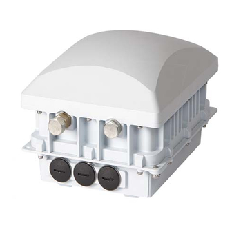
Ruckus Wireless ZoneFlex 7781CM Installation Manual
Dual band 802.11n strand-mount outdoor access point with integrated cable modem
Hide thumbs
Also See for ZoneFlex 7781CM:
- User manual (187 pages) ,
- Snmp reference manual (167 pages) ,
- Installation manual (52 pages)
Table of Contents
Advertisement
Quick Links
Download this manual
See also:
User Manual
Advertisement
Table of Contents

Related Manuals for Ruckus Wireless ZoneFlex 7781CM


Summary of Contents for Ruckus Wireless ZoneFlex 7781CM
-
Page 1: Installation Guide
™ ™ Ruckus Wireless ZoneFlex 7781CM Dual Band 802.11n Strand-Mount Outdoor Access Point with Integrated Cable Modem Installation Guide Part Number 800-70426-001 Rev B Published January 2013 www.ruckuswireless.com... - Page 3 Contents About This Installation Guide ..........1 Using this Installation Guide .
- Page 4 Administering the Cable Modem ......... 26 Viewing the SNMP Event Log .
- Page 5 Using the AP’s Web Interface to Switch LEDs to CM Mode ....50 Using an SNMP MIB to Switch LEDs to CM Mode ......51 Retrieving the CM’s MAC Address .
-
Page 7: About This Installation Guide
About This Installation Guide This Installation Guide provides information on how to set up the Ruckus Wireless ZoneFlex 7781CM Cable Modem Access Point (7781CM) on your network. Topics covered in this guide include basic configuration, operation and mounting. This guide is intended for use by those installing and configuring network equipment. -
Page 8: Using This Installation Guide
Figure 2 shows the main steps, and Table 1 includes the substeps. Figure 2. Adding a 7781CM to an existing Ruckus Wireless network flowchart Planning the Installation Preparing at the Depot and Sending to the Field Installing in the Field... - Page 9 About This Installation Guide Using this Installation Guide Table 1. Adding a 7781CM to an Existing Ruckus Wireless network Section Heading Planning the 7781CM Installation • 7781CM Versions • 7781CM Connectors • 7781CM LEDs • Reading the 7781CM LEDs • Powering Options •...
-
Page 10: Terms Used In This Guide
User Guide: Provides detailed information on how to configure the functions of the ■ unit. The User Guide is available for download on the Ruckus Wireless Support Web site at http://support.ruckuswireless.com/documents Release Notes: Provides late-breaking information about the current software release, ■... -
Page 11: Documentation Feedback
About This Installation Guide Documentation Feedback Documentation Feedback Ruckus Wireless is interested in improving its documentation and welcomes your comments and suggestions. You can email your comments to Ruckus Wireless at docs@ruckuswireless.com When contacting us, please include the following information: Document title ■... -
Page 12: Planning The 7781Cm Installation
Planning the 7781CM Installation 7781CM Versions Planning the 7781CM Installation Before installing the 7781CM, verify the version and plan the AP installation. 7781CM Versions ■ 7781CM Connectors ■ 7781CM LEDs ■ Powering Options ■ CM Heater ■ Positioning the GPS Antenna ■... - Page 13 Planning the 7781CM Installation 7781CM Versions Figure 4. Typical mesh elevation plane coverage, side view 7781-CM 7782 (RAP) (MAP) Excellent Excellent Reach Reach Excellent Reach...
-
Page 14: Cm Connectors
Planning the 7781CM Installation 7781CM Connectors 7781CM Connectors Figure 5 identifies the connectors on the 7781CM. Table 2 describes these connectors. Figure 5. 7781CM connectors Ethernet Port Earth Ground blanking cap Screw Reset Button blanking cap DC Connector blanking cap Coaxial Cable Connector B Table 2. -
Page 15: Cm Leds
Planning the 7781CM Installation 7781CM LEDs 7781CM LEDs Use the six LEDs to check the status of the access point and cable modem. Figure 6 identifies the LEDs on the 7781CM. Figure 6. 7781CM LEDs when the dome is pointing downwards BLUE Middle GREEN... -
Page 16: Reading Leds In Cable Modem Mode
Planning the 7781CM Installation Reading the 7781CM LEDs Reading LEDs in Cable Modem Mode In CM mode, the WHITE LED is always lit. Refer to Table 3 for a summary of CM mode LED behavior. Refer to CM Boot Sequence CM Online/Steady State for more details. - Page 17 Planning the 7781CM Installation Reading the 7781CM LEDs NOTE: The LEDs do not indicate whether the AP is in standalone mode or if ZoneDirector is managing the AP. To check if ZoneDirector is managing the access point, log into the ZoneDirector Web interface, go to the Access Points page, and then search for the access point’s MAC address.
-
Page 18: Powering Options
Planning the 7781CM Installation Powering Options Powering Options The 7781CM supports both DC power or AC power over cable (POC). Normally 12 VDC power is only used at the depot or when debugging. 45 to 90 VAC POC is only used when the 7781CM is mounted on a cable strand and powered via an F-type coaxial cable connected to the HFC cable plant. - Page 19 Planning the 7781CM Installation Positioning the GPS Antenna Figure 7. GPS Antenna Location under 7781CM Radome LED End Connector End Figure 8. 7781CM Dome-Down Mount GPS Antenna Position Keep Sky View Clear Connector End LED End...
-
Page 20: Performing A Site Survey
Performing a Site Survey Perform a site survey to determine the optimal 7781CM placement for maximum range, coverage, and network performance. Ruckus Wireless Support can supply Site Survey best practices information. The location and orientation that you choose for the 7781CM play a critical role in the performance of your wireless network. -
Page 21: Preparing The 7781Cm At The Depot And Shipping To The Field
Package Contents A complete ZoneFlex 7781CM package contains all of the items listed below: NOTE: The 7781CM comes assembled with the cable strand interface, which you will use to mount the assembly onto the cable strand. - Page 22 Preparing the 7781CM at the Depot and Shipping to the Field Unpacking the 7781CM One loop-and-eye safety cable ■ One M25 data cable gland ■ One hard line F connector-to-RG11 cable adapter ■ One green/yellow earth ground wire with ring terminal ■...
-
Page 23: Finding The Ap And Cm Mac Addresses
Preparing the 7781CM at the Depot and Shipping to the Field Finding the AP and CM MAC Addresses Finding the AP and CM MAC Addresses The 7781CM has separate MAC addresses for the internal AP and cable modem (CM). See Figure 9 for the location of the AP MAC address label. -
Page 24: Powering The 7781Cm With Dc
Powering the 7781CM with DC Powering the 7781CM with DC 1. Collect a customer-ordered 1.5A 12 VDC power supply, Ruckus Wireless part number 902-0169-xxyy (where xx = Country and yy = revision), which is designed to be used by a CCTV or similar application, and which includes a 2.5mm inner-diameter, 5.5mm... -
Page 25: Preparing The Administrative Computer
Preparing the 7781CM at the Depot and Shipping to the Field Preparing the Administrative Computer Preparing the Administrative Computer Use an administrative computer to configure basic operational parameters for the 7781CM access point and cable modem parts. NOTE: The following procedure is applicable if the administrative computer is running Windows 7 or Windows XP. - Page 26 Preparing the 7781CM at the Depot and Shipping to the Field Preparing the Administrative Computer Table 5. Configure your computer’s IP address settings 192.168.100.22, or any address in the 192.168.100.x network except: IP address • 192.168.100.1, which is the default IP address assigned to the CM, or •...
-
Page 27: Operating The Cm
Preparing the 7781CM at the Depot and Shipping to the Field Operating the CM Operating the CM In addition to the 7781CM AP command line interface (CLI) and web interface, the CM part of the 7781CM also has web and CLI interfaces. With these interfaces, you can operate the CM part. -
Page 28: Logging Into The Cm Web Interface Using A Dynamic Ip Address
Preparing the 7781CM at the Depot and Shipping to the Field Operating the CM 7. Click Log In. The Connection Status page appears, indicating that you have successfully logged on to the cable modem web interface. Continue with Viewing the Software Status. - Page 29 Preparing the 7781CM at the Depot and Shipping to the Field Operating the CM Figure 13. Software Status page There are two tables on the Software Status page – Information and Status. Table 6 Table 7 describes the information that these tables display. Table 6.
-
Page 30: Viewing The Connection Status
Preparing the 7781CM at the Depot and Shipping to the Field Operating the CM Viewing the Connection Status The Connection Status page displays information about the cable modem’s Hybrid Fiber Coax (HFC) and IP network connectivity, including its downstream and upstream channels and the IP address that is currently assigned to the cable modem. -
Page 31: Configuring The Downstream Frequency
Preparing the 7781CM at the Depot and Shipping to the Field Operating the CM Figure 15. Connection Status page - Page 2 of 2 Configuring the Downstream Frequency The Connection Status page allows you to set the downstream frequency for the cable modem. -
Page 32: Administering The Cable Modem
Figure 16. Security Status page 3. Ruckus Wireless recommends that you change the login and/or password as follows: a. Enter a new CM user ID in Password Change User ID. b. Enter a new CM user password in New Password. -
Page 33: Viewing The Snmp Event Log
Preparing the 7781CM at the Depot and Shipping to the Field Operating the CM 6. If you have made any changes on the Security Status page, then click Apply. If you have selected the Restore Factory Defaults Yes button, then the CM reboots and resets all CM parameters to the factory defaults. -
Page 34: Using Ssh To Set The Zonedirector Ip Address On The Ap
Using SSH to set the ZoneDirector IP Address on the AP Using SSH to set the ZoneDirector IP Address on the Ruckus Wireless strongly recommends that you configure, or stage, the AP part of the 7781CM before mounting it. It is more convenient to connect the administrative computer to the access point and configure the device in a depot than when the device is already mounted on the cable strand. - Page 35 Preparing the 7781CM at the Depot and Shipping to the Field Using SSH to set the ZoneDirector IP Address on the AP The following message appears, which indicates that you have assigned the ZoneDirector IP address: Please reboot for this change to take effect. 7.
-
Page 36: Configuring The Ap For Management By Flexmaster Or For Standalone Operation
Configuring the AP for Management by FlexMaster or for Standalone Operation Ruckus Wireless strongly recommends that you configure, or stage, the AP part of the 7781CM before mounting it. It is more convenient to connect the administrative computer to the access point and configure the device in a depot than when the device is already mounted on the cable strand. -
Page 37: Configuring Common Wireless Settings
Preparing the 7781CM at the Depot and Shipping to the Field Configuring the AP for Management by FlexMaster or for Standalone Operation Figure 18. The ZoneFlex Access Point login page 7. In User name, type super. 8. In Password, type sp-admin. 9. - Page 38 Preparing the 7781CM at the Depot and Shipping to the Field Configuring the AP for Management by FlexMaster or for Standalone Operation Figure 19. The Configuration > Radio 2.4 > Common tab 2. Verify that the common wireless settings are configured as listed in Table Table 8.
-
Page 39: Configuring Wireless # Settings
4. Clear the SSID box, and then type a unique and descriptive name that you want to call this wireless network. For example, you can type Ruckus Wireless AP. This SSID is the name that helps users identify this wireless network in their wireless network connection application. -
Page 40: Setting The Flexmaster Server Address (Optional)
Preparing the 7781CM at the Depot and Shipping to the Field Configuring the AP for Management by FlexMaster or for Standalone Operation NOTE: You can also configure other wireless settings on this and other Wireless # tabs (in addition to the settings described above), although it is not necessary for completing the AP installation. - Page 41 Preparing the 7781CM at the Depot and Shipping to the Field Configuring the AP for Management by FlexMaster or for Standalone Operation Figure 21. Type the FlexMaster server URL 3. Verify that the Auto option is selected. 4. In FlexMaster Server URL, type the URL of the FlexMaster server on the network. You can use either http or https to connect to the URL and include either the host name or IP address of the FlexMaster server in the URL.
-
Page 42: Verifying Ap Operation
Preparing the 7781CM at the Depot and Shipping to the Field Verifying AP Operation Verifying AP Operation Ruckus Wireless recommends that you verify that the 7781CM AP is operating correctly. NOTE: The cable modem and access point each has its own independent firmware load that is updated independently. -
Page 43: Associating A Wireless Client With The Ap
Preparing the 7781CM at the Depot and Shipping to the Field Verifying AP Operation Associating a Wireless Client with the AP 1. In the client device's wireless interface, select the SSID configured in “Configuring Wireless # Settings” on page 33. 2. -
Page 44: Disconnecting The Ap From The Power Source And Administrative Computer
Preparing the 7781CM at the Depot and Shipping to the Field Verifying AP Operation Disconnecting the AP from the Power Source and Administrative Computer 1. Disconnect the AP from the power source. 2. Verify that all LEDs are off. 3. Disconnect the Ethernet cable that runs to the AP’s RJ-45 Ethernet Port from your administrative computer. -
Page 45: Restoring The Administrative Computer's Network Settings
Preparing the 7781CM at the Depot and Shipping to the Field Shipping the 7781CM to the Field Restoring the Administrative Computer’s Network Settings If the administrative computer’s network settings were changed as described in “Preparing the Administrative Computer” on page 19 and you do not want to change the network settings back now, then continue with “Shipping the 7781CM to the Field”... -
Page 46: Installing The 7781Cm In The Field
Installing the 7781CM in the Field Installation Components and Constraints Installing the 7781CM in the Field Before installing the 7781CM, Ruckus Wireless recommends that you first complete the procedures described in “Planning the 7781CM Installation” on page 6 and “Preparing the 7781CM at the Depot and Shipping to the Field”... -
Page 47: Deploying The 7781Cm
Installing the 7781CM in the Field Deploying the 7781CM Deploying the 7781CM In this section, you will mount the 7781CM in its final mounting location. Perform the following: Mounting the 7781CM ■ Safety Cabling the 7781CM ■ Earth Grounding the 7781CM ■... -
Page 48: Earth Grounding The 7781Cm
Installing the 7781CM in the Field Deploying the 7781CM 2. Attach the safety cable eye end to the cable strand interface to any of the cable strand hanger bolts. Figure 23. Bolting the safety cable and the cable strand interface together Cable Strand Interface... -
Page 49: Installing The Cable Power Tap
RF signal on the coaxial cable, since the 7781CM Connector B is used for both electrical power and the RF signal. Ruckus Wireless recommends installing a cable power tap (Antronix MGT2000-SDPE tap, or equivalent) close to the 7781CM. Refer to the manufacturer’s instructions to mount the cable power tap on the coaxial cable. -
Page 50: Powering The 7781Cm With Poc
Installing the 7781CM in the Field Deploying the 7781CM Powering the 7781CM with POC The 7781CM supports both AC power over cable (POC) and DC power. 45 to 90 VAC POC is used when the 7781CM is mounted on a cable strand and powered via an F-type coaxial cable connected to the HFC cable plant. -
Page 51: Checking The Signal Level With An Rf Power Meter (Optional)
Installing the 7781CM in the Field Deploying the 7781CM Checking the Signal Level with an RF Power Meter (Optional) The 7781-CM cable modem is just like the standard DOCSIS 3.0 modem installed at home. 1. Connect an RF power meter to the cable from the cable power tap. 2. -
Page 52: Connecting And Sealing The Rj-45 Cable (Optional)
Installing the 7781CM in the Field Deploying the 7781CM Connecting and Sealing the RJ-45 Cable (Optional) The 7781CM comes with an RJ-45 waterproof connector for an optional customer-supplied ethernet cable for an external device, such as a security camera. If you are not using an optional RJ-45 ethernet cable from the 7781CM, then skip this procedure and continue with “Mounting the 7781CM”... -
Page 53: Verifying Cm And Ap Operation
Verifying CM and AP Operation Verifying CM and AP Operation After deploying the 7781CM on the cable strand, Ruckus Wireless strongly recommends that you verify that the CM and AP are operating correctly: Logging Into the CM’s Web Interface via CMTS ■... -
Page 54: Logging Into The Ap's Web Interface Via Cmts
Installing the 7781CM in the Field Verifying CM and AP Operation Logging Into the AP’s Web Interface via CMTS 1. Obtain the IP address that is assigned to the AP. You can obtain this information from the DHCP server at the CMTS. 2. -
Page 55: Operating And Troubleshooting The 7781Cm
Operating and Troubleshooting the 7781CM Switching LEDs to CM Mode Operating and Troubleshooting the 7781CM This section lists some information that may be useful in operating and troubleshooting the 7781CM. Topics discussed include: Switching LEDs to CM Mode ■ Retrieving the CM’s MAC Address ■... -
Page 56: Using The Ap's Web Interface To Switch Leds To Cm Mode
Operating and Troubleshooting the 7781CM Switching LEDs to CM Mode Using the AP’s Web Interface to Switch LEDs to CM Mode This procedure is only available if the AP is in standalone mode. 1. Log in to the AP’s Web interface as described in “Logging Into the AP’s Web Interface via CMTS”... -
Page 57: Using An Snmp Mib To Switch Leds To Cm Mode
Use SNMP via the CMTS to set MIB values on the 7781CM that control the LED mode. NOTE: Before starting this procedure, you must first obtain the related MIBs from Ruckus Wireless. Contact your authorized Ruckus Wireless sales representative or Ruckus Wireless Support. Visit http://support.ruckuswireless.com/contacts for Ruckus Wireless Support contact information. -
Page 58: Retrieving The Cm's Mac Address Using The Cm Cli
Operating and Troubleshooting the 7781CM Retrieving the CM’s MAC Address Retrieving the CM’s MAC Address using the CM CLI Use CM command line interface via the CMTS to retrieve the CM’s MAC address. 1. Obtain the IP address assigned to the CM. You can obtain this information from the DHCP server at the CMTS. -
Page 59: Rebooting And Resetting The 7781Cm
Operating and Troubleshooting the 7781CM Rebooting and Resetting the 7781CM Rebooting and Resetting the 7781CM Refer to “Appendix B: Rebooting and Resetting the 7781CM” on page 58 for instructions on rebooting and resetting the AP and CM parts of the 7781CM. How Radio Frequency Scanning Works The 7781CM performs radio frequency scanning differently, depending on the 7781CM model and the DOCSIS standard with which it is compliant (either DOCSIS, EuroDOCSIS... -
Page 60: Japan Docsis-Compliant 7781Cm
Operating and Troubleshooting the 7781CM How Radio Frequency Scanning Works NOTE: EuroDOCSIS generic channel scanning is required the first time the 7781CM connects to an MSO. After the initial scan, the 7781CM can retrieve the local country frequency plan during its normal operation. Japan DOCSIS-Compliant 7781CM The following steps describe how a Japan DOCSIS-compliant 7781CM performs radio frequency scanning:... -
Page 61: Changing The Administrative Password
Configuring Advanced Settings and Features The AP has been configured for basic operation. However, the Ruckus Wireless AP supports many advanced settings and features. Refer to the ZoneFlex Outdoor Access Point User Guide, ZoneDirector User Guide, or FlexMaster User Guide for instructions on how to configure the advanced setting and feature parameters. - Page 62 What to Do Next Reading Related Documentation...
-
Page 63: Appendix A: Factory-Supplied And Customer-Ordered Parts
Appendix A: Factory-Supplied and Customer- Ordered Parts Table 11. Factory-supplied and customer-supplied parts Part Ruckus 7781CM Kit or Notes Wireless Customer Ordered RJ-45 waterproof cable 700-60229- 7781CM kit Cable gland base gland Clamping ring assembly (1 each) Rubber O-ring Sealing nut Hard line-to-RG11 760-66201- 7781CM kit... -
Page 64: Appendix B: Rebooting And Resetting The 7781Cm
Appendix B: Rebooting and Resetting the 7781CM Appendix B: Rebooting and Resetting the 7781CM Rebooting and Resetting the AP and CM ■ Resetting the CM to Factory Default Settings ■ Rebooting and Resetting the AP and CM CAUTION: Performing this procedure resets the AP and CM parts of the 7781CM to their factory default settings. -
Page 65: Remotely Rebooting The Ap
AP and CM. Remotely Rebooting the AP NOTE: The AP part of the 7781CM can be remotely rebooted, but Ruckus Wireless does not recommend that the CM be remotely rebooted, as the AP communicates with the administrative computer through the CM. -
Page 66: Resetting The Cm To Factory Default Settings
The procedure is the same, regardless whether you perform this operation from the AP or CM. NOTE: Before starting this procedure, you must first obtain the related MIBs from Ruckus Wireless. Contact your authorized Ruckus Wireless sales representative or Ruckus Wireless Support. Visit http://support.ruckuswireless.com/contacts for Ruckus Wireless Support contact information. - Page 67 Appendix B: Rebooting and Resetting the 7781CM...
- Page 68 Copyright © 2006-2013. Ruckus Wireless, Inc. 350 West Java Dr. Sunnyvale, CA 94089. USA www.ruckuswireless.com...
Need help?
Do you have a question about the ZoneFlex 7781CM and is the answer not in the manual?
Questions and answers