Table of Contents
Advertisement
Quick Links
Advertisement
Table of Contents

Related Manuals for Arbor Technology ITX-i89H0


Summary of Contents for Arbor Technology ITX-i89H0
- Page 1 ITX-i89H0 Mini-ITX Industrial Motherboard User’s Manual Version 1.0 2016.05...
- Page 2 This page is intentionally left blank. - II -...
-
Page 3: Revision History
Revision History Version Release Time Description May, 2016 Initial release - i -... -
Page 4: Table Of Contents
Contents Table of Contents Revision History .................i Table of Contents ................ii Preface....................iv Copyright Notice ..................iv Declaration of Conformity ..............iv CE ....................iv FCC Class A ..................v RoHS ....................v SVHC / REACH ................vi Warning ....................vi Replacing Lithium Battery .............. - Page 5 Contents 3.2.9. S5 RTC Wake Settings ............45 3.2.10. CSM Configuration ............46 3.3. Chipset ................... 47 3.3.1. Graphics Configuration ............48 3.3.2. PEG Port Configuration ............48 3.3.3 Memory Configuration ............49 3.3.4. LCD Control ................. 49 3.3.5 PCI Express Configuration ........... 50 3.3.6 USB Configuration ..............
-
Page 6: Preface
Preface Preface Copyright Notice All Rights Reserved. The information in this document is subject to change without prior notice in order to improve the reliability, design and function. It does not represent a commitment on the part of the manufacturer. Under no circumstances will the manufacturer be liable for any direct, indirect, special, incidental, or consequential damages arising from the use or inability to use the product or documentation, even if advised of the possibility of such... -
Page 7: Fcc Class A
(PBDE) in electrical and electronic products. Member states of the EU are to enforce by 7/1/2006. ARBOR Technology Corp. hereby states that the listed products do not contain unintentional additions of lead, mercury, hex chrome, PBB or PBDB that exceed a maximum concentration value of 0.1% by weight or for cadmium exceed... -
Page 8: Svhc / Reach
Preface SVHC / REACH To minimize the environmental impact and take more responsibility to the earth we live, Arbor hereby confirms all products comply with the restriction of SVHC (Substances of Very High Concern) in (EC) 1907/2006 (REACH --Registration, Evaluation, Authorization, and Restriction of Chemicals) regulated by the European Union. -
Page 9: Warranty
Preface Warranty This product is warranted to be in good working order for a period of two years from the date of purchase. Should this product fail to be in good working order at any time during this period, we will, at our option, replace or repair it at no additional charge except as set forth in the following terms. - Page 10 This page is intentionally left blank.
-
Page 11: Chapter 1 Introduction
Chapter 1 Introduction Chapter 1 - Introduction - 1 -... -
Page 12: Product Highlights
Introduction 1.1. Product Highlights • Soldered onboard 6th Generation Intel® Core™/Xeon® Processor • Integrated Gigabit Ethernet • ECC memory support • Dual DisplayPorts and one HDMI support • Extended operating temp: -20~70ºC 1.2. About this Manual This manual is intended for experienced users and integrators with hardware knowledge of computers. -
Page 13: Specifications
Introduction 1.3. Specifications Mini-ITX industrial motherboard Form Factor ® Soldered onboard Intel Core™ i3-6100E Dual-core 2.7GHz (Base) ® ® Intel Xeon Processor E3-1505L V5 Quad-core 2.0GHz (Base) / 2.8GHz Processor (Trubo) ® ® Intel Xeon Processor E3-1515M V5 Quad-core 2.8GHz (Base) / 3.7GHz (Trubo)(Optional) Chipset ®... -
Page 14: Inside The Package
Introduction 1.4. Inside the Package Before starting to install the single board, make sure the following items are shipped: 1 x ITX-i89H0 Mini-ITX industrial motherboard 1 x Cooler 1 x Driver CD 1 x Quick Installation Guide If any of the aforelisted items is damaged or missing, contact your vendor immediately. -
Page 15: Ram Installation
Introduction 1.6. RAM Installation The main board has one memory module (SO-DIMM) sockets. Load the computer with a memory module of higher capacity to make programs run faster. The memory module for the computer’s SO-DIMM socket should be a DDR3L with a “key notch”... - Page 16 This page is intentionally left blank. - 6 -...
-
Page 17: Chapter 2 Getting Started
Chapter 2 Getting Started Chapter 2 - Getting Started - 7 -... -
Page 18: Board Dimensions
Getting Started 2.1. Board Dimensions 6.17 163.65 33.1 57.9 85.8 111.76 135.65 156.5 Unit: mm - 8 -... -
Page 19: Block Diagram
Getting Started 2.2. Block Diagram DCIN1 DDI-1 HDMI1 +12 DC Brick Intel ® HDMI conn. SKYLAKE DDI-2 2 x DDR4 DDR4 - 2133MHz SO-DIMM socket Double Stacked Processor DP Connector DDI-3 PCIe Gen3 x 16 x16PCEG1 (x4) SATA0 USB 2.0 port WIFI1 SSD1 E-key Socket... -
Page 20: Jumpers & Connectors
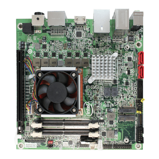
Getting Started 2.3. Jumpers & Connectors The board comes with some connectors to join some devices and also some jumpers to alter the hardware configuration. The following in this chapter will explicate each of these components one-by-one. 2.3.1. Layout This section will provide an overview of this board. ⑭... -
Page 21: Jumpers
Getting Started 2.3.2. Jumpers ❶ JPCH1 Function: Clear CMOS Selection Setting: Jumper Type: 2.54mm pitch 1x2-pin headers Mode Short Clear CMOS Open Keep CMOS (default) Board Top ⑭ PWROUT1 ⑬ SYSFAN1 ➍ ⑫ ⑯ ⑮ JLCD1 LPC1 USB3 ⑰ JCOM1 ⑱... - Page 22 Getting Started ❷ JME1 Function: ME Selection Setting: Jumper Type: 2.54mm pitch 1×2-pin headers Mode Short ME Disable Open ME Enable (default) Board Top ⑭ PWROUT1 ⑬ SYSFAN1 ➍ ⑫ ⑯ ⑮ JLCD1 LPC1 USB3 ⑰ JCOM1 ⑱ WIFI1 ⑪ X16PCEG1 ⑲...
- Page 23 Getting Started ❸ JME2 Function: SRTC Reset Selection Setting: Jumper Type: 2.54mm pitch 1x2-pin headers Mode Short Clear ME RTC Open Normal (default) Board Top ⑭ PWROUT1 ⑬ SYSFAN1 ➍ ⑫ ⑯ ⑮ JLCD1 LPC1 USB3 ⑰ JCOM1 ⑱ WIFI1 ⑪...
- Page 24 Getting Started ❹ JLCD1 Function: LCD Panel Voltage Selection Setting: Jumper Type: 2.54mm pitch 1x3-pin headers Mode 1-2 +5V 2-3 +3.3V (Default) Board Top ⑭ PWROUT1 ⑬ SYSFAN1 ➍ ⑫ ⑯ ⑮ JLCD1 LPC1 USB3 ⑰ JCOM1 ⑱ WIFI1 ⑪ X16PCEG1 ⑲...
-
Page 25: Connectors
Getting Started 2.3.3. Connectors ① USB2: USB3.0/2.0 Connector Function: Pin Assignment: USB3.0/2.0 Connector Connector Type: 2x10 pin box header Pin Desc. Pin Desc. 20 N/C 1 +V5S 19 +V5S 2 USB3_RXN5_C 18 USB3_RXN6_C 3 USB3_RXP5_C 17 USB3_RXP6_C 4 GND 16 GND 5 USB3_TXN5_C 15 USB3_TXN6_C 6 USB3_TXP5_C... - Page 26 Getting Started ②③ SATA1~2 Function: Serial ATA Connector Pin Assignment: Connector Type: Serial ATA Connector The pin assignments conform to the industry standard. Board Top ⑭ PWROUT1 ⑬ SYSFAN1 ➍ ⑫ ⑯ ⑮ JLCD1 LPC1 USB3 ⑰ JCOM1 ⑱ WIFI1 ⑪...
- Page 27 Getting Started ④ AUDIO1 Function: Audio connector Pin Assignment: Connector Type: Double-stacked ø3.5mm Description stereo audio jacks Line out Line-out Mic-in Board Top ⑭ PWROUT1 ⑬ SYSFAN1 ➍ ⑫ ⑯ ⑮ JLCD1 LPC1 USB3 ⑰ JCOM1 ⑱ WIFI1 ⑪ X16PCEG1 ⑲...
- Page 28 Getting Started ⑤ USB1 Function: USB 3.0/2.0 Stack Pin Assignment: Connectors Connector Type: Quadruple-stacked USB The pin assignments conform to connectors the industry standard. Board Top ⑭ PWROUT1 ⑬ SYSFAN1 ➍ ⑫ ⑯ ⑮ JLCD1 LPC1 USB3 ⑰ JCOM1 ⑱ WIFI1 ⑪...
- Page 29 Getting Started ⑥ LAN1 Function: RJ-45 LAN and USB 2.0 Stack Pin Assignment: Connectors Connector Type: RJ-45 and double-stacked USB The pin assignments conform connectors to the industry standard. Board Top ⑭ PWROUT1 ⑬ SYSFAN1 ➍ ⑫ ⑯ ⑮ JLCD1 LPC1 USB3 ⑰...
- Page 30 Getting Started ⑦ HDMI1 Function: HDMI Connector Pin Assignment: Connector Type: 19-pin HDMI connector The pin assignments conform to the industry standard. Board Top ⑭ PWROUT1 ⑬ SYSFAN1 ➍ ⑫ ⑯ ⑮ JLCD1 LPC1 USB3 ⑰ JCOM1 ⑱ WIFI1 ⑪ X16PCEG1 ⑲...
- Page 31 Getting Started ⑧ Function: DisplayPort Stack Connectors Pin Assignment: Connector Type: Double-stacked DisplayPort The pin assignments connectors conform to the industry standard. Board Top ⑭ PWROUT1 ⑬ SYSFAN1 ➍ ⑫ ⑯ ⑮ JLCD1 LPC1 USB3 ⑰ JCOM1 ⑱ WIFI1 ⑪ X16PCEG1 ⑲...
- Page 32 Getting Started ⑨ DCIN1 Function: DC IN Jack Pin Assignment: Connector Type: 4-pin DC in Jack Pin Desc. Pin Desc. 2 VCC1 1 GND1 4 VCC2 3 GND2 Board Top ⑭ PWROUT1 ⑬ SYSFAN1 ➍ ⑫ ⑯ ⑮ JLCD1 LPC1 USB3 ⑰...
- Page 33 Getting Started ⑩⑬ CPUFAN1&SYSFAN1 Function: Fan Power Connector Pin Assignment: Connector Type: 2.54mm pitch 1x4-pin Pin Description one-wall connector 1 GND 2 +12V 3 RPM 4 Control Board Top ⑭ PWROUT1 ⑬ SYSFAN1 ➍ ⑫ ⑯ ⑮ JLCD1 LPC1 USB3 ⑰...
- Page 34 Getting Started ⑪ X16PCEG1 Function: PCIex16 Gen 3.0 slot Pin Assignment: The pin assignments conform to the industry standard. Board Top ⑭ PWROUT1 ⑬ SYSFAN1 ➍ ⑫ ⑯ ⑮ JLCD1 LPC1 USB3 ⑰ JCOM1 ⑱ WIFI1 ⑪ X16PCEG1 ⑲ SSD1 ⑩...
- Page 35 Getting Started ⑫ Function: Front panel LED & audio Pin Assignment: header Connector Type: 2.54mm pitch 2x5-pin headers Pin Desc. Pin Desc. 1 HLED+ 2 PLED+ 3 HLED- 4 PLED- 5 RESET+ 6 PSON+ 7 RESET- 8 PSON- 9 +5V 10 N/C Board Top ⑭...
- Page 36 Getting Started ⑭ PWROUT1 Function: SATA Power Connector Pin Assignment: Connector Type: Onboard 4-pin box connector Pin Desc. 1 5V 2 GND 3 GND 4 12V Board Top ⑭ PWROUT1 ⑬ SYSFAN1 ➍ ⑫ ⑯ ⑮ JLCD1 LPC1 USB3 ⑰ JCOM1 ⑱...
- Page 37 Getting Started ⑮ USB3 Function: USB 2.0 Connector Pin Assignment: Connector Type: 2.54mm pitch 2x5-pin Pin Desc. Pin Desc. headers 1 +5VS 2 +5VS 3 USBP7N 4 USBP8N 5 USBP7P 6 USBP8P 7 GND 8 GND 9 N/C 10 GND Board Top ⑭...
- Page 38 Getting Started ⑯ LPC1 Function: Low Pin Count Connector Pin Assignment: Connector 2x10-pin 2.54mm pitch Pin Desc. Pin Desc. Type: male pin header CLK_PC_24M L_FRAME# PLTRST# +V5S L_AD3 L_AD2 +V3.3S L_AD1 L_AD0 SMBCLK_M SMBDATA_M +V3.3A SER_IRQ TPM_CLKRUN# LPCPD#_LPC L_DRQ_N Board Top ⑭...
- Page 39 Getting Started ⑰ JCOM1 Function: UART Connector Pin Assignment: Connector 2.54mm pitch 2x5 pin box header Pin Desc. Pin Desc. Type: 1 N/C 2 RXD 3 TXD 4 N/C 5 GND 10 N/C Board Top ⑭ PWROUT1 ⑬ SYSFAN1 ➍ ⑫...
- Page 40 Getting Started ⑱ WIFI1 Function: NGFF M.2 E-Key Socket for WIFI Pin Assignment: The pin assignments conform to the industry standard. Board Top ⑭ PWROUT1 ⑬ SYSFAN1 ➍ ⑫ ⑯ ⑮ JLCD1 LPC1 USB3 ⑰ JCOM1 ⑱ WIFI1 ⑪ X16PCEG1 ⑲...
- Page 41 Getting Started ⑲ SSD1 Function: NGFF M.2 M-Key Socket for SSD Pin Assignment: The pin assignments conform to the industry standard. Board Top ⑭ PWROUT1 ⑬ SYSFAN1 ➍ ⑫ ⑯ ⑮ JLCD1 LPC1 USB3 ⑰ JCOM1 ⑱ WIFI1 ⑪ X16PCEG1 ⑲...
-
Page 42: Driver Installation Notes
Getting Started 2.4. Driver Installation Notes The board supports Windows 8.1 and Windows 10. Find the necessary drivers on the CD that comes with your purchase. For different OS, the driver/utility installation may vary slightly, but generally they are similar. Find the drivers on CD by the following paths: Windows 8.1 &... -
Page 43: Chapter 3 - Bios
Chapter 3 BIOS Chapter 3 - BIOS - 33 -... - Page 44 BIOS The BIOS Setup utility is featured by AMI BIOS to configure the system settings stored in the system’s BIOS ROM. AMI BIOS is activated once the computer powers on. After entering the utility, use the left/right arrow keys to navigate between the top menus and use the down arrow key to access one.
-
Page 45: Main
Aptio Setup Utility - Copyright (C) 2016 American Megatrends, Inc. Advanced Chipset Security Boot Save & Exit Main Set the Date. Use Tab to Switch BIOS Name ITX-i89H0 between Date elements. BIOS Version 1.05 Build Data and Time 03/29/2016 18:55:17 Access Level Administator... -
Page 46: Advanced
BIOS 3.2. Advanced The Advanced menu controls the system’s CPU, ACP I, Super IO, SATA and USB, etc... It also helps users monitor hardware health. Aptio Setup Utility - Copyright (C) 2016 American Megatrends, Inc. Main Advanced Chipset Security Boot Save &... -
Page 47: Cpu Configuration
BIOS 3.2.1. CPU Configuration Access this submenu to setup the CPU Configuration. Aptio Setup Utility - Copyright (C) 2016 American Megatrends, Inc. Advanced CPU Configuration Enabled for Windows XP Intel(R) Core(TM) i3-6100E CPU @ 2.70GHz and Linux (OS CPU Signature optimized for Hyper- 506E3 Microcode Patch... -
Page 48: Pci Subsystem Settings
BIOS Enables/disables the SpeedStep. Intel(R) SpeedStep(tm) Enabled is the default. Enables/disables the CPU C states. CPU C states Enabled is the default. Enables/disables the Enhanced C-states. Enhanced C-states Enabled is the default. Sets the package C state limit. Package C State limit AUTO is the default. -
Page 49: Sata Configuration
BIOS 3.2.3. SATA Configuration SATA Configuration manages the system’s SATA configuration and also delivers its status. Aptio Setup Utility - Copyright (C) 2016 American Megatrends, Inc. Advanced Enable or disable SATA Device. SATA Controller(s) [Enabled] SATA Mode Selection [AHCI] Serial ATA SSD1 Empty Port [Enabled]... -
Page 50: Acpi Settings
BIOS 3.2.4. ACPI Settings USB Configuration displays the status of USB connection and configures USB parameters. Aptio Setup Utility - Copyright (C) 2012 American Megatrends, Inc. Aptio Setup Utility - Copyright (C) 2016 American Megatrends, Inc. Advanced ACPI Settings Select ACPI sleep state the system will Enable Hibernation [Enabled]... -
Page 51: Usb Configuration
BIOS 3.2.5. USB Configuration USB Configuration displays the status of USB connection and configures USB parameters. Aptio Setup Utility - Copyright (C) 2016 American Megatrends, Inc. Advanced USB Configuration Enables Legacy USB support. AUTO option disables legacy USB Module Version support if no USB devices are connected. -
Page 52: Amt Configuration
BIOS 3.2.6. AMT Configuration Access this submenu to setup the AMT Configuration Aptio Setup Utility - Copyright (C) 2015 American Megatrends, Inc. Advanced Enable/Disable Intel(R) Active [Enabled] Intel AMT Management Technology BIOS Extension. Note : iAMT H/W is always enabled. This option just controls the BIOS extension execution. -
Page 53: Super Io Configuration
BIOS 3.2.7. Super IO Configuration Access this submenu to setup the Super IO Configuration Aptio Setup Utility - Copyright (C) 2016 American Megatrends, Inc. Advanced Set Parameters of Serial Port F81801 Super IO Configuration 1 (COMA) Super IO Chip NCT6776 Serial Port 1 Configuration Restore AC Power Loss [Power Off]... -
Page 54: Hardware Monitor
BIOS 3.2.8. Hardware Monitor Access this submenu to monitor of the overall inboard hardware health events, such as System temperature, CPU voltage, CPU & System fan speed... etc. Aptio Setup Utility - Copyright (C) 2016 American Megatrends, Inc. Advanced PC Health Status CPU Temperature Fan1 Speed Fan2 Speed... -
Page 55: S5 Rtc Wake Settings
BIOS 3.2.9. S5 RTC Wake Settings Access this submenu to setup S5 RTC Wake Setting Aptio Setup Utility - Copyright (C) 2016 American Megatrends, Inc. Advanced Enables or disables [Disabled] Wake system from S5 system wake on alarm event. Select FixedTime, system will wake on the hr::min::sec specified. -
Page 56: Csm Configuration
BIOS 3.2.10. CSM Configuration Access this submenu to setup CSM Configuration Aptio Setup Utility - Copyright (C) 2016 American Megatrends, Inc. Advanced Compatibility Support Module Configuration Enable/Disable CSM Support. [Enabled] CSM Support CSM16 Module Version 07.77 Boot option filter [UEFI and Legacy] Option ROM execution [Do not lauch] Network... -
Page 57: Chipset
BIOS 3.3. Chipset Access this Chipset menu to configure the system’s chipset. Aptio Setup Utility - Copyright (C) 2016 American Megatrends, Inc. Main Advanced Security Boot Save & Exit Chipset VT-d [Enabled] VT-d capability Above 4GB MMIO assigment [Disabled] PCH-IO Configuration Graphics Configuration PEG Port Configuration Memory Configuration... -
Page 58: Graphics Configuration
BIOS 3.3.1. Graphics Configuration Access this submenu to configure Graphics Configuration. The featured settings are: Setting Description Graphics Turbo IMON Sets the graphics turbo IMON current values. ► Options available are 14 to 31(default). Current Set IGD or PCI graphic device as the Primary Display. Primary Display ►... -
Page 59: Memory Configuration
BIOS 3.3.3 Memory Configuration Aptio Setup Utility - Copyright (C) 2016 American Megatrends, Inc. Chipset Memory Information Memory RC Version 1.0.0.1 Memory Frequency 2133 Mhz Total Memory 8192 MB 1200 DIMM#0 8192 MB DIMM#1 Not Present DIMM#2 Not Present DIMM#3 Not Present Memory Timings (tCL-tRCD-tRP-tRAS) 15-36... -
Page 60: Pci Express Configuration
BIOS 3.3.5 PCI Express Configuration Access this submenu to configure WIFI Configuration. Setting Description WIFI Port Settings Setting Description Enable and Disable WIFI Port WIFI 1 ► Enabled is the default. WIFI1 Set the ASPM Level ► ASPM Support Option: Disabled(default), L0s, L1, L0sL1, Auto. -
Page 61: Pch Lan Configuration
BIOS 3.3.8 PCH LAN Configuration Access this submenu to configure PCH LAN Configuration. Setting Description Enable and Disable onboard NIC PCH LAN Controller ► Enabled is the default. Enable and Disable Wake on LAN Wake on LAN ► Enabled is the default. - 51 -... -
Page 62: Security
BIOS 3.4. Security The Security menu sets up the administrator password. Once an administrator password is set up, this BIOS Setup utility is limited to access and will ask for the password each time any access is attempted. Aptio Setup Utility - Copyright (C) 2016 American Megatrends, Inc. Main Advanced Chipset Boot... -
Page 63: Boot
BIOS 3.5. Boot Access this menu to change system boot settings. Aptio Setup Utility - Copyright (C) 2016 American Megatrends, Inc. Main Advanced Chipset Security Save & Exit Boot Number of seconds to wait for Boot Configuration setup activation key. Setup Prompt Timeout 65535 (0xFFFF) means indefinite Bootup Numlock State... - Page 64 BIOS 3.6. Save & Exit The Exit menu features a handful of commands to launch actions from the BIOS Setup utility regarding saving changes, quitting the utility and recovering defaults. Aptio Setup Utility - Copyright (C) 2016 American Megatrends, Inc. Main Advanced Chipset Security...
-
Page 65: Appendices
Appendices Appendices - 55 -... -
Page 66: Appendix A. I/O Port Address Map
Appendices Appendix A. I/O Port Address Map Each peripheral device in the system is assigned a set of I/O port addresses which also becomes the identity of the device. The following table lists the I/O port addresses used. Address Device Description 0x0000F080-0x0000F087 Microsoft Basic Display Adapter 0x000003B0-0x000003BB... -
Page 67: Device Description
Appendices Address Device Description 0x0000002C-0x0000002D Programmable interrupt controller 0x00000030-0x00000031 Programmable interrupt controller 0x00000034-0x00000035 Programmable interrupt controller 0x00000038-0x00000039 Programmable interrupt controller 0x0000003C-0x0000003D Programmable interrupt controller 0x000000A0-0x000000A1 Programmable interrupt controller 0x000000A4-0x000000A5 Programmable interrupt controller 0x000000A8-0x000000A9 Programmable interrupt controller 0x000000AC-0x000000AD Programmable interrupt controller 0x000000B0-0x000000B1 Programmable interrupt controller 0x000000B4-0x000000B5... -
Page 68: Appendix B. Interrupt Request Lines (Irq)
Appendices Appendix B. Interrupt Request Lines (IRQ) Peripheral devices use interrupt request lines to notify CPU for the service required. The following table shows the IRQ used by the devices on board. Level Function IRQ0 System timer IRQ4 SM Bus Controller IRQ8 High Precision Event Timer IRQ16... -
Page 69: Appendix C. Bios Memory Map
Appendices Appendix C. BIOS Memory Map Address Device Description 0xD0716000-0xD07167FF Standard SATA AHCI Controller 0xE0000000-0xEFFFFFFF Motherboard resources 0xFED01000-0xFED01FFF Motherboard resources 0xFED03000-0xFED03FFF Motherboard resources 0xFED04000-0xFED04FFF Motherboard resources 0xFED0C000-0xFED0FFFF Motherboard resources 0xFED08000-0xFED08FFF Motherboard resources 0xFED1C000-0xFED1CFFF Motherboard resources 0xFEE00000-0xFEEFFFFF Motherboard resources 0xFEF00000-0xFEFFFFFF Motherboard resources 0xD0000000-0xD03FFFFF Microsoft Basic Display Adapter 0xC0000000-0xCFFFFFFF... -
Page 70: Appendix D: Watchdog Timer (Wdt) Setting
Appendices Appendix D: Watchdog Timer (WDT) Setting WDT is widely used for industry application to monitor the activity of CPU. Ap- plication software depends on its requirement to trigger WDT with adequate timer setting. Before WDT time out, the functional normal system will reload the WDT. - Page 71 Appendices delay(DELAY_TIME); /* Watchdog Timer Control Register */ SMB_Byte_WRITE(SMB_PORT_AD,SMB_DEVICE_ADD,0x36,0x72); int WDT_Count(void) int iData; /* Watchdog Timer Range Register */ iData = SMB_Byte_READ(SMB_PORT_AD,SMB_DEVICE_ADD,0x37); return iData; void WDT_Clear(int iCount) /* Watchdog Timer Range Register */ SMB_Byte_WRITE(SMB_PORT_AD,SMB_DEVICE_ADD,0x37,iCount); void WDT_Stop(void) /* Watchdog Timer Control Register */ SMB_Byte_WRITE(SMB_PORT_AD,SMB_DEVICE_ADD,0x36,0x52); - 61 -...
Need help?
Do you have a question about the ITX-i89H0 and is the answer not in the manual?
Questions and answers