Table of Contents
Advertisement
Quick Links
Advertisement
Table of Contents

Related Manuals for Arbor Technology ITX-i2203


Summary of Contents for Arbor Technology ITX-i2203
- Page 1 ITX-i2203 Mini-ITX Industrial Motherboard User’s Manual Version 1.2 2020.04...
- Page 2 This page is intentionally left blank. - II -...
- Page 3 Revision History Version Release Time Description Aug, 2016 Initial release Jun, 2017 Update “A.2 BIOS Update using ACT Utility” Apr, 2020 Added “OEM request” to SIM socket - i -...
-
Page 4: Table Of Contents
Contents Table of Contents Revision History .................i Table of Contents ................ii Preface....................iv Copyright Notice ..................iv Declaration of Conformity ..............iv CE ....................iv FCC Class A ..................v RoHS ....................v SVHC / REACH ................vi Warning ....................vi Replacing Lithium Battery .............. - Page 5 Contents 3.2.9. S5 RTC Wake Settings ............51 3.2.10. CSM Configuration ............52 3.2.11. SDIO Configuration ............53 3.3. Chipset ................... 54 3.3.1. North Bridge ................. 55 3.3.2. South Bridge ................ 58 3.4. Security ..................60 3.5. Boot ....................61 3.6.
-
Page 6: Preface
Preface Preface Copyright Notice All Rights Reserved. The information in this document is subject to change without prior notice in order to improve the reliability, design and function. It does not represent a commitment on the part of the manufacturer. Under no circumstances will the manufacturer be liable for any direct, indirect, special, incidental, or consequential damages arising from the use or inability to use the product or documentation, even if advised of the possibility of such... -
Page 7: Fcc Class A
(PBDE) in electrical and electronic products. Member states of the EU are to enforce by 7/1/2006. ARBOR Technology Corp. hereby states that the listed products do not contain unintentional additions of lead, mercury, hex chrome, PBB or PBDB that exceed a maximum concentration value of 0.1% by weight or for cadmium exceed... -
Page 8: Svhc / Reach
Preface SVHC / REACH To minimize the environmental impact and take more responsibility to the earth we live, Arbor hereby confirms all products comply with the restriction of SVHC (Substances of Very High Concern) in (EC) 1907/2006 (REACH --Registration, Evaluation, Authorization, and Restriction of Chemicals) regulated by the European Union. -
Page 9: Warranty
Preface Warranty This product is warranted to be in good working order for a period of two years from the date of purchase. Should this product fail to be in good working order at any time during this period, we will, at our option, replace or repair it at no additional charge except as set forth in the following terms. - Page 10 This page is intentionally left blank.
-
Page 11: Chapter 1 Introduction
Chapter 1 Introduction Chapter 1 - Introduction - 1 -... -
Page 12: Product Highlights
Introduction 1.1. Product Highlights • Low profile design • Soldered onboard Intel Celeron Processor N3160 ® ® • Dual Gigabit Ethernet ports • 2 x HDMI ports, dual Channel 24-bit LVDS • Dual independent displays supported • Anti-Crash Technology (ACT) for automatical system BIOS recovering 1.2. -
Page 13: Specifications
Introduction 1.3. Specifications ® ® Processor Soldered onboard Intel Celeron Processor N3160 1.6GHz 1 x DDR3L SO-DIMM socket, supporting up to 8GB Memory 1333/1600MT/s SDRAM BIOS AMI BIOS Watchdog Timer 1~255 levels reset Super I/O Fintek F81801 Serial Port 1 x Serial Port, RS-232/422/485 selectable 6-pin wafer connector for PS/2 keyboard/ mouse Keyboard &... -
Page 14: Inside The Package
Introduction 1.4. Inside the Package Before starting to install the single board, make sure the following items are shipped: 1 x ITX-i2203 Industrial Motherboard w/ Heatsink 1 x Driver CD 1 x Quick Installation Guide If any of the aforelisted items is damaged or missing, contact your vendor immediately. -
Page 15: Ram Installation
Introduction 1.6. RAM Installation The main board has one memory module (SO-DIMM) sockets. Load the computer with a memory module of higher capacity to make programs run faster. The memory module for the computer’s SO-DIMM socket should be a DDR3L with a “key notch”... - Page 16 This page is intentionally left blank. - 6 -...
-
Page 17: Chapter 2 Getting Started
Chapter 2 Getting Started Chapter 2 - Getting Started - 7 -... -
Page 18: Board Dimensions
Getting Started 2.1. Board Dimensions Heat sink(16.5) 5.3mm 6.33 157.48 127,5 18,5 107,07 40,07 17,2 Unit:mm - 8 -... -
Page 19: Block Diagram
Getting Started 2.2. Block Diagram Board Block Diagram +24V DC input LVDS1 DDI0 Dual channels 24-bit LVDS PWR1, PTN3460BS ACES 87209-304*-06 ATX-. R/A PWR2, DC-jack connector Asmedia HDMI1 DDI1 HDMI ASM1442 HDMI connector SODIMM1 Asmedia HDMI2 DDR3L-1333/1600MHz DDI2 HDMI ASM1442 HDMI connector SO-DIMM socket AUDIO1... -
Page 20: Jumpers & Connectors
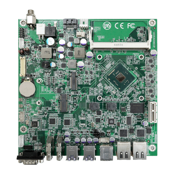
Getting Started 2.3. Jumpers & Connectors The board comes with some connectors to join some devices and also some jumpers to alter the hardware configuration. The following in this chapter will explicate each of these components one-by-one. 2.3.1. Layout This section will provide an overview of this board. Board Top ③... - Page 21 Getting Started Board Bottom SIM1 - 11 -...
-
Page 22: Jumpers
Getting Started 2.3.2. Jumpers ❶ JINV1 Function: LCD Inverter Voltage Selection Setting: Jumper Type: 2.54mm pitch 2x3-pin headers Description 12V (Default) Board Top 5.3mm JINV1 - 12 -... - Page 23 Getting Started ❷ JLCD1 Function: Setting: LCD Panel Voltage Selection Jumper Type: 2.54mm pitch 2x3-pin headers Pin Description 3.3V (Default) Board Top 5.3mm JLCD1 - 13 -...
- Page 24 Getting Started ❸ JBAT1 Function: Setting: Clear CMOS Selection Jumper Type: 2.54mm pitch 1x3-pin headers Pin Description Keep CMOS (Default) Clear CMOS Board Top 5.3mm JBAT1 - 14 -...
- Page 25 Getting Started ❹ JPIC2 Function: Setting: AT/ATX Power Mode Selection Jumper Type: 2.54mm pitch 1x3-pin headers Pin Description ATX (Default) Board Top 5.3mm JPIC2 - 15 -...
-
Page 26: Connectors
Getting Started 2.3.3. Connectors ① FAN1 Function: CPU Fan Power Connector Pin Assignment: Connector Type: 2.54mm pitch 1x4-pin one- Pin Description wall connector 1 GND 2 +12V 3 RPM 4 Control Note: The fan must be a 12V fan. Board Top FAN1 5.3mm - 16 -... - Page 27 Getting Started ② SAPO1 Function: Pin Assignment: SATA Power Connector Connector Type: 2.54mm pitch 1x4-pin wafer connector Pin Desc. V12S Board Top SAPO1 5.3mm - 17 -...
- Page 28 Getting Started ③ SATA1 Function: Serial ATA Connector Pin Assignment: Connector Type: Serial ATA Connector The pin assignments conform to the industry standard. Board Top SATA1 5.3mm - 18 -...
- Page 29 Getting Started ④ 24VIN1 Function: 24V DC IN Connector Pin Assignment: Connector Type: 4-pin power connector Pin Desc. Pin Desc. +24V +24V Chassis Chassis Board Top 24VIN1 5.3mm - 19 -...
- Page 30 Getting Started ⑤ DCIN1 Function: DC In Power Jack Pin Assignment: Connector Type: DC Φ7.4 Male connector Inner Shell :24V DC Outer Shell: Chassis GND Board Top DCIN1 5.3mm - 20 -...
- Page 31 Getting Started ⑥ Function: Front Panel LED & Audio Header Pin Assignment: Connector 2.54mm pitch 2x5-pin headers Pin Desc. Pin Desc. Type: RESET+ RESET- PLED+ PLED- HLED+ HLED- SPEAK+ SPEAK- PSON+ 10 PSON- Board Top 5.3mm - 21 -...
- Page 32 Getting Started ⑦ INV1 Function: Pin Assignment: Inverter Power Output Connector 2.00mm pitch 1x5-pin box Pin Desc. wafer connector Type: On/Off Brightness control Board Top 5.3mm INV1 - 22 -...
- Page 33 Getting Started ⑧ LVDS1 Function: LVDS Connector (30-Pin) Connector Type: DF-13-30DP-1.25V connector Pin Assignment: Pin Desc. Pin Desc. VDD2 VDD1 TX2_CLK+ TX1_CLK+ TX2_CLK- TX1_CLK- GND5 GND1 TX2_D0+ TX1_D0+ TX2_D0- TX1_D0- GND6 GND2 TX2_D1+ TX1_D1+ TX2_D1- TX1_D1- GND7 GND3 TX2_D2+ TX1_D2+ TX2_D2- TX1_D2- GND8...
- Page 34 Getting Started ⑨⑩ SPKR1/2 Function: Speaker Connector Pin Assignment: Connector Type: 1.25mm pitch 1x2 pin Description wafer connector INSPL+ INSPL- Board Top 5.3mm SPKR1 SPKR2 - 24 -...
- Page 35 Getting Started ⑪ AUDIO1 Function: Audio Header Pin Assignment: Connector Type: 2.0mm pitch 2x5 pin wafer Pin Desc. Pin Desc. connector LINE_R LINE_L GND1 GND3 MIC_L MIC_R GND2 GND4 10 LOUT_L LOUT_R Board Top 5.3mm AUDIO1 - 25 -...
- Page 36 Getting Started ⑫ KBMS1 Function: Keyboard & Mouse Pin Assignment: Connector Pin Desc. Connector Type: 2.0mm pitch 1x6-pin header KB_DATA MS_DATA KB_CLK PS2_VCC MS_CLK Board Top 5.3mm KBMS1 - 26 -...
- Page 37 Getting Started ⑬ COM1 Function: RS-232/422/485 Pin Assignment: Serial Connector Connector Type: DB-9 male connector RS232 RS422 RS485 Pin Desc. Desc. Desc. DCD# TX- Board Top 5.3mm COM1 - 27 -...
- Page 38 Getting Started ⑭⑮ HDMI1&2 Function: HDMI Connector Pin Assignment: Connector Type: 19-pin HDMI connector The pin assignments conform to the industry standard. Board Top 5.3mm HDMI2 HDMI1 - 28 -...
- Page 39 Getting Started ⑯⑰ USB1&2 Function: USB 3.0/2.0 Stack Pin Assignment: Connectors Connector Type: Double-stacked USB 3.0/2.0 The pin assignments type-A connectors conform to the industry standard. 1 2 3 4 1 2 3 4 Board Top 5.3mm USB2 USB1 - 29 -...
- Page 40 Getting Started ⑱ USB3 Function: USB 2.0 Stack Connectors Connector Double-stacked USB 2.0 Pin Assignment: Type: type-A connectors The pin assignments conform to the industry standard. Board Top 5.3mm USB3 - 30 -...
- Page 41 Getting Started ⑲ USB4 Function: USB 2.0 Connector Pin Assignment: Connector Type: 2.0mm pitch 2x5 pin wafer Pin Desc. Pin Desc. connector USBDN4N 3 USBDN3N USBDN4N 5 USBDN3P 10 GND Board Top 5.3mm USB4 - 31 -...
- Page 42 Getting Started LAN1&2 20 21 Function: Ethernet Connectors Pin Assignment: Connector Type: 10/100/1000Mbps fast The pin assignments Ethernet RJ-45 connector conform to the industry standard. Board Top 5.3mm LAN2 LAN1 - 32 -...
- Page 43 Getting Started PCIE1 Function: PCIe x1 Connector Connector Type: PCIe x1 Gen 2.0 slot Pin Assignment: The pin assignments conform to the industry standard. Board Top 5.3mm PCIE1 - 33 -...
- Page 44 Getting Started WIFI1 Function: NGFF M.2 E-Key Socket Connector Type: NGFF M.2 E-Key socket for WIFI, supporting 22x30 module Pin Assignment: The pin assignments conform to the industry standard. Board Top 5.3mm WIFI1 - 34 -...
- Page 45 Getting Started SSD1 Function: NGFF M.2 B-Key Socket Connector Type: NGFF M.2 B-Key socket for SSD, supporting 22x42 and 30x42 modules Pin Assignment: The pin assignments conform to the industry standard. Board Top 5.3mm SSD1 - 35 -...
- Page 46 Getting Started SIM1 Function: Micro SIM card socket (OEM request) Connector Type: REGO 80440GIH-061T-120L socket Pin Assignment: Pin Description Pin Description C1 VCC C2 RST C3 CLK C5 GND C6 VPP C7 I/O Board Bottom SIM1 - 36 -...
-
Page 47: Driver Installation Notes
Getting Started 2.4. Driver Installation Notes The board supports Windows 8.1. Find the necessary drivers on the CD that comes with your purchase. For different OS, the driver/utility installation may vary slightly, but generally they are similar. Find the drivers on CD by the following paths: Windows 8.1 Driver... - Page 48 This page is intentionally left blank. - 38 -...
-
Page 49: Chapter 3 - Bios
Chapter 3 BIOS Chapter 3 - BIOS - 39 -... - Page 50 BIOS The BIOS Setup utility is featured by AMI BIOS to configure the system settings stored in the system’s BIOS ROM. AMI BIOS is activated once the computer powers on. After entering the utility, use the left/right arrow keys to navigate between the top menus and use the down arrow key to access one.
-
Page 51: Main
Advanced Chipset Security Boot Save & Exit Main Set the Date. Use Tab to Switch BIOS Information between Date elements. BIOS Name ITX-i2203 BIOS Version Build Data and Time 03/01/2016 15:24:59 Access Level Administator System Date [Fri 03/04/2016] System Time [14:04:38] →←: Select Screen... -
Page 52: Advanced
BIOS 3.2. Advanced The Advanced menu controls the system’s CPU, IDE, Super IO, SATA and USB. It also helps users monitor hardware health. Aptio Setup Utility - Copyright (C) 2016 American Megatrends, Inc. Main Advanced Chipset Security Boot Save & Exit ACPI Settings System ACPI Parameters CPU Configuration... -
Page 53: Acpi Settings
BIOS 3.2.1. ACPI Settings Access this submenu to configure the highest ACPI sleep state when the system enters suspend. Aptio Setup Utility - Copyright (C) 2016 American Megatrends, Inc. Main Chipset Security Boot Save & Exit Advanced ACPI Settings Enables (default) or Disables System ability to Hibernate (OS/S4 Sleep State). -
Page 54: Cpu Configuration
BIOS 3.2.2. CPU Configuration Access this submenu to setup the CPU Configuration. Aptio Setup Utility - Copyright (C) 2016 American Megatrends, Inc. Advanced CPU Configuration Socket sepcific CPU Information Socket 0 CPU Information CPU Speed 1600 MHz 64-bit Supported Limit CPUID Maximum [Disabled] Bi-directional PROCHOT [Enabled]... -
Page 55: Ppm Configuration
BIOS Sets the Energy mode of the processor. Options available are: Disabled Energy Efficient (default) Custom Power Technology EIST :Enables (default) or Disable Intel Speed Step. • • Turbo Mode :Enables (default) or Disable Turbo Mode. • P-STATE Coordination : Change P-STATE coordination type. -
Page 56: Usb Configuration
BIOS 3.2.4. USB Configuration USB Configuration displays the status of USB connection and configures USB parameters. Aptio Setup Utility - Copyright (C) 2016 American Megatrends, Inc. Advanced USB Configuration Enables Legacy USB support. AUTO option disables legacy USB Module Version support if no USB devices are connected. -
Page 57: Sata Configuration
BIOS Configures the maximum time allowed for device to report itself to the Host Controller, . ► Options: Auto (default): Root port devices will be given 100 ms; a Device power-up delay hub port device will be given the time as specified in the hub descriptor, Manual: If set to Manual, a delay from 1 to 40 seconds can be selected. -
Page 58: Lpss & Scc Configuration
BIOS 3.2.6. LPSS & SCC Configuration Access this submenu to setup the LPSS & SCC Configuration Aptio Setup Utility - Copyright (C) 2016 American Megatrends, Inc. Advanced Enable or disable SATA Device. SCC Configuration SCC eMMC Support (D16:F0) [ACPI mode] LPSS Configuration LPSS with GPIO Device Support [Enabled]... -
Page 59: F81801 Super Io Configuration
BIOS 3.2.7. F81801 Super IO Configuration Access this submenu to setup the F81801 Super IO Configuration Aptio Setup Utility - Copyright (C) 2016 American Megatrends, Inc. Advanced Set Parameters of Serial Port F81801 Super IO Configuration 1 (COM1) Super IO Chip F81801 Serial Port 1 Configuration Power Failure... -
Page 60: Hardware Monitor
BIOS 3.2.8. Hardware Monitor Access this submenu to monitor of the overall inboard hardware health events, such as System temperature, CPU voltage, CPU & System fan speed... etc. Aptio Setup Utility - Copyright (C) 2016 American Megatrends, Inc. Advanced PC Health Status CPU Temperature System Temperature Fan1 Speed... -
Page 61: S5 Rtc Wake Settings
BIOS 3.2.9. S5 RTC Wake Settings Access this submenu to setup S5 RTC Wake Setting Aptio Setup Utility - Copyright (C) 2016 American Megatrends, Inc. Advanced Enables or disables [Disabled] Wake system from S5 system wake on alarm event. Select FixedTime, system will wake on the hr::min::sec specified. -
Page 62: Csm Configuration
BIOS 3.2.10. CSM Configuration Access this submenu to setup CSM Configuration Aptio Setup Utility - Copyright (C) 2016 American Megatrends, Inc. Advanced Compatibility Support Module Configuration UPON REQUEST - GA20 can be disabled using services. ALWAYS -do [Enabled] CSM Support not allow disabling GA20;... -
Page 63: Sdio Configuration
BIOS 3.2.11. SDIO Configuration Access this submenu to setup CSM Configuration Aptio Setup Utility - Copyright (C) 2016 American Megatrends, Inc. Advanced Auto Option: Access SD SDIO Configuration device in DMA mode if controller support it, [Auto] SDIO Access Mode otherwise in PIO mode. -
Page 64: Chipset
BIOS 3.3. Chipset Access this Chipset menu to configure the system’s chipset. Aptio Setup Utility - Copyright (C) 2016 American Megatrends, Inc. Main Advanced Security Boot Save & Exit Chipset North Bridge North Bridge Parameters South Bridge →←: Select Screen : Select Item Enter: Select +/-: Change Opt. -
Page 65: North Bridge
BIOS 3.3.1. North Bridge Access this submenu to configure North Bridge. Aptio Setup Utility - Copyright (C) 2016 American Megatrends, Inc. Chipset Intel IGD Configuration Config Intel IGD Settings. LCD Control Memory Information Total Memory 4096 MB (LPDDR3) →←: Select Screen : Select Item Enter: Select +/-: Change Opt. - Page 66 BIOS 3.3.1.1 Intel IGD Configuration Access this submenu to configure Intel IGD Configuration. Setting Description Enable and Disable GOP Driver GOP Driver ► Enabled is the default. Integrated Graphics Enable and Disable IGD. ► Device Enabled is the default. Select the IGD Turbo. If Auto selected, IGD Turbo will only be enabled IGD Turbo when SOC steeping is B0 or above.
- Page 67 BIOS 3.3.1.2 LCD Control Access this submenu to configure LCD Control. Setting Description Select LCD panel used by Internal Graphics Device by selecting the appropriate setup item. LCD Panel Type ► Options: 1024x768(default), 800x600, 1280x1024, 1366x768 LVDS and 1440x900 LVDS. Select LCD panel scaling option used by the Internal Graphics Panel Scaling Device.
-
Page 68: South Bridge
BIOS 3.3.2. South Bridge Access this submenu to configure South Bridge. Aptio Setup Utility - Copyright (C) 2016 American Megatrends, Inc. Chipset Azalia Configuration USB Configuration PCI Express Configuration →←: Select Screen : Select Item Enter: Select +/-: Change Opt. F1: General Help F2: Previous Values F9: Optimized Defaults... - Page 69 BIOS 3.3.2.1 Azalia Configuration Access this submenu to configure Azalia Configuration. Setting Description Enable and Disable Audio Controller Audio Controller ► Enabled is the default. 3.3.2.2 USB Configuration Access this submenu to configure USB Configuration. Setting Description Enable and Disable XHCI Mode XHCI Mode ►...
-
Page 70: Security
BIOS 3.4. Security The Security menu sets up the administrator password. Once an administrator password is set up, this BIOS Setup utility is limited to access and will ask for the password each time any access is attempted. Aptio Setup Utility - Copyright (C) 2016 American Megatrends, Inc. Main Advanced Chipset Boot... -
Page 71: Boot
BIOS 3.5. Boot Access this menu to change system boot settings. Aptio Setup Utility - Copyright (C) 2016 American Megatrends, Inc. Main Advanced Chipset Security Save & Exit Boot Number of seconds to wait for Boot Configuration setup activation key. Setup Prompt Timeout 65535 (0xFFFF) means indefinite Bootup Numlock State... -
Page 72: Save & Exit
BIOS 3.6. Save & Exit The Exit menu features a handful of commands to launch actions from the BIOS Setup utility regarding saving changes, quitting the utility and recovering defaults. Aptio Setup Utility - Copyright (C) 2016 American Megatrends, Inc. Main Advanced Chipset Security... -
Page 73: Appendices
Appendices Appendices - 63 -... -
Page 74: Appendix A. Anti-Crash Technology For Bios Recovering
Appendices Appendix A. Anti-Crash Technology for BIOS Recovering The motherboard supports Anti-Crash Technology (ACT) for automatical system BIOS recovering. This section describes the recovery process. A.1 Auto Recovery The motherboard comes with two BIOS ROMs mounted onto the board as shown below. -
Page 75: Bios Update Using Act Utility
Appendices The LED blinks fast to indicate erasing data from the master ROM. • The LED blinks slowly to indicate the MCU is writing system backup • BIOS from the slave ROM to the master one. The LED turns off to indicate the process is finished and the •... - Page 76 Appendices After running the program on command prompt, the utility performs these tasks: 1. Provides a specific protection to the BIOS. This ensures the BIOS will not become corrupted if power failure occurs while the BIOS update is in progress. 2.
-
Page 77: How To Get Act Utility
Advanced Chipset Security Boot Save & Exit Main Set the Date. Use Tab to Switch BIOS Information between Date elements. BIOS Name ITX-i2203 BIOS Version Build Data and Time 03/01/2016 15:24:59 Access Level Administator System Date [Fri 03/04/2016] System Time [14:04:38] →←: Select Screen... -
Page 78: Appendix B. I/O Port Address Map
Appendices Appendix B. I/O Port Address Map Each peripheral device in the system is assigned a set of I/O port addresses which also becomes the identity of the device. The following table lists the I/O port addresses used. Address Device Description 0x0000F080-0x0000F087 Microsoft Basic Display Adapter 0x000003B0-0x000003BB... - Page 79 Appendices Address Device Description 0x00000034-0x00000035 Programmable interrupt controller 0x00000038-0x00000039 Programmable interrupt controller 0x0000003C-0x0000003D Programmable interrupt controller 0x000000A0-0x000000A1 Programmable interrupt controller 0x000000A4-0x000000A5 Programmable interrupt controller 0x000000A8-0x000000A9 Programmable interrupt controller 0x000000AC-0x000000AD Programmable interrupt controller 0x000000B0-0x000000B1 Programmable interrupt controller 0x000000B4-0x000000B5 Programmable interrupt controller 0x000000B8-0x000000B9 Programmable interrupt controller 0x000000BC-0x000000BD...
-
Page 80: Appendix C. Interrupt Request Lines (Irq)
Appendices Appendix C. Interrupt Request Lines (IRQ) Peripheral devices use interrupt request lines to notify CPU for the service required. The following table shows the IRQ used by the devices on board. Level Function IRQ0 System timer IRQ4 SM Bus Controller IRQ8 High Precision Event Timer IRQ16... -
Page 81: Appendix D. Bios Memory Map
Introduction Appendix D. BIOS Memory Map Address Device Description 0xD0716000-0xD07167FF Standard SATA AHCI Controller 0xE0000000-0xEFFFFFFF Motherboard resources 0xFED01000-0xFED01FFF Motherboard resources 0xFED03000-0xFED03FFF Motherboard resources 0xFED04000-0xFED04FFF Motherboard resources 0xFED0C000-0xFED0FFFF Motherboard resources 0xFED08000-0xFED08FFF Motherboard resources 0xFED1C000-0xFED1CFFF Motherboard resources 0xFEE00000-0xFEEFFFFF Motherboard resources 0xFEF00000-0xFEFFFFFF Motherboard resources 0xD0000000-0xD03FFFFF Microsoft Basic Display Adapter 0xC0000000-0xCFFFFFFF... -
Page 82: Appendix E. Watchdog Timer (Wdt) Setting
Introduction Appendix E. Watchdog Timer (WDT) Setting WDT is widely used for industry application to monitor the activity of CPU. Ap- plication software depends on its requirement to trigger WDT with adequate timer setting. Before WDT time out, the functional normal system will reload the WDT. - Page 83 Introduction delay(DELAY_TIME); /* Watchdog Timer Control Register */ SMB_Byte_WRITE(SMB_PORT_AD,SMB_DEVICE_ADD,0x36,0x72); int WDT_Count(void) int iData; /* Watchdog Timer Range Register */ iData = SMB_Byte_READ(SMB_PORT_AD,SMB_DEVICE_ADD,0x37); return iData; void WDT_Clear(int iCount) /* Watchdog Timer Range Register */ SMB_Byte_WRITE(SMB_PORT_AD,SMB_DEVICE_ADD,0x37,iCount); void WDT_Stop(void) /* Watchdog Timer Control Register */ SMB_Byte_WRITE(SMB_PORT_AD,SMB_DEVICE_ADD,0x36,0x52); - 73 -...
Need help?
Do you have a question about the ITX-i2203 and is the answer not in the manual?
Questions and answers