
Subscribe to Our Youtube Channel
Related Manuals for Arbor Technology ITX-a55E3


Summary of Contents for Arbor Technology ITX-a55E3
- Page 1 ITX-a55E3 AMD Fusion G-T40N Mini-ITX Industrial Motherboard User’s Manual Version 1.2 2016.11...
- Page 2 Revision History Version Date Description 2013/05/17 Initial Release 2014/05/07 Revise P.21 LVDS1 Pin definition. • Remove “UPS Function Support” feature from 1.1 The Product • Remove G-T56N 1.65GHz processor from 1.3 Specifications 1.5 Ordering Infor- mation • Remove connector “J10” from 2.3 Jumpers and Connectors •...
-
Page 3: Table Of Contents
Contents Preface Copyright Notice ..............iii Declaration of Conformity ............iii CE ....................iii FCC Class B ................iii RoHS ..................iv SVHC / REACH ................v Warning ..................v Replacing the Lithium Battery ..........v Technical Support ..............vi Warranty ...................vi Chapter 1 - Introduction ..........1 1.1 The Product................2 1.2 About This Manual ............2 1.3 Specifications ..............3 1.4 Inside the Package ............4... - Page 4 Contents 3.4 Installing PCI Card............36 3.5 Installing PCIe Card............36 Chapter 4 - BIOS ............37 4.1 Main ..................38 4.2 Advanced .................40 4.2.1 PCI Subsystem Settings ..........41 4.2.2 ACPI Settings ..............43 4.2.3 IDE Configuration ............44 4.2.4 USB Configuration ............45 4.2.5 F81866 Super IO Configuration ........46 4.2.6 F81866 H/W Monitor ............48 4.3 Chipset ................49 4.3.1 North Bridge ..............50...
-
Page 5: Preface
Preface Copyright Notice All Rights Reserved. The information in this document is subject to change without prior notice in order to improve the reliability, design and function. It does not represent a commitment on the part of the manufacturer. Under no circumstances will the manufacturer be liable for any direct, indirect, special, incidental, or consequential damages arising from the use or inability to use the product or documentation, even if advised of the possibility of such damages. -
Page 6: Rohs
-- Consult the dealer or an experienced radio/TV technician for help. RoHS ARBOR Technology Corp. certifies that all components in its products are in compliance and conform to the European Union’s Restriction of Use of Haz- ardous Substances in Electrical and Electronic Equipment (RoHS) Directive 2002/95/EC. -
Page 7: Svhc / Reach
Preface SVHC / REACH To minimize the environmental impact and take more responsibility to the earth we live, Arbor hereby confirms all products comply with the restriction of SVHC (Substances of Very High Concern) in (EC) 1907/2006 (REACH --Registration, Evaluation, Authorization, and Restriction of Chemicals) regulated by the European Union. -
Page 8: Technical Support
Preface Technical Support If you have any technical difficulties, please consult the user’s manual first ftp://ftp.arbor.com.tw/pub/manual Please do not hesitate to call or e-mail our customer service when you still can- not find out the answer. http://www.arbor-technology.com E-mail:info@arbor.com.tw Warranty This product is warranted to be in good working order for a period of two years from the date of purchase. -
Page 9: Chapter 1 Introduction
Introduction Chapter 1 Introduction - 1 -... -
Page 10: The Product
Introduction 1.1 The Product ITX-a55E3 is built on standard form factor to allow system upgrade without much of the concern on compatibility. The Industrial Motherboard coming with mounting holes and a piece of I/O bracket is designed to reduce cabling and total cost. -
Page 11: Specifications
Introduction 1.3 Specifications System Soldered onboard AMD G-Series Processor Processor G-T40N 1.0GHz ® Chipset FCH A55E Memory Soldered Onboard 2GB DDR3 BIOS AMI BIOS Watchdog Timer 1~255 levels reset I/O Chip Fintek F81866D-I 4 x RS-232 ports Serial Port 2 x RS-232/485 selectable 6-pin wafer connector for PS/2 keyboard/ mouse via Keyboard &... -
Page 12: Inside The Package
1.4 Inside the Package Before you begin installing your Industrial motherboard, make sure the following materials have been shipped: 1 x ITX-a55E3 Mini-ITX industrial motherboard 1 x Driver CD 1 x Quick Installation Guide 1 x DVI cable (DVI-29M to DVI-29F+DB-15F) If any of the above items is damaged or missing, contact your vendor im- mediately. -
Page 13: Ordering Information
Introduction 1.5 Ordering Information ITX-a55E3-T40N AMD G-T40N Embedded Mini-ITX motherboard 1.5.1 Optional Accessories SCDB-5190 PCIe x1 Riser Card Cable kit • 2 x USB cables • 2 x Two-port-serial cables • 2 x Serial-port RJ-45 cables CBK-11-55E3-00 • 1 x KB/MS Y-cable •... -
Page 14: The Installation Paths Of Cd Driver
Find the drivers on CD by the following paths: Windows 7 Driver Path CHIPSET \ITX-a55E3\Win7\Chipset \ITX-a55E3\Win7\Ethernet AUDIO \ITX-a55E3\Win7\Audio Touch Panel \ITX-a55E3\Win7\Touch Panel Net Framework 4.0 \ITX-a55E3\Win7\Net framework 4.0 Windows XP Driver Path CHIPSET \ITX-a55E3\WinXP\Chipset \ITX-a55E3\WinXP\Ethernet AUDIO \ITX-a55E3\WinXP\Audio Touch Panel \ITX-a55E3\WinXP\Touch Panel\WinXP Net Framework 4.0 \ITX-a55E3\WinXP\Net framework 4.0... -
Page 15: Chapter 2 - Board Overview
Board Overview Chapter 2 Board Overview - 7 -... -
Page 16: Board Dimensions
Board Overview 2.1 Board Dimensions The following illustration shows the dimension of ITX-a55E3, with the measure- ments in width, depth, and height called out. 170.00 6.33 157.48 20.0 44.50 66.41 91.50 108.90 126.41 145.80 163.81 Unit: mm - 8 -... -
Page 17: Block Diagram
Board Overview 2.2 Block Diagram Soldered onboard Chrontel Single Channel DDR3 Dual Channels 2GB DDR3 CH7511 LVDS connector 800/ 1066MHz 24-bit LVDS SDRAM eDP to LVDS transmitter Soldered Realtek ® Analog R.G.B. 2 x PCIex1 onboard LAN1 ~ LAN2 RTL8111E DVI-I connector AMD APU GbE controller... -
Page 18: Jumpers And Connectors
Jumpers/ Connectors Quick Reference Board Overview 2.3 Jumpers and Connectors 2.3.1 Jumpers/ Connectors Quick Reference Jumpers Label Description JPWR1 AT/ATX Power Selection Back Light Brightness Setting JBTM1 Reserved JCOM5 5V/12V (Pin 10) Selection JCOM6 5V/12V (Pin 10) Selection JBAT1 Clear CMOS Selection JVLCD1 LCD Panel Voltage Selection Connectors... -
Page 19: Location
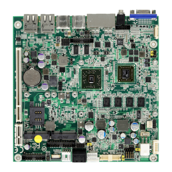
Board Overview 2.3.2 Location Jumpers Location JPWR1 JVLCD1 JCOM6 JBAT1 JBTM1 JCOM5 - 11 -... - Page 20 Board Overview Connectors Location 12VIN1 LVDS1 KBMS1 SATA0 TPC3 COM4 5W_T1 SAPO1 INV1 DIO1 PCIE1 JFRT1 FAN1 SIM1 PCI1 USB3 USB4 AUDIO1 USB1 COM3 LAN2 LAN1 COM1 DVI1 USB2 - 12 -...
-
Page 21: Jumpers
Board Overview 2.3.3 Jumpers The jumper is “short” (closed) when the jumper cap is placed on pins. If not, that means the jumper is “open.” The following in this section will explicate each of the components one-by-one. Pin short Pin 2-3 short Pin 1-2 short Pin open (closed) - Page 22 Board Overview J13 (2) JBAT1 (5) Function: Back Light Brightness Setting Function: Clear CMOS Selection Jumper type: 2.54mm pitch 1x3-pin Jumper type: 2.54mm pitch 1x3-pin header header Setting: Setting: Mode Mode Keep CMOS data For LED Panel (default) (default) Clear CMOS data For CCFL Panel JPWR1 JVLCD1...
- Page 23 Board Overview JBTM1 (3) Function: Reserved Jumper type: 2.00mm pitch 2x3-pin header Pin 2/4/6 are used only for updating firmware. General user doesn’t need to set them. JPWR1 JVLCD1 JCOM6 JBAT1 JBTM1 JCOM5 - 15 -...
- Page 24 Board Overview JVLCD1 (7) Function: LCD Panel Voltage Selection The voltage of LCD panel is selected by JVLCD. Jumper type: 2.54mm pitch 1x3-pin header Setting: Mode VCC_LCD=5V VCC_LCD=3.3V (default) JPWR1 JVLCD1 JCOM6 JBAT1 JBTM1 JCOM5 - 16 -...
- Page 25 Board Overview JCOM5/6 (4, 6) Function: 5V/12V (Pin 10) Selection JCOM5 controls COM Port 1/2; JCOM6 controls COM Port 5/6. Jumper type: 2.00mm pitch 2x3-pin header Setting: Mode 2 4 6 2 4 6 2 4 6 2 4 6 COM Port 1 or 5 supports outputting 5V power (default) 1 3 5...
-
Page 26: Connectors
Board Overview 2.3.4 Connectors TPC3 (9) Function: Touch Panel Membrane Connector Connector type: 0.5mm pitch 1x6-pin header Description Backlight Decrement Backlight Increment Power Button Reserved Reserved LVDS1 12VIN1 5W_T1 KBMS1 SATA0 TPC3 COM4 SAPO1 INV1 DIO1 PCIE1 JFRT1 FAN1 SIM1 PCI1 USB3 USB4... - Page 27 Board Overview SAPO1 (10) SATA0 (11) Function: Serial ATA Power Connector Function: Double Stacked Serial ATA Connector type: 2.54mm pitch 1x4-pin Connector High speed transfer rates wafer one wall 90D connector (600MB/s) Description +12V LVDS1 SATA0 TPC3 COM4 12VIN1 5W_T1 KBMS1 SAPO1 INV1...
- Page 28 Board Overview DIO11 (12) INV1 (13) Function: DIO Connector Function: LVDS Invertor Connector DIO1 is a 8-bit DIO connector w/ onboard Connector type: 2.00mm pitch 1x5 10-pin headers connector, supports pro- box wafer connector grammable Input and Output. Pin Description Connector type: 2.00 mm pitch 2x5-pin 1 +12V headers...
- Page 29 Board Overview 5W_T1 (16) KBMS1 (14) Function: 5 Wire Touch Panel Connector Function: PS/2 Keyboard and Mouse Con- Connector type: 2.54mm pitch 1x5-pin nector header Connector type: 2.0mm pitch 1x6-pin box wafer connector Description Description KB_DATA PROBE MS_DATA KB_CLK PS2_VCC MS_CLK LVDS1 12VIN1...
- Page 30 Board Overview LVDS1 (15) Function: LVDS Connector Connector type: DF-13-30DP-1.25V connector Pin Desc. Pin Desc. 2 VDD 1 VDD 4 TX2CLK+ 3 TX1CLK+ 6 TX2CLK- 5 TX1CLK- 8 GND 7 GND 10 TX2D0+ 9 TX1D0+ 12 TX2D0- 11 TX1D0- 14 GND 13 GND 16 TX2D1+ 15 TX1D1+...
- Page 31 Board Overview 12VIN1 (17) JFRT1 (18) Function: 9~36V Power Input Connector Function: Front Panel Connector 12INV1 supplies the CPU operation ATX Connector type: 2.00mm pitch 2x5-pin header +9~36V (Vcore). Pin Desc. Pin Desc. Pin Desc. Pin Desc. RESET+ RESET- POWER LED+ 4 POWER LED- 9~36V 9~36V...
- Page 32 Board Overview FAN1 (19) AUDIO1 (20) Function: CPU Fan Connector Function: Audio output Connector type: 2.54mm pitch 1x3 box External connector: Black 3.5mmφ 3-pin line-out wafer connector jack Pin Description Connector type: 2.00mm pitch 2x5-pin box header Pin Desc. Pin Desc. +12V 1 Line_In_Left 2 Line_In_Right...
- Page 33 Board Overview COM1 (22) DVI1 (21) Function: RS-232/RS-485 Connectors Function: DVI-I Connector Connector type: RJ-45 jack COM Port 4 COM Port 3 C1 C2 C3 C4 DSR#4 / D4- DSR#3 / D3- DCD#4 / D4+ DCDE#3 / D3+ DTR#4 DTR#3 RXD4 RXD3 COM Port 4 COM Port 3...
- Page 34 Board Overview LAN1/2 (27, 26) Function: Ethernet Connectors Support 10/100/1000 Mbps fast Ethernet. Connector type: RJ-45 USB1/2 (25, 23) 1 2 3 4 Function: Double Stacked USB type A Connectors 1 2 3 4 12VIN1 LVDS1 KBMS1 SATA0 TPC3 COM4 5W_T1 SAPO1 INV1...
- Page 35 Board Overview COM3/4 (24, 8) Function: RS-232 Connector Connector type: 2.00mm pitch 2x10-pin header Pin Description Pin Description DCD#1/5 RXD1/5 TXD1/5 DTR#1/5 DSR#1/5 RTS#1/5 CTS#1/5 RI#1/5 10 +5V/ +12V DCD#2/6 12 RXD2/6 TXD2/6 14 DTR#2/6 19 20 16 DSR#2/6 RTS#2/6 18 CTS#2/6 RI#2/6 20 +5V/ +12V...
- Page 36 Board Overview USB3/4 (29, 28) Function: USB Port Connectors Connector type: 2.00mm pitch 2x5-pin headers Pin Desc. PinDesc. 1 +5V 2 +5V 3 USBD- 4 USBD- 5 USBD+ 6 USBD+ 7 GND 8 GND 9 GND 10 N/C (Key) LVDS1 SATA0 TPC3 COM4...
- Page 37 Board Overview MC1 (30) MC2 (31) Function: Mini-Card Socket Function: mSATA Socket Connector type: Onboard 0.8mm pitch Connector type: Onboard 0.8mm-pitch 52-pin edge card connector. The pin 52-pin edge card connector intercon- nected with SIM card socket. assignments conform to the industry standard.
- Page 38 Board Overview SIM1(32) Function: SIM card socket Connector type: KINGFONT SIMMP-00601B200-G socket Pin Desc. Pin Desc. C1 VCC C2 RST C3 CLK C5 GND C6 VPP C7 I/O 12VIN1 LVDS1 KBMS1 SATA0 TPC3 COM4 5W_T1 SAPO1 INV1 DIO1 PCIE1 JFRT1 FAN1 SIM1 PCI1...
- Page 39 Board Overview PCIE1 (33) Function: PCIe x1 Slot Connector type: PCIe x1 Gen 2.0 slot The pin assignments conform to the industry standard. PCI1 (34) Function: PCI Slot Connector type: 32-bit PCI slot The pin assignments conform to the industry standard. LVDS1 12VIN1 5W_T1...
- Page 40 This page is intentionally left blank. - 32 -...
-
Page 41: Chapter 3 - Hardware Installation
Hardware Installation Chapter 3 Hardware Installation - 33 -... -
Page 42: Installing The Heatsink
Hardware Installation 3.1 Installing the Heatsink 1. Find the heatsink accomanied with the board. 2. Screw the heatsink to ITX-a55E3 as shown at red circles. PCIe x1 connector Mini-card socket mSATA socket - 34 -... -
Page 43: Installing Mini-Card
3. Press down the Mini-card and fix it in place using two screws. 3.3 Installing SIM Card 1. Position SIM card socket on ITX-a55E3. 2. Slightly press SIM socket lid and move it rightards. Lift socket lid. 3. Slip SIM card along grooves on lid's inside as below, close it and move leftwards. -
Page 44: Installing Pci Card
Hardware Installation 3.4 Installing PCI Card 1. Position PCI slot on ITX-a55E3. 2. Insert PCI card into its slot as illustration. 3.5 Installing PCIe Card 1. To Install PCIex1 card, need purchase another riser card included in optional items. (1.5.1... -
Page 45: Chapter 4 - Bios
BIOS Chapter 4 BIOS - 37 -... -
Page 46: Main
Choose the system default BIOS Vendor American Megatrends language Core Version 4.6.5.1 Compliancy UEFI 2.3; PI 1.2 Project Version iTX-a55E3 1.01 Build Date and Time 03/28/2013 10:16:03 Memory Information Total Memory 2032 MB (DDR3) Select Screen Select Item Enter Select... - Page 47 BIOS Set the system time. Use Tab to switch between Time elements. System Time The time format is: Hour: 00 to 23 ► Minute: 00 to 59 Second: 00 to 59 Key Commands BIOS Setup Utility is mainly a key-based navigation interface. Please refer to the following key command instructions for navigation process.
-
Page 48: Advanced
BIOS 4.2 Advanced The “Advanced” setting page provides you the options to configure the details of your hardware, such as PCI, ACPI, IDE, USB and Super IO. Aptio Setup Utility - Copyright (C) 2011 American Megatrends, Inc. Chipset Boot Security Save &... -
Page 49: Pci Subsystem Settings
BIOS 4.2.1 PCI Subsystem Settings Aptio Setup Utility - Copyright (C) 2011 American Megatrends, Inc. Advanced V 2.05.01 PCI Bus Driver Version In case of multiple Option ROMs (Legacy and EFI Compatible), PCI Option ROM Handling specifies what PCI Option ROM [Legacy ROM] PCI ROM Priority to launch. - Page 50 BIOS PCI Express Settings Aptio Setup Utility - Copyright (C) 2011 American Megatrends, Inc. Advanced PCI Express Device Register Settings Set the ASPM Level: Force L0s - Force all links to L0s State: AUTO PCI Express Link Register Settings - BIOS auto configure: DISABLE [Disabled] ASPM Support - Disables ASPM...
-
Page 51: Acpi Settings
BIOS 4.2.2 ACPI Settings Aptio Setup Utility - Copyright (C) 2011 American Megatrends, Inc. Advanced ACPI Settings Enables or Disables BIOS ACPI Auto Configuration. Enable ACPI Auto Configuration [Disabled] Enable Hibernation [Enabled] ACPI Sleep State [S3 (Suspend to RAM)] Select Screen Select Item Enter Select... -
Page 52: Ide Configuration
BIOS 4.2.3 IDE Configuration Aptio Setup Utility - Copyright (C) 2011 American Megatrends, Inc. Advanced IDE Configuration SATA Port0 Not Present SATA Port1 Not Present SATA Port2 Not Present Select Screen Select Item Enter Select Change Opt. General Help Previous Values Optimized Defaults Save &... -
Page 53: Usb Configuration
BIOS 4.2.4 USB Configuration Aptio Setup Utility - Copyright (C) 2011 American Megatrends, Inc. Advanced Enable Legacy USB support. USB Configuration AUTO option disables legacy USB Devices: support if no USB devices are 1 Keyboard, 1 Mouse, 1 Point connected. DISABLE option will keep USB devices available only Legacy USB Support [Enabled]... -
Page 54: F81866 Super Io Configuration
BIOS 4.2.5 F81866 Super IO Configuration Aptio Setup Utility - Copyright (C) 2011 American Megatrends, Inc. Advanced Set Parameters of Serial Port 0 F81866 Super IO Configuration (COMA) F81866 Super IO Chip F81866 Serial Port 0 Configuration Serial Port 1 Configuration Serial Port 2 Configuration Serial Port 3 Configuration Serial Port 4 Configuration... - Page 55 BIOS Serial Port 0~5 Configuration Aptio Setup Utility - Copyright (C) 2011 American Megatrends, Inc. Advanced Enable or Disable Serial Port Serial Port 0~5 Configuration (COM) Serial Port [Enabled] Device Settings IO=3F8h; IRQ=4; Change Settings [IO=3F8h; IRQ=4;] Select Screen Select Item Enter Select Change Opt.
-
Page 56: F81866 H/W Monitor
BIOS 4.2.6 F81866 H/W Monitor Aptio Setup Utility - Copyright (C) 2011 American Megatrends, Inc. Advanced Pc Health Status CPU temperature : +39 C System temperature : +33 C Fan1 Speed : 6493 RPM VCORE : +1.344 V 5VALW : +5.087 V : +5.129 V Select Screen : +11.968 V... -
Page 57: Chipset
BIOS 4.3 Chipset Aptio Setup Utility - Copyright (C) 2011 American Megatrends, Inc. Advanced Chipset Boot Security Save & Exit Main North Bridge Parameters North Bridge North Bridge LVDS Config Select South Bridge Select Screen Select Item Enter Select Change Opt. General Help Previous Values Optimized Defaults... -
Page 58: North Bridge
BIOS 4.3.1 North Bridge Aptio Setup Utility - Copyright (C) 2011 American Megatrends, Inc. Chipset North Bridge Configuration Select Primary Video Device that BIOS will use for output. Primary Video Device [IGD Video] Memory Information Memory Clock: 533 MHz Total Memory: 2032 MB (DDR3) Select Screen Select Item Enter... -
Page 59: North Bridge Lvds Config Select
BIOS 4.3.2 North Bridge LVDS Config Select Aptio Setup Utility - Copyright (C) 2011 American Megatrends, Inc. Chipset Specify INT15 options for LVDS NB PCIe Connect Type (Display DP0 Output Mode [LVDS] device) DP1 Output Mode [Single Link DVI-D] LVDS Resolution [LVDS Option 1024 X...] Select Screen Select Item... -
Page 60: South Bridge
BIOS 4.3.3 South Bridge Aptio Setup Utility - Copyright (C) 2011 American Megatrends, Inc. Chipset SB CIM Version : 1.1.1.3 Options for SATA Configuration SB SATA Configuration SB USB Configuration Select Screen Select Item Enter Select Change Opt. General Help Previous Values Optimized Defaults Save &... - Page 61 BIOS SB SATA Configuration Aptio Setup Utility - Copyright (C) 2011 American Megatrends, Inc. Chipset OnChip SATA Channel [Enabled] Enable or Disable Serial ATA OnChip SATA Type [Legacy IDE] SATA IDE Combined Mode [Enabled] Combined Mode Option [SATA as primary] Select Screen Select Item Enter...
- Page 62 BIOS SB USB Configuration Aptio Setup Utility - Copyright (C) 2011 American Megatrends, Inc. Chipset OHCI HC (Bus 0 Dev 18 Fn 0) [Enabled] Enable or Disable OHCI HC (Bus OHCI HC (Bus 0 Dev 19 Fn 0) [Enabled] 0 Dev 18 Fn 0) OHCI HC (Bus 0 Dev 22 Fn 0) [Enabled] OHCI HC (Bus 0 Dev 20 Fn 5)
-
Page 63: Boot
BIOS 4.4 Boot Aptio Setup Utility - Copyright (C) 2011 American Megatrends, Inc. Advanced Chipset Boot Security Save & Exit Main Number of seconds to wait for Boot Configuration Setup Prompt Timeout setup activation key. Boot NumLock State [On] 65535 (0xFFFF) means indefinite waiting. -
Page 64: Security
BIOS 4.5 Security The Security menu sets up the administrator password. Once an administrator password is set up, this BIOS SETUP utility is limited to access and will ask for the password each time any access is attempted. Aptio Setup Utility - Copyright (C) 2011 American Megatrends, Inc. Advanced Chipset Boot... -
Page 65: Save & Exit
BIOS 4.6 Save & Exit Aptio Setup Utility - Copyright (C) 2011 American Megatrends, Inc. Advanced Chipset Boot Security Save & Exit Main Exit system setup after saving Save Changes and Exit Restore Defaults the changes. Boot Override Select Screen Select Item Enter Select... - Page 66 This page is intentionally left blank. - 58 -...
-
Page 67: Appendix
Appendix Appendix - 59 -... -
Page 68: Appendix A: I/O Port Address Map
Appendix Appendix A: I/O Port Address Map Each peripheral device in the system is assigned a set of I/O port addresses which also becomes the identity of the device. The following table lists the I/O port addresses used. Address Device Description 0x00000000-0x0000000F Direct memory access controller 0x00000000-0x0000000F... - Page 69 Appendix 0x000003B0-0x000003BB PCI bus 0x000003C0-0x000003DF AMD Radeon HD 6250 Graphics 0x00000061-0x00000061 System speaker 0x000003E0-0x00000CF7 PCI bus 0x00000D00-0x0000FFFF PCI bus 0x00000070-0x00000071 System CMOS/real time clock 0x00000010-0x0000001F Motherboard resources 0x00000022-0x0000003F Motherboard resources 0x00000044-0x0000005F Motherboard resources 0x00000062-0x00000063 Motherboard resources 0x00000065-0x0000006F Motherboard resources 0x00000072-0x0000007F Motherboard resources 0x00000080-0x00000080 Motherboard resources...
- Page 70 Appendix 0x00000C6C-0x00000C6C Motherboard resources 0x00000C6F-0x00000C6F Motherboard resources 0x00000CD0-0x00000CD1 Motherboard resources 0x00000CD2-0x00000CD3 Motherboard resources 0x00000CD4-0x00000CD5 Motherboard resources 0x00000CD6-0x00000CD7 Motherboard resources 0x00000CD8-0x00000CDF Motherboard resources 0x00000800-0x0000089F Motherboard resources 0x00000B20-0x00000B3F Motherboard resources 0x00000900-0x0000090F Motherboard resources 0x00000910-0x0000091F Motherboard resources 0x0000FE00-0x0000FEFE Motherboard resources 0x00000170-0x00000177 ATA Channel 1 0x00000376-0x00000376 ATA Channel 1 0x000000F0-0x000000FF...
-
Page 71: Appendix B: Interrupt Request Lines (Irq)
Appendix Appendix B: Interrupt Request Lines (IRQ) Peripheral devices use interrupt request lines to notify CPU for the service required. The following table shows the IRQ used by the devices on board. Level Function IRQ 0 System timer IRQ 1 Standard PS / 2 Keyboard IRQ 3 Communications Port (COM2) - Page 72 Appendix 0xFEB00000-0xFEB3FFFF AMD Radeon HD 6250 Graphics 0xA0000-0xBFFFF AMD Radeon HD 6250 Graphics 0xA0000-0xBFFFF PCI bus 0xC0000-0xDFFFF PCI bus 0x7F000000-0xFFFFFFFF PCI bus 0xFEB40000-0xFEB43FFF High Definition Audio Controller Standard Enhanced PCI to USB Host Con- 0xFEB48000-0xFEB480FF troller 0xE0000000-0xEFFFFFFF System board 0xFEB4E000-0xFEB4EFFF Standard OpenHCD USB Host Controller 0x67000000-0x7EFFFFFF Motherboard resources...
-
Page 73: Appendix D: Watchdog Timer (Wdt) Setting
Appendix Appendix D: Watchdog Timer (WDT) Setting WDT is widely used for industry application to monitor the activity of CPU. Ap- plication software depends on its requirement to trigger WDT with adequate timer setting. Before WDT time out, the functional normal system will reload the WDT. -
Page 74: Appendix E: Digital I/O Setting
Appendix Appendix E: Digital I/O Setting Below are the source codes written in C, please take them for Digital I/O application examples. The default I/O address is 6Eh. /*----- Include Header Area -----*/ #include “math.h” #include “stdio.h” #include “dos.h” #define SIO_INDEX 0x2E /* or index = 0x4E */ #define SIO_DATA... - Page 75 Appendix Digital IO usage table (Super IO chipset Fintek F81866D-I) Description Chipset Pin # Chipset Pin description DIO1 GPIO80 DIO2 GPIO81 DIO3 GPIO82 DIO4 GPIO83 DIO5 GPIO84 DIO6 GPIO85 DIO7 GPIO86 DIO8 GPIO87 - 67 -...
Need help?
Do you have a question about the ITX-a55E3 and is the answer not in the manual?
Questions and answers