Table of Contents
Advertisement
Quick Links
Form Factor
Mini-ITX
Video
Dual Channel 18/24-bit
LVDS/ DVI-I
I/O
PCIe/ SATA/ USB/ COM/
DIO/ Mini-card
♦ Technical Support
If you have any technical difficulties, please consult the user's manual first at:
ftp://ftp.arbor.com.tw/pub/manual
Please do not hesitate to call or e-mail our customer service when you still can not
find out the answer.
http://www.arbor.com.tw
E-mail: info@arbor.com.tw
Copyright
2012 All Rights Reserved.
®
ITX-i67M0
Mini-ITX Industrial Motherboard
CPU
Soldered onboard Intel®
Core™ i7/i5/i3,Celeron®
in rPGA988 (Socket G2)
LAN
1 x Intel® 82579LM PCIe
GbE PHY w/ iAMT,
1 x Intel® 82583V GbE
Controllers
FOR HOME OR OFFICE USE
- 1 -
Quick Installation Guide
Chipset
Intel® QM67
Audio
Realtek ALC886 codec
(Line-in/ Line-out/ Mic-in)
Tested To Comply
With FCC Standards
Version 1.1
4041670000110P
Advertisement
Table of Contents

Subscribe to Our Youtube Channel
Related Manuals for Arbor Technology ITX-i67M0


Summary of Contents for Arbor Technology ITX-i67M0
-
Page 1: Technical Support
ITX-i67M0 Mini-ITX Industrial Motherboard Quick Installation Guide Version 1.1 Form Factor Chipset Mini-ITX Soldered onboard Intel® Intel® QM67 Core™ i7/i5/i3,Celeron® in rPGA988 (Socket G2) Video Audio Dual Channel 18/24-bit 1 x Intel® 82579LM PCIe Realtek ALC886 codec LVDS/ DVI-I GbE PHY w/ iAMT, (Line-in/ Line-out/ Mic-in) 1 x Intel®... -
Page 2: Packing List
Packing List Before you begin installing your single board, please make sure that the following materials have been shipped: 1 x ITX-i67M0 Mini-ITX industrial motherboard 1 x Driver CD 1 x Quick Installation Guide 1 x CPU Cooler 1 x I/O Bracket If any of the above items is damaged or missing, contact your vendor immediately. - Page 3 The Installation Paths of CD Driver (V4.1A) Windows XP Driver Path CHIPSET \CHIPSET\INTEL\INF 9.2.0.1021 NET Framework \NET Framework\NET Framework 3.5 \ME\AMT_INTEL_V7.0.0.1109 GRAPHICS \GRAPHICS\INTEL\Winxp_14464 \ETHERNET\WIN_allos_Ver16.3 AUDIO \AUDIO\Realtek_HD\XP_2000 WDM_R261 32_64 bit Windows 7 Driver Path CHIPSET \CHIPSET\INTEL\INF 9.2.0.1021 \ME\AMT_INTEL_V7.0.0.1109 \GRAPHICS\INTEL_Win7_32\2291 GRAPHICS \GRAPHICS\INTEL_Win7_64\2291 \ETHERNET\WIN_allos_Ver16.3 AUDIO \AUDIO\Realtek_HD\Vista_Win7_R261-32_64 bit...
-
Page 4: Specifications
Specifications Form Factor Mini-ITX Industrial Motherboard Soldered onboard Intel® Core™ i7/i5/i3, Celeron® processor in rPGA988 (Socket G2) Chipset Intel® QM67 2 x 204-pin DDR3 SO-DIMM sockets supporting 1066/1333 MHz System Memory SDRAM up to 8GB Integrated Intel® HD Graphics 3000 Graphics Controller DVI-I/ Dual Channels 18/24-bit LVDS I/O Chip... -
Page 5: Board Dimensions
Board Dimensions 162.28 169.98 KB/MS USB*4 Line in/out/Mic COM/DVI-I LAN/USB LAN/USB 10.28 42.4 75.05 96.91 118.38 137.38 Unit: mm - 5 -... - Page 6 Jumpers/ Connectors Quick Reference Jumpers Label Description JPWR1 AT/ATX Power Mode Selection JBAT1 CMOS Keep Up Selection JRS1 COM2 RS-232 / 422 / 485 Selection CON1 COM2/3 Power Source Select on Pin 9 JME1 ME Function Select Connectors Label Description JSPI1 SPI Flash for External SPI Programming Tools USB1...
-
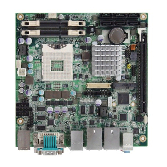
Page 7: Jumpers & Connectors Location
Jumpers & Connectors Location SATA2 SATA4 SATA6 JFRT1 FAN2 PWROUT1 SATA1 SATA3 SATA5 JME1 DIMM2 JPWR1 DIMM1 JSPI1 rPGA-988 JBAT1 FAN1 12VIN1 USB2 COM6 COM5 LVDS1 DIO1 CON1 COM4 COM2 COM3 INV1 JRS1 LPC1 KBUSB1 USB1 LAN1 LAN2 AUDIO1 DVI1 COM1 - 7 -... -
Page 8: Jumper Settings
Jumpers JME1: ME Function Select (32) Connector type: 2.00mm pitch 1x3-pin header Jumper Settings Power Mode Selection The jumper is “short” (closed) when the jumper cap is placed on pins. If not, that means the jumper is “open.” ME Enable/ME Flash disable (Default) ME Disable/ME Flash Pin 1-2 short... - Page 9 LVDS1: LVDS Connector (6) LAN1, 2: Ethernet Connectors (include Connector type: DF-13-40DP-1.25V connector USB0/1/2/3 Connector) (9, 8) Pin Desc. Pin Desc. Connector type: RJ-45 + double stacked USB type A connector. VCC3 VCC3 LAN (RJ-45) Desc. VCC5 VCC5 MDI0+ MDI0- LVDSA_DATA1- 9 LVDSA_DATA0- MDI1+...
- Page 10 DVI1: DVI-I Connector (12) COM2: Serial Port Connector (16) Connector type: 2.00mm pitch 2x7-pin box header Pin Desc. Desc. C1 C2 DCD2 RXD2 C3 C4 TXD2 DTR2 DSR2 RTS2 CTS2 Desc. Desc. TX2- TX3+ 1314 422TX+_485+ 12 422TX-_485- TX2+ +5V/50mA 422RX+ 422RX- TX2/4GND...
- Page 11 FAN1, 2: Fan Connectors (23, 25) MC1: Mini-card Slot (33) Connector type: 2.54mm pitch 1x4-pin wafer connector Description +12V FAN_Detect Control JFRT1: Switches and Indicators (24) Pin Desc. Pin Desc. It provides connectors for system indicators that provides light indication of the computer activities Wake +3.3V and switches to change the computer status.
Need help?
Do you have a question about the ITX-i67M0 and is the answer not in the manual?
Questions and answers