
Subscribe to Our Youtube Channel
Related Manuals for Arbor Technology ITX-i92QA


Summary of Contents for Arbor Technology ITX-i92QA
- Page 1 ITX-i92QA Gen Intel Xeon W/ Core™ Processor ® Mini-ITX motherboard User Manual Version 1.0 2023.03...
- Page 2 Revision History Version Date Description 2023.03 Initial release...
-
Page 3: Table Of Contents
Contents Preface Copyright Notice ..............iii Declaration of Conformity ..........iii CE ..................iii FCC Class B .................iii About This User’s Manual ...........v Warning .................v Replacing the Lithium Battery ........v Technical Support ............v Warranty ................vi Environmental Protection Announcement ....vi Chapter 1 - Introduction 1.1 The Product ..............2 1.2 About This Manual............2 1.3 Specifications ..............3... - Page 4 Content Chapter 4 - BIOS 4. Introducing BIOS ............21 4.1 Entering Setup ............21 4.2 BIOS Menu Screen .............22 4.3 Function Keys .............22 4.4 Menu Bars ..............22 4.6 Main Menu ..............23 4.7 Advanced Menu ............24 4.8 Chipset ...............38 4.8.1 PCI Express Configuration .......41 4.8.2 SATA Configuration ..........41 4.8.3 USB Configuration ..........41 4.9 Security ..............42...
-
Page 5: Preface
Preface Copyright Notice All Rights Reserved. The information in this document is subject to change without prior notice in order to improve the reliability, design and function. It does not represent a commitment on the part of the manufacturer. Under no circumstances will the manufacturer be liable for any direct, indirect, special, incidental, or consequential damages arising from the use or inability to use the product or documentation, even if advised of the possibility of such damages. - Page 6 ARBOR Technology Corp. certifies that all components in its products are in compliance and conform to the European Union’s Restriction of Use of Hazardous Substances in Electrical and Electronic Equipment (RoHS) Directive 2002/95/EC.
-
Page 7: About This User's Manual
Preface of SVHC (Substances of Very High Concern) in (EC) 1907/2006 (REACH --Registration, Evaluation, Authorization, and Restriction of Chemicals) regulated by the European Union. All substances listed in SVHC < 0.1 % by weight (1000 ppm) About This User’s Manual This user’s manual provides general information and installation instructions about the product. -
Page 8: Warranty
Preface Warranty This product is warranted to be in good working order for a period of two years from the date of purchase. Should this product fail to be in good working order at any time during this period, we will, at our option, replace or repair it at no additional charge except as set forth in the following terms. -
Page 9: Chapter 1 Introduction
Introduction Chapter 1 Introduction - 1 -... -
Page 10: The Product
Introduction 1.1 The Product The ITX-i92QA is a ITX form factor board of 170 mm x 210 mm to offer fast- to-market solutions with a full lineup of different form factors. Support Intel ® Generation Xeon W/ Core i3/ i5/ i7/ i9 processors and integrated Intel ®... -
Page 11: Specifications
Introduction 1.3 Specifications System ® Support Intel Generation Xeon W/ Core i3/ i5/ i7/ i9 processors in LGA1200 socket Intel PCH W480E Chipset Wide Mini-ITX mother board Form Factor 2 x DDR4 DIMM sockets; support ECC Memory AMI BIOS BIOS 1~255 levels reset Watchdog Timer 4 x USB 3.0/2.0 ports;... -
Page 12: Inside The Package
Before you begin installing your single board, please make sure that the following materials have been shipped: 1 x ITX-i92QA Mini-ITX industrial motherboard 1 x Quick Installation Guide If any of the above items is damaged or missing, contact your vendor immediately. - Page 13 Introduction 1.5 Rear IO Diagram USB 3.0 Ports LAN Ports HDMI Ports - 5 -...
- Page 14 This page is intentionally left blank. - 6 -...
-
Page 15: Chapter 2 - Board Overview
Board Overview Chapter 2 Board Overview - 7 -... -
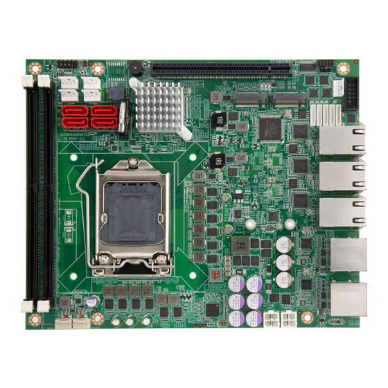
Page 16: Motherboard Internal Diagram - Top Side
Board Overview 2.1 Motherboard Internal Diagram - Top Side ⑱SATA4 SATAPWR 3 ⑯SATA2 ⑳SATAPWR 2 DIMM2 DIMM1 ①SYSFAN1 USB1 SATA4 SATA2 ➊JME1 ②CPUFAN1 ⑲SATAPWR 1 SATAPWR 4 ⑰SATA 3 JBIOS1 ⑮SATA 1 JBIOSROM1 ⑭PCIE1 NGFF1 ⑬NGFF1 ③PWR1 NGFF2 ④PWR2 ⑫NGFF2 ⑪COM5 ⑩COM4 ➋JATMODE1... -
Page 17: Jumper And Connector
Board Overview 2.2 Jumper and Connector Jumper Name Description ➊ Clear CMOS Jumper 2-pin Block ➋ AT/ATX Type Selection 2-pin Block JATMODE1 Connector Name ① System Fan Connector SYSFAN ② CPU Fan Connector CPUFAN ③ DCIN 9~36V Power input Connector PWR1 ④... -
Page 18: Dimensions
Board Overview 2.3 Dimensions 44.9 176.98 6.35 163.83 Unit: mm - 10 -... -
Page 19: Chapter 3 - Installation & Maintenance
Installation & Maintenance Chapter 3 Hardware Installation - 11 -... -
Page 20: Jumpers & Connectors Quick Reference
Installation & Maintenance 3.1 Jumpers & Connectors Quick Reference Jumper Name Description ➊ Clear CMOS Jumper 2-pin Block ➋ AT/ATX Type Selection 2-pin Block JATMODE1 Connector Name ① System Fan Connector SYSFAN ② CPU Fan Connector CPUFAN ③ DCIN 9~36V Power input Connector PWR1 ④... -
Page 21: Jumpers & Connectors Location
Installation & Maintenance 3.2 Jumpers & Connectors Location ⑱SATA4 SATAPWR 3 ⑯SATA2 ⑳SATAPWR 2 DIMM2 DIMM1 ①SYSFAN1 USB1 SATA4 SATA2 ➊JME1 ②CPUFAN1 ⑲SATAPWR 1 SATAPWR 4 ⑰SATA 3 JBIOS1 ⑮SATA 1 JBIOSROM1 ⑭PCIE1 NGFF1 ⑬NGFF1 ③PWR1 NGFF2 ④PWR2 ⑫NGFF2 ⑪COM5 ⑩COM4 ➋JATMODE1 DGP1... -
Page 22: Connectors And Headers
Installation & Maintenance 3.2 Connectors and Headers 3.2.1 Jumpers ➊ JME1 Function: Clear CMOS Selection Jumper Type: 2.00mm pitch, 1x3-pin header Setting: Description Clear CMOS ➋ JATMODE1 Function: AT/ATX Type Selection Jumper Type: onboard 3-pin 2.0 mm header Setting: Description *ATX Note: *Default setting: Keep ATX mode for default setting. - Page 23 Installation & Maintenance 3.2.2 Connectors ① SYSFAN Function: Smart FAN connector Jumper Type: WAFER,4*1,2.54mm,1-WALL,HSG3/4 Pin definition: Description +12V FANIN FANCTL ② CPUFAN Function: Smart FAN connector Jumper Type: WAFER,4*1,2.54mm,1-WALL,HSG3/4 Pin definition: Description +12V FANIN FANCTL ③④ PWR1/PWR2 Function: Power input Jumper Type: ATX-4P,CVILUX,CP-01304130 Pin definition:...
- Page 24 Installation & Maintenance ⑤ JFRT1 Function: Switches and Indicators Jumper Type: 2x5-10P BOX HEADER Pin definition: Description Description HDD_LED+ SYSPWR_LED+ HDD_LED- SYSPWR_LED- PWRBTN RESET ⑥ FNPWR1 Function: FRONT PANEL power connector Jumper Type: 2x5-10P BOX HEADER Pin definition: Description ⑦⑧ COM1, COM2 Function: COM1 /COM2 (RS232\RS422\RS485)
- Page 25 Installation & Maintenance ⑨⑩⑪ COM3~COM5 Function: COM3 /COM4 /COM5 (RS232C) Jumper Type: 1*9P,WAFER-4WALL,ACES,86801-090L Pin definition: Description Description ⑫⑬ NGFF1, NGFF2 Function: M.2 M KEY PCI-E CONNECTOR Jumper Type: NGFF CARD,75P,BLACK,KEY M Pin definition: The pin assignments conform to the industry stan- dard.
- Page 26 Installation & Maintenance ⑲⑳ 21 22 PWROUT1\2\3\4 Function: SATA Power Jumper Type: 1*4P,WAFER-1WALL,TECHBEST,AD04900041152 Pin definition: Description Description +12V USB1 Function: USB 2.0 connector Jumper Type: 2.00mm pitch 2x5(-9)pin wafer connector Pin definition: Description Description USB +5V USB +5V USB- USB- USB+ USB+ - 18 -...
-
Page 27: Chapter 4 - Bios
BIOS Chapter 4 BIOS - 19 -... -
Page 28: Introducing Bios
BIOS 4. Introducing BIOS The BIOS is a program located on a Flash Memory on the motherboard. This program is a bridge between motherboard and operating system. When you start the computer, the BIOS program will gain control. The BIOS first operates an auto-diagnostic test called POST (power on self test) for all the necessary hardware, it detects the entire hardware device and configures the parameters of the hardware synchronization. -
Page 29: Bios Menu Screen
BIOS 4.2 BIOS Menu Screen The following diagram show a general BIOS menu screen: 4.3 Function Keys In the above BIOS Setup main menu of, you can see several options. We will explain these options step by step in the following pages of this chapter, but let us first see a short description of the function keys you may use here: The AMI BIOS provides a Setup utility program for specifying the system config- urations and settings. -
Page 30: Main Menu
BIOS 4.6 Main Menu Main menu screen includes some basic system information. Highlight the item and then use the <+> or <-> and numerical keyboard keys to select the value you want in each item. Setting Description Set the date. Please use [Tab] to switch between data System Date elements. -
Page 31: Advanced Menu
BIOS 4.7 Advanced Menu Setting Description CPU Configuration on page 4.7.1 CPU Configuration Trusted Computing 4.7.2 CPU Trusted Computing on page ACPI Settings 4.7.3 ACPI Settings on page 27 Super IO Configuration 4.7.4 Super IO Configuration on page Hardware Monitor 4.7.5 Hardware Monitor on page PCI Subsystem Settings... - Page 32 BIOS 4.7.1 CPU Configuration Setting Description Number of cores to enable in each processor Active Processor Cores package. Options: All (default), 1~9 ► Enabled (default) for Windows and Linux (OS optimized for Hyper-Threading Technology) and Disabled for other OS (OS not optimized or Hyper-threading Hyper-Threading Technology).
- Page 33 BIOS Enable or Disable Intel virtualization technol- ogy. When enabled, a VMM can utilize the Intel (VMX) Virtualization additional hardware capabilities provide by Vanderpool Technology. Options: Enabled (default) or Disabled ► This item allows more than two frequency ranges to be supported. Intel(R) SpeedStep(tm) The optional settings are: [Disabled];...
- Page 34 BIOS 4.7.2 CPU Trusted Computing Setting Description Enable (default) or Disable BIOS support for security device. O.S. will not show Security De- Security Device Support vice. TCG EFI protocol and INT1A interface will not be available. - 26 -...
- Page 35 BIOS 4.7.3 ACPI Settings Setting Description Enable ACPI Auto Con- Enable or Disable(default) BIOS ACPI Auto figuration configuration. Enable (default) or Disable System ability to Enable Hibernation Hibernate (OS/S4 Sleep State). This option may be not effective with some OS. Select the highest ACPI sleep state the sys- tem will enter when the SUSPEND button is ACPI Sleep State...
- Page 36 BIOS 4.7.4 Super IO Configuration Setting Description Serial Port 1/2/3/4/5 Con- See next page. figuration - 28 -...
- Page 37 BIOS Serial Port 1/2/3/4/5 Configuration Setting Description Serial Port Enable (default) or Disable Serial Port (COM). - 29 -...
- Page 38 BIOS Options for Serial Port 1 Configuration: ► Serial Port:Enable (default) or Disable Serial Port (COM). Options for Serial Port 1 Mode Configuration: Mode Select: RS-232 / RS-422 / RS-485 / RS-422 Termination Resitor / RS-485 Termination Resitor Options for Serial Port 2 Configuration: ►...
- Page 39 BIOS 4.7.5 Hardware Monitor Access this submenu to monitor the hardware status. Setting Description Press [Enter] to make settings for SmartFan CPUFAN SmartFan Function Configuration: SmartFAN Mode / Manual Mode Press [Enter] to make settings for SmartFan SYSFAN SmartFan Function Configuration: SmartFAN Mode / Manual Mode.
- Page 40 BIOS 4.7.6 PCI Subsystem Settings Setting Description Value to be programmed into PCI Latency timer Register. PCI Latency Timer 32/64/96/128/160/192/224/248 PCI Bus Clocks ► Default: 32 PCI Bus Clocks ► Value to be programmed into PCI-X Latency Timer Reg- PCI-X Latency ister.
- Page 41 BIOS 4.7.7 USB Configuration Setting Description Sets legacy USB support. Options: Enabled (default), Disabled and Auto. ► AUTO option disables legacy support if no USB Legacy USB Support devices are connected. Disable option will keep USB devices available only for EFI applications. Enable (default) or Disable XHCI Hand-off This is a workaround for OSes without XHCI hand- XHCI Hand-off...
- Page 42 BIOS Use this item to set the time-out value for control, bulk, USB Transfer time- and interrupt transfers. Options available are: 1 sec, 5 sec, 10 sec, 20 sec (default) Use this item to set USB mass storage device start unit Device reset time- command time-out.
- Page 43 BIOS 4.7.8 CSM Configuration Setting Description CSM Support Enable (default) or Disable CSM Support. Control the Legacy/UEFI ROMs priority. Boot option filter Options: UEFI and Legacy (default), Legacy only ► and UEFI only Control the execution of UEFI and Legacy PXE OpROM Network Options: Do not lauch (default), UEFI and Legacy ►...
- Page 44 BIOS 4.7.9 NVMe Configuration Access this submenu to view the NVMe controller and driver information. - 36 -...
-
Page 45: Chipset
BIOS 4.8 Chipset Setting Description Access this submenu to view the memory con- Memory Configuration figuration. - 37 -... - Page 46 BIOS Primary Display ► Options are: Auto(default), IGFX, PEG, and PCI. Internal Graphics ► Options are: Auto(default), Disabled, Enabled GTT Size ► Options are: 2MB/4MB/8MB(default) Graphic Configuration Aperture Size ► Options are: 128MB/256MB(default)/512MB/1 024MB/2048MB DVMT Pre-Allocated ► 32M is the default. DVMT Total Gfx Mem ►...
- Page 47 BIOS VT-d Enable (default) or Disable VT-d function Enable or Disable (default) Above 4GB Above 4GB MMIO BIOS MmemoryMapped BIOS assignment. This is assignment automatically enabled when Aperture Size is set to 2048MB. See PCH-IO Configuration PCI Express Configuration See 4.8.1 PCI Express Configuration on page SATA And RST...
-
Page 48: Pci Express Configuration
BIOS 4.8.1 PCI Express Configuration Setting Description PCIE1, 2 Enable (default) or disable PCIE1/2. Disable or set the ASPM level. Force L0s will force all inks to L0s state. “Auto” will allow BIOS to auto ASPM configure.”Disable” will disable ASPM. Options: Disabled (default), L0s, L1, L0sL1 and ►... -
Page 49: Security
BIOS 4.9 Security Setting Description To set up an administrator password: 1. Select Administrator Password. The screen then pops up an Create New Password Administrator dialog. Password 2. Enter your desired password that is no less than 3 char- acters and no more than 20 characters. 3. -
Page 50: Boot
BIOS 4.10 Boot Setting Description Select the keyboard NumLock state. Boot NumLock State Options: On (default) and Off. ► Enable or Disable(default) Quiet Boot option. Quiet Boot Boot Option Priority Set the system boot priorities. Hard Drive BBS Priori- BBS means “BIOS Boot Specification”. ties Sets the order of the legacy devices in this group. -
Page 51: Save & Exit
BIOS 4.11 Save & Exit Setting Description Exit system setup after saving the changes. Save Changes and Enter the item and then a dialog box pops up: ► Exit Save configuration and exit? (Yes/ No) Exit system setup without saving the changes. Discard Changes and Enter the item and then a dialog box pops up: ►...
Need help?
Do you have a question about the ITX-i92QA and is the answer not in the manual?
Questions and answers