Table of Contents
Advertisement
Advertisement
Table of Contents

Related Manuals for Arbor Technology MB-i67Q0


Summary of Contents for Arbor Technology MB-i67Q0
- Page 1 MB-i67Q0 Micro-ATX Industrial Motherboard User’s Manual Version 1.0 2012.07 - 1 -...
- Page 2 This page is intentionally left blank. - 2 -...
-
Page 3: Table Of Contents
Index Table of Contents Chapter 1 - Introduction ................1 1.1 Copyright Notice ..............2 1.2 Declaration of Conformity ............. 2 1.3 About This User’s Manual ............. 4 1.4 Warning ................... 4 1.5 Replacing the Lithium Battery ..........4 1.6 Technical Support ..............5 1.7 Warranty .................. - Page 4 Index DVI1: COM1 & DVI-I ..............23 KBMUSB1: PS/2 Keyboard and USB Stacked Connector .. 24 JDIO1: Digital I/O Connector ..........24 2.3 The Installation Paths of CD Driver ........25 Chapter 3 - BIOS ..................27 3.1 BIOS Main Setup ..............28 3.2 Advanced Settings ...............
-
Page 5: Chapter 1 Introduction
Introduction Chapter 1 Introduction Chapter 1 - Introduction - 1 -... -
Page 6: Copyright Notice
Introduction 1.1 Copyright Notice All Rights Reserved. The information in this document is subject to change without prior notice in order to improve the reliability, design and function. It does not represent a commitment on the part of the manufacturer. Under no circumstances will the manufacturer be liable for any direct, indirect, special, incidental, or consequential damages arising from the use or inability to use the product or documentation, even if advised of the possibility of such... - Page 7 -- Consult the dealer or an experienced radio/TV technician for help. RoHS ARBOR Technology Corp. certifies that all components in its products are in compliance and conform to the European Union’s Restriction of Use of Haz- ardous Substances in Electrical and Electronic Equipment (RoHS) Directive 2002/95/EC.
-
Page 8: About This User's Manual
Introduction 1.3 About This User’s Manual This user’s manual provides general information and installation instructions about the product. This User’s Manual is intended for experienced users and integrators with hardware knowledge of personal computers. If you are not sure about any description in this booklet. please consult your vendor before further handling. -
Page 9: Technical Support
Introduction 1.6 Technical Support If you have any technical difficulties, please do not hesitate to call or e-mail our customer service. http://www.arbor.com.tw E-mail:info@arbor.com.tw 1.7 Warranty This product is warranted to be in good working order for a period of two years from the date of purchase. -
Page 10: Packing List
Introduction 1.8 Packing List Before you begin installing your single board, please make sure that the following materials have been shipped: 1 x MB-i67Q0 Industrial Motherboard 1 x Driver CD 1 x Quick Installation Guide 1 x I/O Bracket If any of the above items is damaged or missing, contact your vendor immediately. -
Page 11: Recommended Cpu List
Introduction 1.10 Recommended CPU List i7-2600 3.4GHz Core™ Processor i5-2400 3.1GHz Core™ Processor i3-2120 3.3GHz Core™ Processor G850 2.9GHz Pentium Dual Core Processor ® G540 2.5GHz Celeron Dual Core Processor ® 1.11 Specifications Form Factor Micro-ATX Industrial Motherboard Support Intel® Core™ i7/i5/i3/Pentium®/Celeron® processors in LGA1155 socket Intel ®... - Page 12 Introduction 1 x PCIe x16 slot 1 x PCIe x1 slot Expansion Bus 1 x PCIe x4 interface in x8 slot 1 x PCI slot Universal Serial Bus 14 x USB 2.0 ports Watchdog Timer 1~255 levels reset Dimension (L x W) 244 x 244 mm (9.6”...
-
Page 13: Board Dimensions
Introduction 1.12 Board Dimensions 229.87 163.83 6.35 209.55 243.84 Unit: mm 9.76 42.4 75.05 96.91 118.38 137.38 - 9 -... -
Page 14: Installing The Cpu
Introduction 1.13 Installing the CPU The LGA1155 processor socket comes with a lever to secure the processor. Please refer to the pictures step by step as below and note that the cover of the LGA1155 socket must always be installed during transportation to avoid damage to the socket. -
Page 15: Installing The Memory
Introduction 1.14 Installing the Memory To install the Memory module, locate the Memory DIMM slot on the board and perform as below: 1. Hold the Memory module so that the key of the Memory module align with those on the Memory DIMM slot. 2. - Page 16 This page is intentionally left blank. - 12 -...
-
Page 17: Chapter 2 Installation
Installation Chapter 2 Installation Chapter 2 - Installation - 13 -... -
Page 18: Block Diagram
Installation 2.1 Block Diagram MB-i67Q0 Sandy Bridge Q67 platform Embedded Micro ATX Motherboard VCore Power DC to DC Intel Ivy Dual Channel DDR3 DDR3 DIMM /Sandy DDR3 DIMM 1066/1333MHz Bridge LGA1155 Dual Channel DDR3 PCIex16 DDR3 DIMM PCIe x16 slot... -
Page 19: Jumpers And Connectors Location
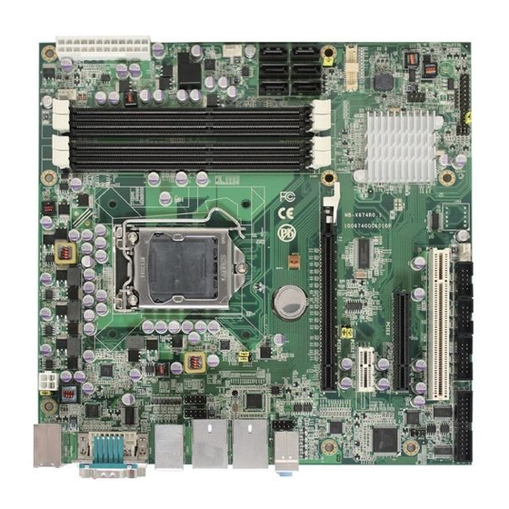
Installation 2.2 Jumpers and Connectors Location SATA2 SATA1 SATA3 SATA4 SATA5 SATA6 FAN2 ATX1 JBIOS1 JFRT1 FAN1 JP12 JDIO1 JP16 PCI1 FAN3 PCIE3 COM3 COM2 COM4 ATX12V1 JKBMS1 PCIE1 PCIE2 LPT1 KBMUSB1 AUDIO3 DVI1 USB2 USB3 LAN1 LAN2 AUDIO1 JRS2 USB1 Line in/out/Mic KB/MS... -
Page 20: Jumpers
Installation Jumpers JBIOS1: BIOS Update Port (1) Connector type: 2.54mm pitch 2x4-pin header. Pin Desc. Pin Desc. 3.3V CS0# JP12: Intel ME Mode Selection (2) Connector type: 2.54mm pitch 1x3-pin header. Pin Description 1-2 Disable ME 2-3 Enable ME (Default) Note: The jumper can only be used to clear COMS data instead of RTC time. -
Page 21: Jrs2: Com4 Rs-232/422/485 Selection
Installation JRS2: COM4 RS-232/422/485 Selection (6) Connector type: 2.00mm pitch 2x3-pin header. RS-232 Mode RS-422 RS-485 (Default) Short Open Open Open Short Open Open Open Short JKBMS1: KB/MS Power Source Selection (7) Connector type: 2.54mm pitch 1x3-pin header. Pin Voltage 1-2 5V (Default) 2-3 5VSB Connectors... -
Page 22: Atx1: Atx Power Connector
Installation ATX1: ATX Power Connector (10) Connector type: 24-pin ATX Power Supply connector. Pin Desc. Pin Desc. +3.3V +3.3V +3.3V -12V PS-ON PW-OK +5VSB 10 +12V 11 +12V 12 +3.3V SATA1~6: Serial ATA Connectors (12~17) Connector type: lockable SATA connectors with housing. SATA1~2 support 600MB/s HDD transfer rate. -
Page 23: Jfrt1: Switches And Indicators
Installation JFRT1: Switches and Indicators (18) It provides light indication of the computer activities and switches to change the computer status. Connector type: 2.54mm pitch 2x8 pin header. Power LED Power Button System Reset HDD LED Speaker+ SMBus Speaker- Pin Description Pin Description LED- LED+ PWRBTN-... -
Page 24: Com4: Rs-232/422/485 Connector
Installation COM4: RS-232/422/485 Connector (22) Connector type: 2.54mm pitch 2x7-pin header. Desc. Desc. RS-232 422TX+485+ 422TX-485- 13 14 RS-485/422 422RX+ 422RX- LPT1: Parallel Port (23) Connector type: 2.54mm pitch 2x13-pin box header. Desc. Desc. #STROBE #AUTO FEED DATA0 #ERROR DATA1 #INITIALIZE DATA2 #SELECT INPUT... -
Page 25: Audio3: Aux Audio Connector
Installation AUDIO3: Aux Audio Connector (24) Connector type: 2.54mm pitch 2x5-pin box header. Pin Description Pin Description MIC2_L MIC2_R PRESENCE LINE2_R MIC2_JD 9 10 SENSE LINE2_L LINE2_JD AUDIO1: Audio Interface Port (25) Line in Connector type: 3 x 3.5mm phone jack stacked. Audio Jack Description Line out Blue... -
Page 26: Lan1~2: Rj-45+Usb Stacked Connectors
Installation LAN1~2: RJ-45+USB Stacked Connectors (27, 26) Connector type: RJ-45 connector with LED/Stacked USB type A connector. LAN (RJ-45) Desc. Desc. TCT VCC A10 RCT GND LED1 Y- A12 LED1 Y+ LED2 G-O+ A14 LED2 G+O- USB (USB type A connector) USBD1- USBD2- USBD1+... -
Page 27: Dvi1: Com1 & Dvi-I
Installation DVI1: COM1 & DVI-I (31) Connector type: Male type D-SUB 9-pin connector + female type DVI-I con- nector. COM1 C1 C2 DVI-I C3 C4 DVI-I Pin Desc. Pin Desc. TX2- 13 TX3+ TX2+ 14 +5V/50mA TX2/4GND 15 GND TX4- 16 HTPLG TX4+ 17 TX0-... -
Page 28: Kbmusb1: Ps/2 Keyboard And Usb Stacked Connector
Installation KBMUSB1: PS/2 Keyboard and USB Stacked Connector (32) Connector type: 6-pin Mini-DIN/Stacked USB type A connector. Keyboard (Purple) MS_CLK KB_CLK KB_GND KB_VCC MS_DAT KB_DAT JDIO1: Digital I/O Connector (33) Supports 16-bit programmable Digital Input/Output Connector type: 2.00mm pitch 2x10-pin headers Desc. -
Page 29: The Installation Paths Of Cd Driver
Installation 2.3 The Installation Paths of CD Driver Windows XP Driver Path CHIPSET \CHIPSET\INF 9.2.0.1021 NET Framework \NET Framework\NET Framework 3.5 \ME\MEI_allOS_7.1.13.1088 GRAPHICS \GRAPHICS\INTEL_2K_XP_32\5391 \ETHERNET\INTEL\82583V\WINXP_32_Ver16 \ETHERNET\INTEL\82583V\WINXP_64_Ver16 AUDIO \AUDIO\REALTEK_HD\WDM_R267 Windows 7 Driver Path CHIPSET \CHIPSET\INF 9.2.0.1021 \ME\MEI_allOS_7.1.13.1088 GRAPHICS \GRAPHICS\Win7Vista_15221 \ETHERNET\INTEL\82583V\WIN7_32_Ver16 \ETHERNET\INTEL\82583V\WIN7_64_Ver16 AUDIO \AUDIO\REALTEK_HD\Vista_Win7_R262 - 25 -... - Page 30 This page is intentionally left blank. - 26 -...
-
Page 31: Chapter 3 - Bios
BIOS Chapter 3 BIOS Chapter 3 - BIOS - 27 -... -
Page 32: Bios Main Setup
BIOS 3.1 BIOS Main Setup The AMI BIOS provides a setup utility program for specifying the system configurations and settings which are stored in the BIOS ROM of the system. When you turn on the computer, the AMI BIOS is immediately activated. After you have entered the setup utility, use the left/right arrow keys to highlight a particular configuration screen from the top menu bar or use the down arrow key to access and configure the information below. -
Page 33: Advanced Settings
BIOS Set the system date. Note that the ‘Day’ automatically changes when you set the date. The date format is: Day : Sun to Sat Month : 1 to 12 Date : 1 to 31 Year : 1999 to 2099 System Time Set the system time. -
Page 34: Acpi Settings
BIOS 3.2.1 ACPI Settings Enable ACPI Auto Configuration This item allows you to enable/disable ACPI (Advanced Configuration and Power Interface) Auto Configuration. Setting: Disabled (Default), Enabled. Enable Hibernation Enable/Disable system ability to Hibernation (OS/S4 Sleep State). This option may be not effective with some OS. Setting: Enabled (Default), Disabled ACPI Sleep State Select the highest ACPI sleep state the system will enter when the SUSPEND... -
Page 35: Cpu Configuration
BIOS 3.2.2 CPU Configuration The CPU Configuration setup screen varies depending on the installed processor. Hyper-threading This item is used to enable or disable the processor’s Hyper-threading feature. Enabled for Windows XP and Linux (OS optimized for Hyper-threading Technology) and disabled for other OS (OS not optimized for Hyper-threading Technology). -
Page 36: Hardware Prefetcher
BIOS Hardware Prefetcher To turn on/off the Mid Level Cache (L2) streamer prefetcher. Adjacent Cache Line Prefetch To turn of/off prefetching of adjacent cache lines. Intel Virtualization Technology When enabled, a VMM can utilize the additional hardware capabilities pro- vided by Vanderpool Technology. Power Technology Enable the power management features. -
Page 37: Sata Configuration
BIOS 3.2.3 SATA Configuration It allows you to select the operation mode for SATA controller. SATA Mode The choice: Disable; IDE Mode (Default), AHCI Mode, RAID Mode IDE: Set the Serial ATA drives as Parallel ATA storage devices. AHCI: Allow the Serial ATA devices to use AHCI (Advanced Host Controller Interface). -
Page 38: Intel Igd Swsci Opregion
BIOS 3.2.4 Intel IGD SWSCI OpRegion DVMT Mode Select Select DVMT Mode used by Internal Graphic Device. DVMT/FIXED Memory Select DVMT/FIXED Mode Memory size used by Internal Graphic Device. IGD - Boot Type Select the Video Device which will be activated during POST. This has no effect if external graphics present. -
Page 39: Intel Txt (Lt) Configuration
BIOS 3.2.5 Intel TXT (LT) Configuration - 35 -... -
Page 40: Usb Configuration
BIOS 3.2.6 USB Configuration Legacy USB Support Enable option supports legacy USB. AUTO option disables legacy support if no USB devices are connected. DISABLE option will keep USB devices available only for EFI applications. EHCI Hand-off Allow you to enable support for operating systems without an EHCI hand-off feature. -
Page 41: Super Io Configuration
BIOS 3.2.7 Super IO Configuration You can use this item to set up or change the Super IO configuration for paral- lel ports. - 37 -... -
Page 42: Parallel Port Configuration
BIOS Parallel Port Configuration Parallel Port Enable/Disable Parallel Port (LPT/LPTE). Change Settings Select an optimal setting for Super IO device. Device Mode Change the Printer Port mode. - 38 -... -
Page 43: H/W Monitor
BIOS 3.2.8 H/W Monitor CPU/SYS Temperature Limit of Highest Allow you to set highest temperature. CPU/SYS Temperature Limit of Lowest Allow you to set lowest temperature. SYSF1~3 Highest Setting Allow you to set highest speed value. SYSF1~3 Second Setting Allow you to set second speed value. SYSF1~3 Lowest Setting Allow you to set lowest speed value. -
Page 44: Second Super Io Configuration
BIOS 3.2.9 Second Super IO Configuration You can use this item to set up or change the Second Super IO configuration for serial ports. Serial Port 1~4 Configuration - 40 -... -
Page 45: Amt Configuration
BIOS Serial Port Enable/Disable Serial Port (COM). Change Settings Select an optimal setting for Super IO device. COM4 RS485 AutoFlow (only in Serial Port 4 Configuration) The choice: Enabled, Disabled (Default) 3.2.10 AMT Configuration Enable/Disable AMT help. Unconfigure AMT/ME Unconfigure AMT/ME without password. WatchDog Timer Enable/Disable WatchDog Timer. -
Page 46: Serial Port Console Redirection
BIOS 3.2.11 Serial Port Console Redirection Console Redirection Enable/Disable Console Redirection. Console Redirection Settings The settings specify how the host computer and the remote computer (which the user is using) will exchange data. Both computers should have the same or compatible settings. - 42 -... -
Page 47: Terminal Type
BIOS Out-of-Band Mgmt Port Microsoft Windows Emergency Management Services (EMS) allows for remote management of a Windows Server OS through a serial port. Terminal Type VT-UTF8 is the preferred terminal type for out-of-band management. The next best choice is VT100+ and then VT100. See above, in Console Redi- rection Settings page, for more Help with Terminal Type/Emulation. -
Page 48: Chipset
BIOS 3.3 Chipset This section allows you to configure and improve your system; also, set up some system features according to your preference. - 44 -... -
Page 49: North Bridge
BIOS 3.3.1 North Bridge Low MMIO Align Low MMIO resources align at 64MB/1024MB. DMI Gen2 Enable/Disable DMI Gen2. Initate Graphic Adapter Select which graphics controller to use as the primary boot device. IGD Memory Set IGD share memory size. Render Standby Enable/Disable Render Standby by Internet Graphics Device. -
Page 50: South Bridge
BIOS PCI Express Port Set PCI Express. PEG Force Gen1 Set PCI Express Port Force Gen1. Detect Non-Compliance Device Detect Non-Compliance PCI Express Device in PEG. MRC Message Print Print Memory initialize message. 3.3.2 South Bridge SB Chipset Configuration Enable/Disable GbE control PME in S5. Restore AC Power Loss Specify what state to go to when power is re-applied after a power failure (G3 state). - Page 51 BIOS PCI Express Ports Configuration USB Configuration - 47 -...
-
Page 52: Me Subsystem
BIOS All USB Devices Enable/Disable all USB devices. EHCI controller 1/2 Enable/Disable USB 2.0 (EHCI) support. 3.3.3 ME Subsystem ME Subsystem Enable/Disable the Intel ME subsystem. ® ME Temporary Disable Configure ME Temporary Disable. End of Post Message Enable/Disable the end of post message of the ME Subsystem. Execute MEBx Enable/Disable the Intel®... - Page 53 BIOS Integrated Clock Chip Configuration ICC Enable Enable/Disable integrated clock chip. - 49 -...
-
Page 54: Boot Settings
BIOS 3.4 Boot Settings The Boot menu items allow you to change the system boot options. Boot Configuration Bootup NumLock State This setting determines whether the Num Lock key should be activated at boot up. Quiet Boot This allows you to select the screen display when the system boots. - 50 -... -
Page 55: Security
BIOS 3.5 Security Administrator Password Use the Administrator Password to set or change a administrator password. ENTER PASSWORD Type the password, up to eight characters in length, and press <Enter>. The password typed now will clear any previously entered password from CMOS memory. -
Page 56: Save & Exit
BIOS PASSWORD DISABLED When a password has been enabled, you will be prompted to enter it every time you try to enter Setup. This prevents an unauthorized person from changing any part of your system configuration. Additionally, when a password is enabled, you can also require the BIOS to request a password every time your system is rebooted. -
Page 57: Discard Changes And Exit
BIOS Save Changes and Reset Pressing <Enter> on this item and it asks for confirmation: Save configuration changes and exit setup? Pressing <OK> stores the selection made in the menus in CMOS - a special section of memory that stays on after you turn your system off. The next time you boot your computer, the BIOS configures your system according to the Setup selections stored in CMOS. -
Page 58: Ami Bios Checkpoints
BIOS 3.7 AMI BIOS Checkpoints 3.7.1 Checkpoint Ranges Status Code Range Description 0x01 – 0x0B SEC execution 0x0C – 0x0F SEC errors PEI execution up to and including memory 0x10 – 0x2F detection 0x30 – 0x4F PEI execution after memory detection 0x50 –... -
Page 59: Standard Checkpoints
BIOS 3.7.2 Standard Checkpoints SEC Phase Status Code Description 0x00 Not used Progress Codes 0x01 Power on. Reset type detection (soft/hard). 0x02 AP initialization before microcode loading 0x03 North Bridge initialization before microcode loading 0x04 South Bridge initialization before microcode loading 0x05 OEM initialization before microcode loading 0x06... - Page 60 BIOS PEI Phase Status Code Description Progress Codes 0x10 PEI Core is started 0x11 Pre-memory CPU initialization is started 0x12 Pre-memory CPU initialization (CPU module specific) 0x13 Pre-memory CPU initialization (CPU module specific) 0x14 Pre-memory CPU initialization (CPU module specific) 0x15 Pre-memory North Bridge initialization is started Pre-Memory North Bridge initialization (North Bridge...
- Page 61 BIOS 0x32 CPU post-memory initialization is started 0x33 CPU post-memory initialization. Cache initialization CPU post-memory initialization. Application Processor(s) 0x34 (AP) initialization CPU post-memory initialization. Boot Strap Processor 0x35 (BSP) selection CPU post-memory initialization. System Management 0x36 Mode (SMM) initialization 0x37 Post-Memory North Bridge initialization is started Post-Memory North Bridge initialization (North Bridge 0x38...
- Page 62 BIOS 0x55 Memory not installed 0x56 Invalid CPU type or Speed 0x57 CPU mismatch 0x58 CPU self test failed or possible CPU cache error CPU micro-code is not found or micro-code update is 0x59 failed 0x5A Internal CPU error 0x5B reset PPI is not available 0x5C-0x5F Reserved for future AMI error codes...
- Page 63 BIOS 0xF9 Recovery capsule is not found 0xFA Invalid recovery capsule 0xFB – 0xFF Reserved for future AMI error codes DXE Phase Status Code Description 0x60 DXE Core is started 0x61 NVRAM initialization 0x62 Installation of the South Bridge Runtime Services 0x63 CPU DXE initialization is started 0x64...
- Page 64 BIOS South Bridge DXE Initialization (South Bridge module 0x74 specific) South Bridge DXE Initialization (South Bridge module 0x75 specific) South Bridge DXE Initialization (South Bridge module 0x76 specific) South Bridge DXE Initialization (South Bridge module 0x77 specific) 0x78 ACPI module initialization 0x79 CSM initialization 0x7A –...
- Page 65 BIOS 0xA4 SCSI initialization is started 0xA5 SCSI Reset 0xA6 SCSI Detect 0xA7 SCSI Enable 0xA8 Setup Verifying Password 0xA9 Start of Setup 0xAA Reserved for ASL (see ASL Status Codes section below) 0xAB Setup Input Wait 0xAC Reserved for ASL (see ASL Status Codes section below) 0xAD Ready To Boot event 0xAE...
- Page 66 BIOS 0xD7 No Console Input Devices are found 0xD8 Invalid password 0xD9 Error loading Boot Option (LoadImage returned error) 0xDA Boot Option is failed (StartImage returned error) 0xDB Flash update is failed 0xDC Reset protocol is not available ACPI/ASL Checkpoints Status Code Description 0x01...
-
Page 67: Appendix
Appendix Appendix Appendix - 63 -... -
Page 68: Appendix A: I/O Port Address Map
Appendix Appendix A: I/O Port Address Map Each peripheral device in the system is assigned a set of I/O port addresses which also becomes the identity of the device. The following table lists the I/O port addresses used. Address Device Description 00000000-0000000F Direct memory access controller 00000000-000003AF... - Page 69 Appendix 000000E0-000000EF Motherboard resources 000000F0-000000FF Numeric data processor 00000170-00000177 ATA Channel 1 000001F0-000001F7 ATA Channel 0 00000290-0000029F Motherboard resources 000002E8-000002EF Communications Port (COM4) 000002F8-000002FF Communications Port (COM2) 00000376-00000376 ATA Channel 1 00000378-0000037F Printer Port (LPT1) 000003B0-000003BB Intel(R) HD Graphics Family 000003B0-000003DF PCI bus 000003C0-000003DF...
- Page 70 Appendix 0000F0A0-0000F0A3 Intel(R) 6 Series/C200 Series Chipset Family 2 port 0000F0B0-0000F0B7 Intel(R) 6 Series/C200 Series Chipset Family 2 port 0000F0C0-0000F0C3 Intel(R) 6 Series/C200 Series Chipset Family 2 port 0000F0D0-0000F0D7 Intel(R) 6 Series/C200 Series Chipset Family 2 port 0000F0E0-0000F0EF Intel(R) 6 Series/C200 Series Chipset Family 4 port Serial 0000F0F0-0000F0FF ntel(R) 6 Series/C200 Series Chipset Family 4...
-
Page 71: Appendix B: Interrupt Request Lines (Irq)
Appendix Appendix B: Interrupt Request Lines (IRQ) Peripheral devices use interrupt request lines to notify CPU for the service required. The following table shows the IRQ used by the devices on board. Level Function IRQ 9 Microsoft ACPI-Compliant System IRQ 16 Intel(R) HD Graphics IRQ 16 Intel(R) Management Engine Interface... -
Page 72: Appendix C: Bios Memory Mapping
Appendix IRQ 3 Communications Port (COM4) IRQ 0 System timer IRQ 8 System CMOS/real time clock IRQ 13 Numeric data processor IRQ 15 Secondary IDE Channel IRQ 10 Intel(R) 6 Series/C200 Series Chipset Family SMBus Controller - 1C22 Appendix C: BIOS Memory Mapping Address Device Description 000A0000-000BFFFF... - Page 73 Appendix FE628000-FE628FFF Intel(R) Active Management Technology - SOL (COM5) FE629000-FE62900F Intel(R) Management Engine Interface FEC00000-FECFFFFF System board FED00000-FED003FF High Precision Event Timer, HPET FED08000-FED08FFF System board FED10000-FED19FFF System board FED1C000-FED1FFFF System board FED20000-FED3FFFF System board FED90000-FED93FFF System board FEE00000-FEE0FFFF System board FF000000-FFFFFFFF System board - 69 -...
-
Page 74: Appendix D: Watchdog Timer (Wdt) Setting
Appendix Appendix D: Watchdog Timer (WDT) Setting WDT is widely used for industry application to monitoring the activity of CPU. Application software depends on its requirement to trigger WDT with ad- equate timer setting. Before WDT time out, the functional normal system will reload the WDT. - Page 75 Appendix outportb(0x2e, 0x07); /* point to logical device */ outportb(0x2e+1, 0x07); /* select logical device 7 */ outportb(0x2e, 0xf5); /* select offset f5h */ outportb(0x2e+1, 0x40); /* set bit5 = 1 to clear bit5 */ outportb(0x2e, 0xf0); /* select offset f0h */ outportb(0x2e+1, 0x81);...
Need help?
Do you have a question about the MB-i67Q0 and is the answer not in the manual?
Questions and answers