Table of Contents
Advertisement
Quick Links
SERVICE MANUAL
AH-13-01.3
FEBRUARY - 2016
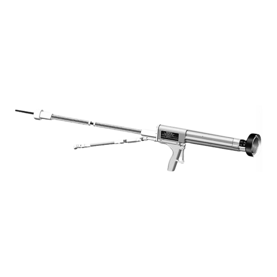
NO. 2 PROCESS HANDGUN
ELECTRIC MOTOR VERSION
MODEL: 19372
IMPORTANT:
Before using this equipment,
carefully read SAFETY PRECAUTIONS, starting
on page 1, and all instructions in this manual.
Keep this Service Manual for future reference.
Service Manual Price:
Ransburg
$50.00 (U.S.)
Advertisement
Table of Contents

Related Manuals for Ransburg 19372


Summary of Contents for Ransburg 19372
- Page 1 Ransburg AH-13-01.3 FEBRUARY - 2016 NO. 2 PROCESS HANDGUN ELECTRIC MOTOR VERSION MODEL: 19372 IMPORTANT: Before using this equipment, carefully read SAFETY PRECAUTIONS, starting on page 1, and all instructions in this manual. Keep this Service Manual for future reference.
- Page 2 No. 2 Process Electric Motor Version - MANUAL CHANGES NOTE: This manual has been changed from revision AH-13-01.2 to revision AH-13-01.3. Reasons for this change are noted under “Manual Change Summary” on page 56 of this manual. AH-13-01.3...
-
Page 3: Table Of Contents
No. 2 Process Electric Motor Version - CONTENTS CONTENTS PAGE SAFETY: SAFETY PRECAUTIONS ......................1 HAZARDS / SAFEGUARDS ..................... 2-5 INTRODUCTION: GENERAL DESCRIPTION ....................... 6 SPECIFICATIONS ........................7 GUN AND POWER SUPPLY FEATURES ................8 INSTALLATION: 9-14 PRE-INSTALLATION REQUIREMENTS .................. 9 SAFEGUARDS ......................... - Page 4 CONTENTS (Cont.) PAGE PARTS IDENTIFICATION: 42-54 19372-AAU PARTS BREAKOUT ....................42 CABLE / MOTOR PARTS LIST ....................43 7233-00 HANDLE PARTS LIST....................44 NEEDLE VALVE ASSEMBLY PARTS LIST ................45 BARREL PARTS LIST ......................46 8340-XX FLUID HOSE PARTS AND ASSEMBLIES ..............47 FEED TUBE PARTS .........................
-
Page 5: Safety
Safety Section in this manual and understand all of the technical and safety litera- the Ransburg safety literature therein iden- ture for your Ransburg products. This manual tified. contains information that is important for you to know and understand. This information relates to †... -
Page 6: Hazards / Safeguards
No. 2 Process Electric Motor Version - SAFETY HAZARD SAFEGUARDS AREA Tells what the hazard is. Tells how to avoid the hazard. Tells where hazards may occur. Spray Area Fire Hazard Fire extinguishing equipment must be present in the spray area and tested periodically. Improper or inadequate operation and maintenance Spray areas must be kept clean to prevent the... - Page 7 No. 2 Process Electric Motor Version - SAFETY AREA HAZARD SAFEGUARDS Tells where hazards Tells what the hazard is. Tells how to avoid the hazard. may occur. Explosion Hazard Spray Area Improper or inadequate oper- Electrostatic arcing must be prevented. Safe ation and maintenance proce- sparking distance must be maintained be- dures will cause a fire hazard.
- Page 8 No. 2 Process Electric Motor Version - SAFETY AREA HAZARD SAFEGUARDS Tells where hazards Tells what the hazard is. Tells how to avoid the hazard. may occur. Spray Area / Electrical Discharge High Voltage Parts being sprayed and operators in the spray There is a high voltage device Equipment area must be properly grounded.
- Page 9 No. 2 Process Electric Motor Version - SAFETY AREA HAZARD SAFEGUARDS Tells where hazards Tells what the hazard is. Tells how to avoid the hazard. may occur. Electrical Discharge Electrical Equipment Unless specifically approved for use in hazard- High voltage equipment is uti- ous locations, the power supply, control cabinet, lized in the process.
-
Page 10: Introduction
Supply, the High Voltage Cable, and Fluid Hose. bell when the gun is triggered. There, the fluid This unit contains the 19372-XX No. 2 handgun travels across the face of the rotating bell and electric motor version and the 80102-21X 9060 is charged. -
Page 11: Specifications
No. 2 Process Electric Motor Version - INTRODUCTION SPECIFICATIONS Environmental/Physical Mechanical Length: 508 cm (20 inches) Fluid Input Pressure: 3.45 bar (50psig) Air Input Pressure: 6.90 bar (100 psig) Weight: 1588 g (56 ounces) Fluid Delivery Rate: (maximum) 2-3/4” Bell: Electrical 75 cc/minute Rate:... -
Page 12: Gun And Power Supply Features
No. 2 Process Electric Motor Version - INTRODUCTION Figure 1: Gun Features / Model 19372-XX MODEL 19372 -XX GUN FEATURES Description Item Description Item Handle Assembly Drive Shaft and Seal Trigger Barrel Trigger Adjustment On-Off Switch Resistor Housing Cable/Electric Motor Assembly... -
Page 13: Installation
No. 2 Process Electric Motor Version - INSTALLATION INSTALLATION PRE-INSTALLATION The following guidelines can be used: REQUIREMENTS It is highly recommended, whenever possible, • that ALL electronic components or equipment 1. Provide approved electrical wiring to the power be removed from the spray area. This includes supply. -
Page 14: Power Supply
If the literature is not 5. Attach the female nut of the high voltage ca- available, contact your local Ransburg Distributor ble to the male threads of the connection of the where the equipment was purchased. - Page 15 Item # Description 9060 Power Supply 80102-21X Connected to True Earth Ground High Voltage Cable Connection to Power Supply 19372 -XX #2 Electric Motor Applicator Earth grounded regulated paint supply 76938-02 Inline Fluid Filter 8340-25 Fluid Hose 7244-00 Adapter 9/16-18 LH (M) to 3/8-18 NPSM(F)
-
Page 16: Fluid Fitting Installation Procedure
No. 2 Process Electric Motor Version - INSTALLATION INSTALLATION FEED TUBE, BELL, BRUSH 1. Install the proper feed tube into the opening in the applicator. See figure 6. Position the tube at approximately as shown in the figure. 2. Insert the 3695-00 (item 2) brush into the bar- rel. -
Page 17: Accessory Installation
No. 2 Process Electric Motor Version - INSTALLATION ACCESSORY INSTALLATION W A R N I N G Included with the unit are two accessory items: † Replacing the plastic set screw with one • Bell cleaning can and the gun holder. of conductive material (metal) will cause a hazardous condition to exist, capable of pro- W A R N I N G... -
Page 18: No. 2 Handgun Brush Positioning And Wear
No. 2 Process Electric Motor Version - INSTALLATION NO. 2 HANDGUN BRUSH The brush should normally have a slight curve to the arm. The more pressure applied the lesser POSITIONING AND WEAR the curve (see Figure 4). The tip of the brush (Refer to Figure 9) assembly must be inspected prior to each use for wear. -
Page 19: Paint
Paint test equipment such as the test assembly (76652-03) for testing paint elec- trical resistivity, may be purchased through your Ransburg distributor. (See “Paint and Solvent Specifications” in the “Appendix” section of this service manual.) Most paint suppliers may be of assistance in pre-adjusting the paint for proper electrostatic sprayability. -
Page 20: Operation
No. 2 Process Electric Motor Version - OPERATION OPERATION PROCEDURES 4. Turn the 9060 power “ON-OFF” switch on the front panel to the “ON” position as shown in Fig- ure 12. The unit will power up, but high voltage Prior to operating the No. 2 Handgun, ensure that will not be on at this point. -
Page 21: Operations Near Computers Or Other Electronic Devices
(See Ransburg 1. The No. 2 Electric Process Handgun is not manual “No. 2 Handgun Spray Techniques”.) electro-magnetic. -
Page 22: Shutdown
In view of the above unknown and possible un- coating. See Service Instruction “Solvent controlled conditions, Ransburg does not recom- Effects on #2 Handgun Bell / Brush Wear” mend the electrostatic spray painting of computer and “Paint and Solvent Specifications”... -
Page 23: Color Change
No. 2 Process Electric Motor Version - OPERATION COLOR CHANGE 3. Remove and clean the bell (follow the steps under “Shutdown” in the “Operation” section). 4. Place the gun (bell angled down) on the gun If the gun is to be flushed with solvent between support rack to prevent solvent and paint from colors (as when switching between two incom- getting into the unit. -
Page 24: Gun Electrical Output
Power Supply Microampmeter until there is no evidence of paint in the stream. The power supply, used with the 19372 –AAU No. 5. Release the trigger and remove the feed tube. 2 Handgun, is equipped with a microampmeter, Wipe the feed tube thoroughly. -
Page 25: Gun Short Circuit Current (Sci) Test
Figure 14: No. 2 Handgun Short Circuit Current Test Diagram NO. 2 HANDGUN SHORT CIRCUIT CURRENT TEST DIAGRAM (Figure 14) Item # Description 9060 Digital µA Meter Readout High Voltage Cable 19372 -XXX No. 2 Handgun Earth Ground Connection to Brush Microamp Meter or 76652 to Earth Ground AH-13-01.3... -
Page 26: Maintenance
No. 2 Process Electric Motor Version - MAINTENANCE MAINTENANCE EFFECTS OF SOLVENTS Some solvent blends containing Glycol Ether • will not effect the electrical conductivity of the No. 2 Handgun Bells No. 2 Handgun bell, but do cause a prob- lem with pattern size, Glycol Ethers leaves Do Not Soak the No. -
Page 27: No. 2 Hangun
No. 2 Process Electric Motor Version - MAINTENANCE NO. 2 HANDGUN NOTE It is not advisable to soak the No. 2 Handgun in † Prior to gun disassembly, flush line and solvent at any time. Most of the components of gun with a suitable solvent. -
Page 28: Test Procedures
No. 2 Process Electric Motor Version - MAINTENANCE TEST PROCEDURES TOOLS REQUIRED Fluid Testing 76652-02 or 76652-04 Ransburg Testers Kit Needle Locknut Adjustment Gun Voltage Output (SCI) When the paint does not shut-off after the trigger has been released, adjust the knurled nuts (in The Short Circuit Current (SCI) will determine if front of trigger). -
Page 29: Repair Procedures
6. Disconnect the high voltage cable from the ble and high voltage resistor, are not field power supply. serviceable. For repair or replacement of such items, contact your Ransburg dis- tributor. Filter Cleaning or Replacement (Refer to Figure 15) Tools Required Disconnect the fluid hose assembly from the filter •... -
Page 30: Fluid Filter Removal
No. 2 Process Electric Motor Version - MAINTENANCE 1. Secure the rear housing of the filter assembly in a vise and with a 3/4-inch wrench connected to the front housing, remove the front housing (right hand threads). 2. Remove the paint filter element from the rear housing . -
Page 31: Cable/Electric Motor Assembly
2. Remove the two slot headed screws from the † Ransburg advises keeping extra paint assembly. filter elements on hand. While one is be- ing used, soak the other in the appropriate 3. -
Page 32: Motor Assembly Repacement
No. 2 Process Electric Motor Version - MAINTENANCE 4. Inspect gasket for any damage. Replace if 3. Follow the assembly instructions for replacing required. the high voltage cable (see “Cable Assembly Replacement” in the “Maintenance” section). 5. Check the applicator end of the cable assembly to ensure the spring is attached to the cable. - Page 33 No. 2 Process Electric Motor Version - MAINTENANCE 2. Remove the two bottom socket head screws Trigger Replacement from the cable/motor assembly and remove the 1. Complete steps 1, 2 and 3 of “Handle Assembly handle assembly from the applicator assembly, Replacement”...
- Page 34 No. 2 Process Electric Motor Version - MAINTENANCE Figure 19: Handle Assembly Diagram HANDLE ASSEMBLY (Figure 19) Item Description Item Description Bushing Handle, Machined No. 2 Gun Bushing Needle Assembly Hose Connector Assembly Trigger No. 2 Gun Machined Bushing Spacer Roll Pin #6 Round Head Screw Hose Retainer...
- Page 35 No. 2 Process Electric Motor Version - MAINTENANCE 5. Reverse the handle assembly so that the side marked “X” is up (Reference Figure 21). Insert trigger, making sure that the curved lower tip of the trigger is pointed away from the handle and the thrust washer is to the front of trigger.
- Page 36 No. 2 Process Electric Motor Version - MAINTENANCE Needle Packing Replacement NEEDLE PACKING ASSEMBLY (Figure 21) 1. Complete steps 1 and 2 under “Needle Assem- bly Replacement” in the “Maintenance” section. Item # Description Handle Assembly 2. Mount an 8 mm (5/16-inch) drill bit vertically in Needle Assembly a vise.
-
Page 37: Barrel Assembly
No. 2 Process Electric Motor Version - MAINTENANCE Figure 22: HV Resistor Removal HV RESISTOR REMOVAL (Figure 22) Item Description Item Description Resistor Housing 3695-00 Brush Barrel O-Ring Washer Resistor Seal Screw HV Resistor 525 MW BARREL ASSEMBLY 3. Cover the front of the barrel (Item 6) with a rag. With an air gun (set at a maximum of 3 bar/50 psig) at the rear of the resistor housing, blow High Voltage Resistor Replacement... - Page 38 9. Place a new O-ring (Item 2) onto resistor seal ing (Item 5) needs to be replaced. Contact an (Item 3). Apply a thin coating of petroleum jelly to authorized Ransburg representative to replace the O-ring and insert the resistor seal (side with the resistor housing if damaged.
- Page 39 No. 2 Process Electric Motor Version - MAINTENANCE 4. Install the ground resistor (Item 2) and spring (Item 1) back into the drive shaft. Install the cable/motor assembly per “Cable Assembly Replacement” in the “Maintenance” section. C A U T I O N †...
-
Page 40: 9060 Fuse Replacement
No. 2 Process Electric Motor Version - MAINTENANCE C A U T I O N W A R N I N G † DO NOT apply dielectric grease or any † When ever the 9060 power supply is ser- other lubricant to the PTFE seal (Item 8), ce- viced, insure that the power is off to the unit. - Page 41 No. 2 Process Electric Motor Version - MAINTENANCE Use of LSCH0009 Dielectric Grease in No. 2 Handgun Misuse of the LSCH0009 dielectric grease inside the No. 2 Handgun can cause premature failure of the electric motor. Dielectric grease should only be used as a filler (displacement of air) to suppress high voltage corona.
-
Page 42: Troubleshooting Guide
“ section and/or repair valve. Clean ore replace filter. (See “Filter Clean- Solvent filter clogged ing or Replacement” in “Maintenance” section Follow “Color Change” procedure in te “Op- Applicator fluid passage clogged eration “ section or contact you Ransburg distributor. AH-13-01.3... - Page 43 Reduce. Paint delivery too high Check seal. Increase air pressure to air Bell rotation too slow motor. If OK, contact your Ransburg Dis- tributor. Increase delivery. Re-position feed tube. Delivery too low. Paint runs back on feed tube when applicator is in an “elevated up”...
- Page 44 Replace bell. Bell outer coating damaged See “solvent Selection”. Paint too conductive Perform SCI tests. Low short circuit current Poor Atomization Atomizing voltage too low Perform tests: See “Electrical Testing” (See First “Me- Contact your Ransburg Distributor chanical Trouble- shooting”) AH-13-01.3...
- Page 45 No. 2 Process Electric Motor Version - MAINTENANCE TROUBLESHOOTING GUIDE (Cont.) General Problem Possible Cause Solution ELECTRICAL (Cont.) Power line unplugged Plug in and verify available voltage. No High Voltage Output Fuse(s) blown See “Maintenance” section to replace fuse(s). High voltage cable failure; cable Verify cable braid continuity from the con- crackles when system is on.
-
Page 46: Parts Identification
No. 2 Process Electric Motor Version - PARTS IDENTIFICATION PARTS IDENTIFICATION Figure 26: 19372-AAU Parts Breakout 19372-AAU PARTS BREAKOUT (Figure 26) Item # Description Part # No. 2 Handle Assembly 7233-00 O-ring 7554-07 Paint Bushing 2803-00 No. 2 Electric Barrel Assembly 8489-00 Bell 4”... -
Page 47: Cable / Motor Parts List
No. 2 Process Electric Motor Version - PARTS IDENTIFICATION Figure 27: Cable /Motor Parts List CABLE / MOTOR PARTS LIST (Figure 27) Item # Description Part # Spring Pin 4359-01 Spring 8491-00 Adaptor, Drive 75757-00 Assembly, Electric Motor No. 2 3639-00 Gasket, No. -
Page 48: 7233-00 Handle Parts List
No. 2 Process Electric Motor Version - PARTS IDENTIFICATION Figure 28: 7233-00 Handle Parts List 7233-00 HANDLE PARTS LIST (Figure 28) Item # Description Part # Machined No. 2 Handle 7234-00 Needle Assembly 3655-00 Trigger No. 2 Machined 3649-00 Roll Pin 2594-8 Hose Retainer 7135-00... -
Page 49: Needle Valve Assembly Parts List
No. 2 Process Electric Motor Version - PARTS IDENTIFICATION Figure 29: Needle Valve Assembly Parts NEEDLE VALVE ASSEMBLY PARTS LIST (Figure 29) Item # Description Part # Housing, Spring 3659-00 Needle, No.2 Hand Gun 3657-00 External Retaining Ring 3688-1 Eyelet, #5 3803-01 Retainer, Spring 3658-00... -
Page 50: Barrel Parts List
No. 2 Process Electric Motor Version - PARTS IDENTIFICATION Figure 30: Barrel Parts List BARREL PARTS LIST (Figure 30) Item # Description Part # O-Ring 7554-20 O-Ring 7554-08 O-Ring 7554-13 O-Ring 7554-06 Spring 14003-00 Resistor, 10,000 MOHM 4175-01 Collar 6714-00 Flat Point Set Screw 8488-12F Seal, Outer... -
Page 51: 8340-Xx Fluid Hose Parts And Assemblies
No. 2 Process Electric Motor Version - PARTS IDENTIFICATION Figure 31: 8340-XX Fluid Hose Parts and Assemblies 8340-XX FLUID HOSE PARTS AND ASSEMBLIES (Figure 31) Item # Description Part # Hose, Fluid 77031-Xx Fitting, Hose, Ferrule (2) Required 7617-00 Stem, Union (2) Required 7474-00 Nut, Lh (2) Required 6503-00... -
Page 52: Feed Tube Parts
No. 2 Process Electric Motor Version - PARTS IDENTIFICATION Figure 32: Feed Tube Parts FEED TUBE PARTS (Figure 32) Item # Description Part # Feed Tube For 2 3/4” Bell 6335-00 Feed Tube For 4” Bell 3700-K3 Feed Tube For 6” Bell 4076-00 O-Ring, 7554-05... -
Page 53: Fluid Filter Parts
No. 2 Process Electric Motor Version - PARTS IDENTIFICATION Figure 34: Fluid Filter Parts FLUID FILTER PARTS (Figure 34) Item # Description Part # Rear Housing, Paint Filter 76941-00 Front Housing, Paint Filter 76940-00 Adapter, Stem 76939-00 Fitting, Nut Lh 6503-00 Filter, Paint (100 Mesh , Fine) 7720-01... -
Page 54: Bell Spare Parts And Assemblies
No. 2 Process Electric Motor Version - PARTS IDENTIFICATION Figure 35: Bell Spare Parts and Assemblies BELL SPARE PARTS AND ASSEMBLIES (Figure 35) Item # Description Part # Hub And Probe 2 3/4” 9777-00 Hub And Probe 4” 4628-00 Hub And Probe 6” 4704-00 Set Screw 8488-08C... -
Page 55: 9060 Spare Parts List
No. 2 Process Electric Motor Version - PARTS IDENTIFICATION Figure 36: 9060 Spare Parts List 9060 SPARE PARTS LIST (Figure 36) Item # Description Part # Power Supply, 24 V 79428-00 Main Pc Baord, 90 Kv Classic 80116-28 Ac Line Filter 79412-00 Washer, Conduit 14762-02... -
Page 56: Recommended Spare Parts List
No. 2 Process Electric Motor Version - PARTS IDENTIFICATION RECOMMENDED SPARE PARTS LIST Parts included with the unit but not shown; LSCH0009-00 di-electric lubricant • 3614-00 di-electric oil • LSME-4000-00 parts grounding clamp assembly • 76449-00 • NO. 2 PROCESS GUN RECOMMENDED SPARE PARTS Description Part # 72771-06... -
Page 57: 9096-00 No. 2 Gun Repair Kit Parts List
No. 2 Process Electric Motor Version - PARTS IDENTIFICATION 9096-00 SPARE PARTS LIST 9096-00 KIT FOR REPAIR OF NO. 2 GUN Description Part # 72771-06 Fuse (1 AMP, 11C-120 VAC Input) 72771-01 Fuse (0.5 AMP, 220-240 VAC Input) 3657-00 Needle 3688-00 Needle With Snapring 3803-01... -
Page 58: Accessories
No. 2 Process Electric Motor Version - PARTS IDENTIFICATION ACCESSORIES 70539-00 5170-00 GROUNDING ASSEMBLY CLEANING CAN “Equipment Ground” 3936-00 GUN HOLDER 20868-00 CIRCUIT TESTER LSME-4000-00 GROUND CLAMP ASSEMBLY “Target Ground” AH-13-01.3... -
Page 59: Warranty Policies
(any part number ending in “R”) for which EXCLUSIONS: the warranty period is ninety (90) days. If, in Ransburg’s opinion the warranty item in EQUIPMENT: When purchased as a complete question, or other items damaged by this part unit, (i.e., guns, power supplies, control units, etc.), was improperly installed, operated or maintained, is one (1) year from date of purchase. -
Page 60: Manual Changes
No. 2 Process Electric Motor Version - MANUAL CHANGES MANUAL CHANGE SUMMARY AH-13-01.2 replaces Service Manual AH-13-01.1, with the following changes: 1. Revised manual for 9060 Power Unit and added 6” Bell. 2. Remove the di-electric oil from the installation (Pages 10 & 11). 2. - Page 61 Ransburg Manufacturing 1910 North Wayne Street Angola, Indiana 46703-9100 Telephone: 260-665-8800 Fax: 260-665-8516 Technical Service — Assistance 320 Philips Ave. Toledo, Ohio 43612-1493 Telephone (toll free): 800-233-3366 Fax: 419-470-2233 Technical Support Representative will direct you to the appropriate telephone number for ordering Spare Parts.
Need help?
Do you have a question about the 19372 and is the answer not in the manual?
Questions and answers