Table of Contents
Advertisement
SERVICE MANUAL
AH-17-04-R0.0
MODEL:
IMPORTANT: Before using this equipment, carefully read SAFETY PRECAUTIONS, starting on
page 3, and all instructions in this manual. Keep this Service Manual for future reference.
AH-17-04-R0.0 (11/2017)
®
APPLICATORS
By Ransburg
FOR DIRECT CHARGE
WATER BASED APPLICATORS
81520 RFXw
1 / 59
www.carlisleft.com
Advertisement
Table of Contents

Related Manuals for Ransburg RANSFLEX 81520 RFXw


Summary of Contents for Ransburg RANSFLEX 81520 RFXw
- Page 1 SERVICE MANUAL AH-17-04-R0.0 ® APPLICATORS By Ransburg FOR DIRECT CHARGE WATER BASED APPLICATORS MODEL: 81520 RFXw IMPORTANT: Before using this equipment, carefully read SAFETY PRECAUTIONS, starting on page 3, and all instructions in this manual. Keep this Service Manual for future reference.
-
Page 2: Table Of Contents
CONTENTS CONTENTS SAFETY: Safety Precautions ..............................3 Hazards / Safegaurds ............................4 ATEX/FM REQUIREMENTS: 8-13 European ATEX Directive ............................8 ATEX and FM Requirments ............................9 RansFlex RFXw - Water Base Only ........................10 INTRODUCTION: 14-17 General Description .............................14 Ransflex New Features ............................14 Specifications ..............................15 Typical Installation ...............................17 INSTALLATION:... -
Page 3: Safety
If you do not have the manuals and safety literature for your Ransburg system, contact your local Ransburg representative or Ransburg. AH-17-04-R0.0 (11/2017) 3 / 59 www.carlisleft.com... -
Page 4: Hazards / Safegaurds
SAFETY Return To Contents AREA SAFEGUARDS HAZARD Tells where hazards Tells how to avoid the hazard. Tells what the hazard is. may occur. Fire Hazard Spray Area Fire extinguishing equipment must be present in the Improper or inadequate spray area and tested periodically. operation and maintenance procedures will cause a fire Spray areas must be kept clean to prevent the... - Page 5 SAFETY Return To Contents AREA SAFEGUARDS HAZARD Tells where hazards Tells how to avoid the hazard. Tells what the hazard is. may occur. Explosion Hazard Electrostatic arcing must be prevented. Safe sparking Spray Area distance must be maintained between the parts being Improper or inadequate coated and the applicator.
- Page 6 SAFETY Return To Contents AREA SAFEGUARDS HAZARD Tells where hazards Tells how to avoid the hazard. Tells what the hazard is. may occur. Spray Area / Electrical Discharge High Voltage There is a high voltage device Parts being sprayed and operators in the spray Equipment that can induce an electrical area must be properly grounded.
- Page 7 SAFETY Return To Contents AREA SAFEGUARDS HAZARD Tells where hazards Tells how to avoid the hazard. Tells what the hazard is. may occur. Electrical Discharge Electrical Unless specifically approved for use in hazardous Equipment locations, the power supply, control cabinet, and all High voltage equipment is utilized in the process.
-
Page 8: Atex/Fm Requirements
ATEX Return To Contents EUROPEAN ATEX DIRECTIVE 2014/34/EU The following instructions apply to equipment covered The certification of this equipment relies upon the by certificate number Sira 14ATEX 5343: following materials used in its construction: The equipment may be used with flammable If the equipment is likely to come into contact with gases and vapors with apparatus groups II and aggressive substances, then it is the responsibility... -
Page 9: Atex And Fm Requirments
These applicators are FM approved when the product setup is configured to drawings shown on the following pages. This product is approved for use By Ransburg only with non-flammable water-based materials when the materials meet the FM definition for a waterbased spray material*. -
Page 10: Ransflex Rfxw - Water Base Only
ATEX Return To Contents RANSFLEX RFXw - WATER BASE ONLY 81520 - ABC0EF Base Optional Model No. Designations (Ordering Information Only) CONFIGURATION DWG. 81521-00 REV. A AH-17-04-R0.0 (11/2017) 10 / 59 www.carlisleft.com... - Page 11 ATEX Return To Contents “R” (Air Cap) “S” (Fluid Nozzle) “T” (Pressure Reducer) ATOMIZATION - TABLE OF “A” DASHES “R” “S” “T” “A” Dash No. “A” Description V SERIES 1.2mm 80265-00 80264-12 79809-00 V SERIES 1.4mm 80265-00 80264-14 79809-00 V SERIES 1.8mm 80265-00 80264-18 79809-00...
- Page 12 ATEX Return To Contents FLUID HOSE - TABLE OF “E” DASHES “E” Dash No. “E” Description “X” NO FLUID HOSE 3/16 ID, 10m 80500-10 3/16 ID, 15m 80500-15 1/4 ID, 10m 80501-10 1/4 ID, 15m 80501-15 80869-00 “Z” 80868-00 80558-XX “Y” AIR HOSE - TABLE OF “F”...
- Page 13 ATEX Return To Contents AVAILABLE ACCESSORIES Part # Nozzle Color Description For Use With 80264-07 V SERIES 0.7mm 80265-00 Black 80264-10 V SERIES 1.0mm 80265-00 Black 80239-07 T SERIES 0.7mm 80240-00 Black 80239-10 T SERIES 1.0mm 80240-00 Black AH-17-04-R0.0 (11/2017) 13 / 59 www.carlisleft.com...
-
Page 14: Introduction
INTRODUCTION Return To Contents INTRODUCTION GENERAL DESCRIPTION RANSFLEX NEW FEATURES The Ransflex is an air atomizing applicator powered • Light weight and easy to maneuver. only by a pressurized air source. Pressurized air creates • Ergonomic handle design to reduce rotation of a turbine generator that powers a cascade. -
Page 15: Specifications
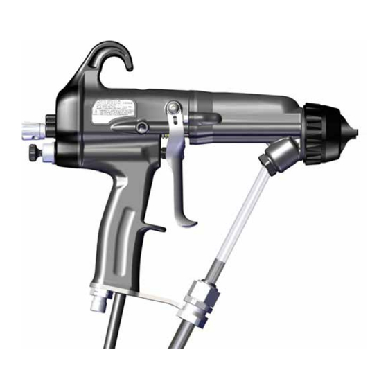
INTRODUCTION Return To Contents SPECIFICATIONS: 81520 RANSFLEX DIRECT CHARGE WATERBASE Environmental/Physical Applicator Length: 273mm (10.75 inches) Weight: (Without Hose) 620 grams (22 oz.) Hose 80558-XX Lengths (Std): 5m, 10m, 15m and 20m Electrical Operating Voltage: 65kV DC (-) maximum Current Output: 120 microamperes maximum Paint Resistance:* Water base paint only... - Page 16 INTRODUCTION Return To Contents Figure 1: RansFlex Water Base Direct Charge Electrostatic Spray Applicator 81520 RANSFLEX WATER BASE DIRECT CHARGE ELECTROSTATIC SPRAY APPLICATOR 81520 Description Description Needle/Electrode Exhaust Air Hose Barrel Waterborne Fluid Hose Handle Voltage On/Off Switch Fan Adjustment Trigger Fluid Adjustment Compensation Valve...
-
Page 17: Typical Installation
INTRODUCTION Return To Contents Figure 2: RansFlex Typical Waterborne Installation RANSFLEX WATERBORNE TYPICAL INSTALLATION Description Description RansFlex 81520 Fluid Regulator Ball Valve Air Hose (80558-XX) Air Regulator with Pressure Gauge Air Hose Ground Wire Air / Water Separator Isolated Waterborne Hose Main Air Supply Line Voltage Isolation / Protection Fluid Supply (Grounded) -
Page 18: Installation
(RH) of the air should be 5%. ordinances as well as NFPA, OSHA, and all related country safety codes prior to installing, 2. Ransburg recommends that a fluid filter be installed operating, and/or servicing this equipment. at the output of the fluid supply (pressure pot, pump, circulating system, etc.). -
Page 19: Waterborne Isolation System Installation Guidelines
INSTALLATION Return To Contents • Air regulations for pots or pumps should be mounted 2. All objects inside spray area must be grounded - remotely outside the fence or cage area to facilitate reference EN 50 176 and/or NFPA-33. Resistance changes in pressure without shutting the system to earth ground must be less than 1 meg Ohm. - Page 20 INSTALLATION Return To Contents 3. Connect air. OR... 4. Trigger applicator with fluid off. Look for leaks in any connections. 5. Activate fluid, check for leaks with solvent flush if required. AH-17-04-R0.0 (11/2017) 20 / 59 www.carlisleft.com...
-
Page 21: Operation
OPERATION Return To Contents OPERATION APPLICATOR OPERATION W A R N I N G 1. Set fluid pressure using flow regulator, insure † The bucket or area sprayed into must be voltage is discharged from system. grounded to true earth ground. 6.9 bar (100psig) Max 1 - Fluid Supply 2 - Flow Regulator... - Page 22 OPERATION Return To Contents Adjust air pressure. Position air cap to achieve pattern direction. 8. Actuate applicator (with voltage off) to spray test pattern. 9. As a guide, the tables below show a pressure at the wall to give 2.7 bar (40 psig) dynamic at the handle of the applicator with different hose lengths.
-
Page 23: Flushing / Color Change Procedure
OPERATION Return To Contents W A R N I N G † The solvent supply must be interlocked with the applicator supply air. 2. Disconnect air to applicator. 15. Adjust compensation valve with small driver. NOTE † The compensation valve adjustment is used to adjust fan and atomization pressure at the OR... -
Page 24: Fluid Nozzle / Air Cap
The following charts show the nozzles and air caps available for the RansFlex. CAUTION † Nozzles from previous Ransburg design are not compatable with the Ransflex design. Use of these nozzles could cause equipment Air cap part number malfunction and possible damage. - Page 25 OPERATION Return To Contents V-65 AIR CAP 80265-00 Static Pressure at Wall Dynamic Pressure at Wall 80558-XX Length psig psig 20 m 15 m 10 m To identify the nozzle, each is engraved with the air cap it must be paired up with. NOZZLE SELECTION 80265-00 / 80264-XX For Use With Air Cap P/N Color...
- Page 26 OPERATION Return To Contents 80231-00 / 80230-XX C SERIES Nozzle Part Number For Use With Air Cap P/N Nozzle Opening Color 80230-12 80231-00 1.2 mm 80230-14 80231-00 Grey 1.4 mm 80230-18 80231-00 Green 1.8 mm 80240-00 / 80239-XX T SERIES Nozzle Part Number For Use With Air Cap P/N Nozzle Opening...
-
Page 27: Air Cap / Nozzle Performance
OPERATION Return To Contents AIR CAP / NOZZLE PERFORMANCE V-65 - 80265-00 Orfice ID Pattern Length Pattern Width *Fluid Delivery Nozzle Spray Type Pressure Reducer (mm/in) (mm/in) (mm/in) (ml/min) 80264-12 1.2/.047 Air Spray 355/14.0 76/3.0 79809-00 (Yellow) 80264-14 1.4/.055 Air Spray 343/13.5 76/3.0 79809-00 (Yellow) -
Page 28: Maintenance
(i.e. high flash Naphtha). If there are any questions as to what solvents are best for † DO NOT operate a faulty applicator! cleaning , contact your local Ransburg distributor and/ or your paint supplier. † When using cleaning solvent, standard health and safety precautions should apply. -
Page 29: Routine Schedule
MAINTENANCE Return To Contents CAUTION CAUTION † Nozzles from previous Ransburg design † NEVER remove the fluid nozzle assembly are not compatable with the Ransflex design. while paint is in the applicator or paint may enter Use of these nozzles could cause equipment into the air passages. - Page 30 MAINTENANCE Return To Contents NOTE † Standard electrode is "snap back" spray wire electrode. • Straighten the applicator electrode if necessary. • Clean the fluid filter, if used. Bi-Yearly • Check air hose resistance. If resistance is greater than 0.5 MegOhm the hose should be replaced. W A R N I N G †...
- Page 31 MAINTENANCE Return To Contents 2. O-ring in barrel, replace as required. 2. Clean and replace as necessary. 3. Install in reverse order. 3. Install fluid nozzle using 80353-00 wrench. Tighten till nozzle seats on O-ring and then 1/8 additional turn. Fluid Nozzle Removal W A R N I N G †...
- Page 32 MAINTENANCE Return To Contents 2. Remove fluid tube. 2. Carefully disconnect harness by pulling connector on both sides by hand and rocking it side to side to remove. 3. Pull barrel away. 3. Replace cascade as necessary. 4. Apply LSCH 0009 grease to end of cascade. Remove/Replace Cascade 1.
- Page 33 MAINTENANCE Return To Contents 5. Remove all parts, clean with non-polar solvent. Packing Removal/Replace Inspect for any discolored areas. Replace parts as required. 1. Remove barrel from handle. 2. Use 80353 wrench to remove nut. 6. Prior to installation apply dielectric grease inside packing tube, completely full.
- Page 34 MAINTENANCE Return To Contents Re-Install Needle Shaft Into Barrel 10. Install Bellville washers in sequence shown. 1. Install needle shaft into barrel with die-electric grease. 11. Install rear nut. Install jam nuts finger tight. 2. Tighten packing using wrench. Pull back and forth on the needle shaft till a slight amount of drag is felt.
- Page 35 MAINTENANCE Return To Contents Re-Install Barrel Rear Cover/Motor Module Repair 1. Install barrel over cascade. 1. Loosen cover screw with 3mm driver. NOTE † The gasket between the handle and barrel is reu- seable. It should only be replaced if torn or damaged. 2.
- Page 36 MAINTENANCE Return To Contents Motor Removal 4. Remove porting block. 1. Remove light pipe. NOTE † Block must be pulled out with fingers rocking the part side to side while pulling. 2. Remove screw and retainer. NOTE † Only remove fluid valve cartridge if parts are being changed.
- Page 37 MAINTENANCE Return To Contents Re-assembly 4. Install screw and retainer. 1. Install porting block on motor. Align screw heads into porting recess. 2. Align motor slots with 3 tab arms. NOTE † There is only one way to install the motor. NOTE †...
- Page 38 MAINTENANCE Return To Contents 9. Tighten cover screw. 6. Install gasket and re-connect motor connector to handle harness connector. NOTE † This gasket is reuseable. It should only be replaced if torn or damaged. Air Valve Remove/Replace 1. Remove trigger. 2.
- Page 39 MAINTENANCE Return To Contents 2. Remove air fitting. 5. Insert air valve and spring. 6. Tighten packing nut till light drag is felt on the shaft 3. Remove bracket, gasket and hose assembly. while moving it back and forth. 7. Install rear cover assembly. 8.
- Page 40 MAINTENANCE Return To Contents 5. Re-install hose components. 6. Install gasket and bracket. NOTE † This gasket is reuseable. It should only be replaced if torn or damaged. Hose Cut Dimensions If the water base hose is serviced for any reason, the cut dimensions are shown below.
- Page 41 MAINTENANCE Return To Contents Gun Wrench Functions 3. Air fiting. 80353-00 1. Adjust packings. 4. Remove rear cartridge. 2. Remove nozzles For V Series For C & T Series AH-17-04-R0.0 (11/2017) 41 / 59 www.carlisleft.com...
-
Page 42: Troubleshooting Guide
MAINTENANCE Return To Contents TROUBLESHOOTING GUIDE General Problem Possible Cause Solution ELECTRICAL On-Off lever in wrong position Ensure the On/Off lever is in the On position. No kV Low pressure Ensure 2.8 bar (40 psig) at the applicator handle with applicator triggered. No ground connection Ensure the air hose is properly grounded to the earth ground. -
Page 43: Parts Identification
PARTS IDENTIFICATION Return To Contents PARTS IDENTIFICATION RANSFLEX RFXw - DIRECT CHARGE WATER BASE 81520 - ABC0EF Base Optional Model No. Designations * NOTE: All nozzles available in kits of 3. ATOMIZATION - TABLE OF “A” DASHES “A” Description “1” “2”... - Page 44 PARTS IDENTIFICATION Return To Contents FLUID CONTROL - TABLE OF “B” DASHES “4” “B” Dash No. “B” Description ADJUSTABLE FLUID 80775-00 NON-ADJUSTABLE FLUID 80775-01 TRIGGER - TABLE OF “C” DASHES “5” “C” Dash No. “C” Description 2 FINGER TRIGGER 80211-00 4 FINGER TRIGGER 80386-00 2 FINGER SMALL PROFILE...
- Page 45 PARTS IDENTIFICATION Return To Contents RETAINING RING 80377-00 Qty. Item No. Part No. Description 80377-00 NUT, RETAINING & O-RING ASSEMBLY (CONTAINS ALL PARTS) LSOR0005-17 O-RING, ENCAPSULATED AH-17-04-R0.0 (11/2017) 45 / 59 www.carlisleft.com...
-
Page 46: Items For Rfxw (65Kv) Unit
PARTS IDENTIFICATION Return To Contents RFXw 65kV BARREL Qty. Item No. Part No. Description 80489-00 ASSEMBLY, BARREL & O-RING 80263-65 ASSEMBLY, NEEDLE SHAFT 80242-00 NUT, REAR JAM 80243-00 NUT, FRONT JAM 80258-00 SPRING, FLUID RETURN 80250-65 ASSEMBLY, CASCADE RFX (65 kV) RFXw 65kV BARREL AND O-RING P/N 80489-00 Qty. - Page 47 PARTS IDENTIFICATION Return To Contents RFXw 65kV NEEDLE SHAFT ASSEMBLY 80263-65 Description Qty. Item No. Part No. 70430-01 ASSEMBLY ELECTRODE, HIGH WEAR 80677-00 ADAPTER, MALE 14323-00 SEAL, CHEVRON, 3/8 DIA. 14323-00-K4 SEAL, CHEVRON (KIT OF 4) 18821-00 ADAPTER-FEMALE-CHEVRON 80257-65 TUBE, PACKING 80225-65 NEEDLE SHAFT ASSEMBLY 79001-06...
-
Page 48: Handle Components For All Models
PARTS IDENTIFICATION Return To Contents HANDLE COMPONENTS FOR ALL MODELS HANDLE COMPONENTS - PARTS LIST Item No. Description Qty. Part No. 80775-00 INCLUDES HANDLE (80870-00) AND REAR COVER WITH MOTOR (80378-00) ASSEMBLY (ADJUSTABLE FLUID CONTROL) 80775-01 INCLUDES HANDLE (80870-00) AND REAR COVER WITH MOTOR (80378-00) ASSEMBLY (NON-ADJUSTABLE FLUID CONTROL) 80745-00 GASKET, BARREL... - Page 49 PARTS IDENTIFICATION Return To Contents HANDLE WITH REAR COVER WITH MOTOR 80775-00/01 Item No. Part No. Description Qty. 80870-00 ASSEMBLY, HANDLE 80244-00 ASSEMBLY, VALVE, AIR 80533-00 SPRING, AIR VALVE 80262-00 ASSEMBLY, VALVE, ADJUSTABLE FLUID CONTROL 80262-01 ASSEMBLY, VALVE, NON-ADJUSTABLE FLUID CONTROL 80273-00 ASSEMBLY, VALVE FAN AIR 80378-00...
- Page 50 PARTS IDENTIFICATION Return To Contents HANDLE ASSEMBLY 80870-00 Description Qty. Item No. Part No. 80870-00 ASSEMBLY, HANDLE INCLUDES ALL PARTS BELOW, MOTOR CONTROL BOARD AND HARNESSES 80274-00 SCREW, BARREL-HANDLE 80229-00 NUT, RETAINING, AIR VALVE 10051-05 CUP SEAL, SPRING LOADED REAR CARTRIDGE ASSEMBLY 80262-00 (ADJUSTABLE FLUID CONTROL) Description Qty.
- Page 51 PARTS IDENTIFICATION Return To Contents REAR CARTRIDGE ASSEMBLY 80262-01 (NON-ADJUSTABLE FLUID CONTROL) Item No. Part No. Description Qty. 80262-01 ASSEMBLY, FLUID CARTRIDGE (NON-ADJUSTABLE) 79001-08 O-RING, SOLVENT PROOF 80273-00 FAN AIR CARTRIDGE Qty. Item No. Part No. Description 80273-00 ASS’Y., FAN VALVE (INCLUDES ALL PARTS BELOW) 79001-16 O-RING, SOLVENT PROOF AH-17-04-R0.0 (11/2017)
- Page 52 PARTS IDENTIFICATION Return To Contents 80378-00 REAR COVER WITH MOTOR ASSEMBLY Description Qty. Item No. Part No. 80378-00 COVER, REAR ASSEMBLY (INCLUDES ALL PARTS BELOW) 80213-00 PIPE, LIGHT 80255-00 ASSEMBLY, MOTOR 79775-00 BLOCK, PORTING 7554-61 O-RING, SOLVENT RESISTANT 80275-00 SCREW 80219-00 BRACKET, LOCKING AH-17-04-R0.0 (11/2017)
- Page 53 PARTS IDENTIFICATION Return To Contents 80255-00 MOTOR ASSEMBLY Qty. Item No. Part No. Description 80255-00 ASSEMBLY, MOTOR (INCLUDES ALL PARTS BELOW) 80217-00 COVER SUPPORT, MOTOR 79796-00 SCREW, MOTOR AH-17-04-R0.0 (11/2017) 53 / 59 www.carlisleft.com...
- Page 54 PARTS IDENTIFICATION Return To Contents 80254-00 REAR COVER ASSEMBLY Qty. Item No. Part No. Description 80254-00 COVER, REAR (CONTAINS PARTS BELOW) 80274-00 M4 X .7 SHCS AH-17-04-R0.0 (11/2017) 54 / 59 www.carlisleft.com...
- Page 55 PARTS IDENTIFICATION Return To Contents WATER BASE HOSE ASSEMBLIES 80500-XX, 80501-XX Qty. Item No. Part No. Description 80498-10 3/16” ID HOSE 80498-15 3/16” ID HOSE 80499-10 1/4” ID HOSE 80499-15 1/4” ID HOSE 10553-05 NUT, SPECIAL 3587-02 NUT, NYLO-SEAL, TUBE FITTING 72310-00 BULKHEAD CONNECTOR ASSEMBLY 72315-00...
-
Page 56: Accessories
PARTS IDENTIFICATION Return To Contents 79862-02 3mm Hex Driver LSCH 0009 Grease 80353-00 Gun Wrench 80395-00 ACCESSORIES INCLUDED WITH RFXw Part No. Description 27141-081 Wrap, Spiral 59972-00 Pack of 4 LSCH0009 Grease 76102-00 Applicator Mounting Bracket 76652-01 HV Probe 76652-02 Spayability and SCI Paint Test Meter Paint Resistivity, Sprayability 76652-03... -
Page 57: Spare Parts Kits
PARTS IDENTIFICATION Return To Contents SPARE PARTS KITS Description Part No. 79001-07-K3 Fluid inlet o-ring of barrels 80264-XX-K3 V Series nozzles in kits of 3 (XX = 12, 14 or 18) 80464-XX-K3 V Series high wear nozzles in kits of 3 (XX = 14, 18) 80230-XX-K3 C Series nozzles in kits of 3 (XX = 12, 14 or 18) 80239-XX-K3... -
Page 58: Recommended Spare Parts
PARTS IDENTIFICATION Return To Contents RECOMMENDED SPARE PARTS RANSFLEX RECOMMENDED SPARE PARTS (Quantities Per Applicator) Part # Description 80264-XX Nozzle, Fluid V Series (See page 42) 80264-XX-K3 Nozzle, Fluid V Series (See page 42) (Kit of 3) 80230-XX Nozzle, Fluid C Series (See page 42) 80230-XX-K3 Nozzle, Fluid C Series (See page 42) (Kit of 3) 80239-XX... - Page 59 ©2017 Carlisle Fluid Technologies, Inc. All rights reserved. Ransburg is part of Carlisle Fluid Technologies, a global leader in innovative finishing technologies. For technical assistance or to locate an authorized distributor, contact one of our international sales and customer support locations.
Need help?
Do you have a question about the RANSFLEX 81520 RFXw and is the answer not in the manual?
Questions and answers