Table of Contents
Advertisement
Quick Links
VECT
VECT
VECT OR AA90 APPLICA
VECT
VECT
MODELS:
MODELS:
MODELS:
MODELS:
MODELS:
OR AA90 APPLICA
OR AA90 APPLICA
OR AA90 APPLICA T T T T T ORS
OR AA90 APPLICA
79580 VECTOR CASCADE
79580 VECTOR CASCADE
79580 VECTOR CASCADE
79580 VECTOR CASCADE
79580 VECTOR CASCADE
79581 VECTOR CLASSIC
79581 VECTOR CLASSIC
79581 VECTOR CLASSIC
79581 VECTOR CLASSIC
79581 VECTOR CLASSIC
IMPORT T T T T ANT
IMPOR
IMPOR
IMPOR
IMPOR
carefully read SAFETY PRECAUTIONS,
carefully read SAFETY PRECAUTIONS,
carefully read SAFETY PRECAUTIONS,
carefully read SAFETY PRECAUTIONS,
carefully read SAFETY PRECAUTIONS,
starting on page 1, and all instructions in this
starting on page 1, and all instructions in this
starting on page 1, and all instructions in this
starting on page 1, and all instructions in this
starting on page 1, and all instructions in this
manual. Keep this Service Manual for future
manual. Keep this Service Manual for future
manual. Keep this Service Manual for future
manual. Keep this Service Manual for future
manual. Keep this Service Manual for future
reference.
reference.
reference.
reference.
reference.
ANT: Before using this equipment,
ANT
ANT
ANT
: Before using this equipment,
: Before using this equipment,
: Before using this equipment,
: Before using this equipment,
Service Manual Price:
Service Manual Price:
Service Manual Price:
Service Manual Price:
Service Manual Price:
SERVICE MANUAL
AH-07-01.8
AH-07-01.8
AH-07-01.8
AH-07-01.8
AH-07-01.8
(Replaces AH-07-01.7)
June 2010
ORS
ORS
ORS
ORS
40.00 (Euro)
40.00 (Euro)
€40.00 (Euro)
40.00 (Euro)
40.00 (Euro)
$50.00 (U.S.)
$50.00 (U.S.)
$50.00 (U.S.)
$50.00 (U.S.)
$50.00 (U.S.)
Advertisement
Table of Contents

Subscribe to Our Youtube Channel
Related Manuals for Ransburg Vector AA90 79580


Summary of Contents for Ransburg Vector AA90 79580
- Page 1 SERVICE MANUAL AH-07-01.8 AH-07-01.8 AH-07-01.8 AH-07-01.8 AH-07-01.8 (Replaces AH-07-01.7) June 2010 VECT VECT OR AA90 APPLICA OR AA90 APPLICA OR AA90 APPLICA T T T T T ORS VECT OR AA90 APPLICA VECT VECT OR AA90 APPLICA MODELS: MODELS: 79580 VECTOR CASCADE 79580 VECTOR CASCADE MODELS: MODELS:...
- Page 2 N O T E : N O T E : N O T E : N O T E : N O T E : This manual has been changed from revision AH-07-01.7 AH-07-01.7 AH-07-01.7 AH-07-01.7 AH-07-01.7 to revision AH-07-01.8. AH-07-01.8.
-
Page 3: Table Of Contents
INTRODUCTION: INTRODUCTION: INTRODUCTION: 13-20 13-20 13-20 13-20 13-20 THE ITW RANSBURG ELECTROSTATIC VECTOR AA90 PROCESS........CASCADE - CASCADE - CASCADE - CASCADE - CASCADE - - SPECIFICATIONS SOLVENTBORNE (CASCADE)............- 79513-13X CONTROL UNIT ELECTRICAL SPECIFICATIONS.......... - AA90 CASCADE SOLVENTBORNE ELECTROSTATIC SPRAY APPLICATOR FEATURES - AIR ASSIST.............. - Page 4 Vector AA90 Applicators - Contents CONTENTS (Cont.) CONTENTS (Cont.) CONTENTS (Cont.) CONTENTS (Cont.) CONTENTS (Cont.) PAGE PAGE PAGE PAGE PAGE INSTALLATION (Cont.): INSTALLATION (Cont.): INSTALLATION (Cont.): INSTALLATION (Cont.): INSTALLATION (Cont.): 21-38 21-38 21-38 21-38 21-38 CLASSIC - CLASSIC - CLASSIC - CLASSIC - CLASSIC - - INTERLOCKS.........................
- Page 5 Vector AA90 Applicators - Contents CONTENTS (Cont.) CONTENTS (Cont.) CONTENTS (Cont.) CONTENTS (Cont.) CONTENTS (Cont.) P A G E P A G E P A G E P A G E P A G E PARTS IDENTIFICATION: PARTS IDENTIFICATION: PARTS IDENTIFICATION: PARTS IDENTIFICATION: PARTS IDENTIFICATION: 69-80...
-
Page 6: Safety
Safety Section in this manual and and understand all of the technical and safety the ITW Ransburg safety literature therein literature for your ITW Ransburg products. This identified. manual contains information that is important for you to know and understand. This information... -
Page 7: Hazards / Safeguards
Vector AA90 Applicators - Safety H A Z A R D H A Z A R D SAFEGUARDS SAFEGUARDS A R E A A R E A A R E A A R E A A R E A H A Z A R D H A Z A R D H A Z A R D SAFEGUARDS... - Page 8 Vector AA90 Applicators - Safety A R E A A R E A A R E A A R E A A R E A H A Z A R D H A Z A R D H A Z A R D H A Z A R D H A Z A R D SAFEGUARDS...
- Page 9 Vector AA90 Applicators - Safety A R E A A R E A A R E A A R E A A R E A H A Z A R D H A Z A R D H A Z A R D H A Z A R D H A Z A R D SAFEGUARDS...
- Page 10 Warranty will be voided if the High Voltage Multiplier seal is broken. If the High Voltage Multiplier is defective contact your authorized ITW Ransburg representative for exchange or repair. The High Voltage Multiplier and high voltage cable contain significant capacitance that will store charge.
- Page 11 Vector AA90 Applicators - Safety H A Z A R D H A Z A R D SAFEGUARDS SAFEGUARDS A R E A A R E A A R E A A R E A A R E A H A Z A R D H A Z A R D H A Z A R D SAFEGUARDS...
-
Page 12: Atex/Fm
Vector AA90 Applicators - Atex EUROPEAN EUROPEAN EUROPEAN ATEX DIRECTIVE DIRECTIVE DIRECTIVE 94/9/EC, ANNEX II, 1.0.6 94/9/EC, ANNEX II, 1.0.6 94/9/EC, ANNEX II, 1.0.6 EUROPEAN EUROPEAN DIRECTIVE DIRECTIVE 94/9/EC, ANNEX II, 1.0.6 94/9/EC, ANNEX II, 1.0.6 The following instructions apply to equipment 8. -
Page 13: European Atex Labels
Vector AA90 Applicators - Atex Label 79515 Label 79515 Label 79515 Label 79515 Label 79515 V V V V V ector AA90 79580 and 79581 ector AA90 79580 and 79581 ector AA90 79580 and 79581 ector AA90 79580 and 79581 ector AA90 79580 and 79581 A A A A A TEX Product Marking TEX Product Marking... -
Page 14: Fm Configuration Drawings
"C" DESIGNATIONS "B" DESIGNATIONS "A" DESIGNATIONS "D" DESIGN ATIONS "E" DESIGNATIONS CONFIGURATION DWG. 79952 REV A 9 9 9 9 9 AH-07-01.8... - Page 15 OPTION "A" DESIGNATIONS CABLE LENGTH 0 FOR NO CABLE 1 FOR 10 METER CABLE-PART NUMBER: 79338-10 2 FOR 15 METER CABLE-PART NUMBER: 79338-15 3 FOR 20 METER CABLE-PART NUMBER: 79338-10 (2) 4 FOR 25 METER CABLE-PART NUMBER: 79338-10 (1) & 793 38-15 (1) 5 FOR 30 METER CABLE-PART NUMBER: 79338-15 (2) OPTION "B"...
- Page 16 "C" DESIGNATIONS "B" DESIGNATIONS "A" DESIGNATIONS "E" DESIGNATIONS "D" DESIGNATIONS CONFIGURATION DWG. 79953 REV A AH-07-01.8...
- Page 17 OPTION "A" DESIGNATIONS CABLE LENGTH 0 FOR NO CABLE 1 FOR 10 METER CABLE-PART NUMBER: 79519-10 2 FOR 15 METER CABLE-PART NUMBER: 79519-15 3 FOR 20 METER CABLE-PART NUMBER: 79519-20 4 FOR 25 METER CABLE-PART NUMBER: 79519-25 5 FOR 30 METER CABLE-PART NUMBER: 79519-30 OPTION "B"...
-
Page 18: Introduction
Vector AA90 Applicators - Introduction INTRODUCTION INTRODUCTION INTRODUCTION INTRODUCTION INTRODUCTION THE ITW RANSBURG THE ITW RANSBURG THE ITW RANSBURG THE ITW RANSBURG THE ITW RANSBURG As the applicator electrode approaches ground, the power supply and applicator circuitry cause ELECTROST ELECTROST... - Page 19 Vector AA90 Applicators - Introduction N O T E S N O T E S N O T E S N O T E S N O T E S AH-07-01.8...
-
Page 20: Cascade
Vector AA90 Applicators - Introduction SPECIFICA SPECIFICA TIONS TIONS 79513-13X CONTROL 79513-13X CONTROL SPECIFICA SPECIFICATIONS SPECIFICA TIONS TIONS 79513-13X CONTROL 79513-13X CONTROL 79513-13X CONTROL VENTBORNE VENTBORNE UNIT ELECTRICAL UNIT ELECTRICAL SOLVENTBORNE VENTBORNE VENTBORNE UNIT ELECTRICAL UNIT ELECTRICAL UNIT ELECTRICAL ( ( ( ( ( CASCADE) CASCADE) CASCADE) CASCADE) -
Page 21: Aa90 Cascade Solventborne Electrostatic Spray Applicator Features - Air Assist
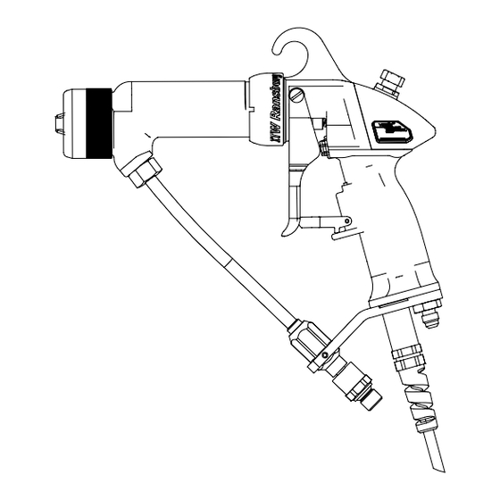
Vector AA90 Applicators - Introduction Figure 1: AA90 Cascade Solventborne Electrostatic Spray Applicator Features - Air Assist Figure 1: AA90 Cascade Solventborne Electrostatic Spray Applicator Features - Air Assist Figure 1: AA90 Cascade Solventborne Electrostatic Spray Applicator Features - Air Assist Figure 1: AA90 Cascade Solventborne Electrostatic Spray Applicator Features - Air Assist Figure 1: AA90 Cascade Solventborne Electrostatic Spray Applicator Features - Air Assist AA90 CASCADE SOL... -
Page 22: 79513-13X Cascade Control Unit Features
Vector AA90 Applicatorss - Introduction Figure 2: Figure 2: Figure 2: Figure 2: Figure 2: 79513-13X Cascade Control Unit Features 79513-13X Cascade Control Unit Features 79513-13X Cascade Control Unit Features 79513-13X Cascade Control Unit Features 79513-13X Cascade Control Unit Features 79513-13X CASCADE CONTROL 79513-13X CASCADE CONTROL 79513-13X CASCADE CONTROL... -
Page 23: Specifications Solventborne (Classic)
Vector AA90 Applicators - Introduction SPECIFICA SPECIFICA TIONS TIONS 79344-14X 9050 POWER 79344-14X 9050 POWER SPECIFICA SPECIFICATIONS SPECIFICA TIONS TIONS 79344-14X 9050 POWER 79344-14X 9050 POWER 79344-14X 9050 POWER VENTBORNE VENTBORNE SUPPL SUPPLY Y Y Y Y ELECTRICAL SUPPL ELECTRICAL ELECTRICAL SOLVENTBORNE VENTBORNE... -
Page 24: Aa90 Classic Solventborne Electrostatic Spray Applicator Features - Air Assist
Vector AA90 Applicators - Introduction Figure 3: Figure 3: Figure 3: AA90 Classic Solventborne Electrostatic Spray Applicator Features - Air Assist AA90 Classic Solventborne Electrostatic Spray Applicator Features - Air Assist AA90 Classic Solventborne Electrostatic Spray Applicator Features - Air Assist Figure 3: Figure 3: AA90 Classic Solventborne Electrostatic Spray Applicator Features - Air Assist... -
Page 25: 79344-14X 9050 Power Supply Features
Vector AA90 Applicators - Introduction Figure 4: Figure 4: 79344-14X 9050 Power Supply Features 79344-14X 9050 Power Supply Features Figure 4: Figure 4: Figure 4: 79344-14X 9050 Power Supply Features 79344-14X 9050 Power Supply Features 79344-14X 9050 Power Supply Features 79344-14X 9050 POWER SUPPL 79344-14X 9050 POWER SUPPLY Y Y Y Y FEA 79344-14X 9050 POWER SUPPL... -
Page 26: Installation
TION TION TION INST INST ALLA TION and should be directed by an ITW Ransburg representative. Connect the low voltage cable to the control unit low voltage socket. Gently hand tighten the cable retaining SAFE INST SAFE INST SAFE INSTALLA... -
Page 27: Typical Aa90 Cascade Applicator Installation Features
Vector AA90 Applicators - Installation R<1 Meg Ohm Figure 5: Figure 5: Figure 5: Figure 5: Figure 5: Typical AA90 Cascade Applicator Installation Features Typical AA90 Cascade Applicator Installation Features Typical AA90 Cascade Applicator Installation Features Typical AA90 Cascade Applicator Installation Features Typical AA90 Cascade Applicator Installation Features TYPICAL TYPICAL... -
Page 28: Mounting The Control Unit
Vector AA90 Applicators - Installation MOUNTING THE MOUNTING THE MOUNTING THE MOUNTING THE MOUNTING THE C A U T I O N C A U T I O N C A U T I O N C A U T I O N C A U T I O N ! ! ! ! ! CONTROL UNIT... -
Page 29: 79527-00 9050 Cascade Enclosures
Vector AA90 Applicators - Installation Figure 6: Figure 6: Figure 6: 79527-00 9050 Cascade Enclosures 79527-00 9050 Cascade Enclosures 79527-00 9050 Cascade Enclosures Figure 6: Figure 6: 79527-00 9050 Cascade Enclosures 79527-00 9050 Cascade Enclosures AH-07-01.8... -
Page 30: Electrical Noise
Vector AA90 Applicators - Installation ELECTRICAL NOISE ELECTRICAL NOISE It is recommended that all AC I/O (interlocks) be ELECTRICAL NOISE ELECTRICAL NOISE ELECTRICAL NOISE run in conduit. If desired and codes permit, cabling may be used for these signals, but for maximum General Information - Classic or General Information - Classic or General Information - Classic or... -
Page 31: I/O Connections (Cascade Units)
Vector AA90 Applicators - Installation I/O CONNECTIONS I/O CONNECTIONS I/O CONNECTIONS I/O CONNECTIONS I/O CONNECTIONS (CASCADE UNITS) (CASCADE UNITS) (CASCADE UNITS) (CASCADE UNITS) (CASCADE UNITS) For maximum noise immunity, I/O wiring should be run in conduit or cables having a foil shield with an overall braided shield. -
Page 32: Ac Input Connections (Cascade Units)
Vector AA90 Applicators - Installation 2. Remove the mounting hardware from the AC AC INPUT AC INPUT AC INPUT AC INPUT AC INPUT inlet receptacle and remove it from the rear of the CONNECTIONS CONNECTIONS CONNECTIONS CONNECTIONS CONNECTIONS control unit. ( ( ( ( ( CASCADE UNITS CASCADE UNITS CASCADE UNITS... -
Page 33: Relay Contact Outputs
Vector AA90 Applicators - Installation W A R N I N G W A R N I N G W A R N I N G N O T E N O T E N O T E W A R N I N G W A R N I N G N O T E N O T E... - Page 34 Vector AA90 Applicators - Installation Figure 10a: Figure 10a: Figure 10a: Figure 10a: Figure 10a: Location of Terminal Blocks Location of Terminal Blocks Location of Terminal Blocks Location of Terminal Blocks Location of Terminal Blocks TB1 and TB2 TB1 and TB2 TB1 and TB2 TB1 and TB2 TB1 and TB2...
-
Page 35: Low Voltage Cable
Vector AA90 Applicators - Installation LOW VOL LOW VOL LOW VOLT T T T T AGE CABLE AGE CABLE AGE CABLE LOW VOL LOW VOL AGE CABLE AGE CABLE W A R N I N G W A R N I N G W A R N I N G W A R N I N G W A R N I N G... -
Page 36: Typical Aa90 Classic Applicator Installation Features
Vector AA90 Applicators - Installation R<1 Meg Ohm Figure 12: Figure 12: Figure 12: Figure 12: Figure 12: Typical AA90 Classic Applicator Installation Features Typical AA90 Classic Applicator Installation Features Typical AA90 Classic Applicator Installation Features Typical AA90 Classic Applicator Installation Features Typical AA90 Classic Applicator Installation Features TYPICAL TYPICAL... -
Page 37: Classic Power Supply Installation
Vector AA90 Applicators - Installation CLASSIC POWER CLASSIC POWER I/O CONNECTIONS I/O CONNECTIONS I/O CONNECTIONS CLASSIC POWER CLASSIC POWER CLASSIC POWER I/O CONNECTIONS I/O CONNECTIONS SUPPL SUPPL SUPPLY Y Y Y Y INST INST INST INSTALLA ALLA ALLATION ALLA TION TION TION SUPPL... -
Page 38: Ac Input Connections (Classic Units)
Vector AA90 Applicators - Installation N O T E N O T E N O T E N O T E N O T E Due to variations in source connec- > tions, European units are shipped without an AC line cord. When selecting a line cord for these units, select one that has the ap- propriate source connector at the plug end, and an IEC-60320 C13 connector at the... -
Page 39: Input Voltage Selection
Vector AA90 Applicators - Installation 4. Install the AC input wiring (0.8mm (18 AWG) minimum) through the Conduit Adapter Plate using conduit and wire to TB1 as follows: Hot/Line to TB1-L1 Neutral/Common to TB1-N Ground to TB1-EARTH GROUND Safety Ground Safety Ground Safety Ground Safety Ground... -
Page 40: Interlocks
Consult your authorized ITW Ransburg representative for information on interlocking the high voltage OFF signal with the solvent flush signal. As outlined in NFPA-33 and OSHA, the AC power line must be series interlocked with both the exhaust fan and conveyor. -
Page 41: High Voltage Cable
Vector AA90 Applicators - Installation HIGH VOL HIGH VOLT T T T T AGE CABLE HIGH VOL AGE CABLE AGE CABLE HIGH VOL HIGH VOL AGE CABLE AGE CABLE W A R N I N G W A R N I N G W A R N I N G W A R N I N G W A R N I N G... -
Page 42: Relay Contact Outputs
MAXIMUM CONT MAXIMUM CONTACT ACT RA RATINGS TINGS TINGS Description Description ITW Ransburg supplies a standard 2m whip hose Description Description Description with all applicator assemblies. Connect air hose of Max. Switching Capacity 62.5VA proper size and length based on application. - Page 43 Vector AA90 Applicators - Installation N O T E S N O T E S N O T E S N O T E S N O T E S AH-07-01.8...
-
Page 44: Operation
N O T E N O T E N O T E shooting Guide" or contact your authorized ITW Ransburg representative. The degree of atomization is depen- > dent on the viscosity of the paint formula- • Ground MUST be maintained during the addition... -
Page 45: Preparation
> fluid nozzle precision is paramount to proper at ground potential. The applicator opera- function. ITW Ransburg makes every effort to tor is also grounded, therefore, the opera- assure that all production of this part will meet the tor has as much attraction for the electro- critical design standards necessary for all static paint as the object. -
Page 46: 79634-Xx Pre-Orifice Seal Sizes
Vector AA90 Applicators - Operation Table II shows the available pre-orifice sizes. The pre-orifice selected should be sized approximately TABLE I TABLE I TABLE I TABLE I TABLE I .025mm (.001-inch) larger than the tip size opening. NOZZLE SELECTION GUIDE NOZZLE SELECTION GUIDE NOZZLE SELECTION GUIDE NOZZLE SELECTION GUIDE... -
Page 47: Kv Test Jumper
Vector AA90 Applicators - Operation KV TEST JUMPER KV TEST JUMPER Cable Fault (CF) Cable Fault (CF) Cable Fault (CF) KV TEST JUMPER KV TEST JUMPER KV TEST JUMPER Cable Fault (CF) Cable Fault (CF) (Classic Units) (Classic Units) (Classic Units) (Classic Units) (Classic Units) This fault will occur if high voltage is active and the... - Page 48 Vector AA90 Applicators - Operation Safety Fault (SF) Safety Fault (SF) Safety Fault (SF) Overload Fault (OL) Overload Fault (OL) Overload Fault (OL) Safety Fault (SF) Safety Fault (SF) Overload Fault (OL) Overload Fault (OL) (Cascade Units) (Cascade Units) (Cascade Units) (Cascade Units) (Cascade Units) (Cascade Units)
- Page 49 Feedback Fault (FF) Feedback Fault (FF) Feedback Fault (FF) Feedback Fault (FF) Feedback Fault (FF) (Cascade Units) (Cascade Units) (Cascade Units) (Cascade Units) (Cascade Units) This fault will occur if the microprocessor detects a loss of the current feedback signal. If this occurs, reset the fault from the applicator or control unit.
-
Page 50: Powering Up Control Unit (Cascade Units)
POWERING UP POWERING UP POWERING UP POWERING UP POWERING UP CONTROL UNIT CONTROL UNIT CONTROL UNIT CONTROL UNIT CONTROL UNIT ( ( ( ( ( CASCADE UNITS CASCADE UNITS CASCADE UNITS CASCADE UNITS) ) ) ) ) CASCADE UNITS When the AC power is turned on, the unit will display the PC board applicator type number on the kV setpoint display and the software revision level in the μA display for 2-3 seconds. -
Page 51: Setpoint Voltage
Vector AA90 Applicators - Operation SETPOINT SETPOINT SETPOINT SETPOINT SETPOINT VOL VOLT T T T T AGE When a kV setpoint button is pressed, the light above the button will light and the kV display will show the present voltage for that setpoint. This The Vector applicator system has three voltage indicates the unit is set to spray at that setpoint. -
Page 52: Lockouts
Vector AA90 Applicators - Operation kV to the applicator can be turned off by pressing the applicator kV button in for 2-3 seconds. This can be done whether the applicator is triggered or not and is useful if the kV needs to be turned off for spraying into recessed areas. - Page 53 Vector AA90 Applicators - Operation Applicator Switch Lockout Applicator Switch Lockout Applicator Switch Lockout 3. Close the control unit and turn the AC power Applicator Switch Lockout Applicator Switch Lockout back on. An overload fault will now occur if the The applicator switch may be de-activated for microamp display comes within 10 microamps of applications that require the operator to not be able...
-
Page 54: Basic Operation (Cascade Units)
Vector AA90 Applicators - Operation BASIC OPERA BASIC OPERA TION TION BASIC OPERA BASIC OPERA BASIC OPERATION TION TION (CASCADE UNITS) (CASCADE UNITS) (CASCADE UNITS) (CASCADE UNITS) (CASCADE UNITS) T T T T T riggering riggering riggering riggering riggering High voltage is actuated by pulling the trigger to start the flow of atomizing and fan control air through the applicator. -
Page 55: Start-Up (Classic Units)
Vector AA90 Applicators - Operation To reset this register, press the reset button while the hours are displayed. Pressing the preset 2 and reset buttons at the same time will show the number of hours on the non-re-settable register. Local/Remote Local/Remote Local/Remote Local/Remote... -
Page 56: Setting And Adjusting Output Voltage
Vector AA90 Applicators - Operation SETTING AND SETTING AND BASIC OPERA BASIC OPERA TIONS TIONS SETTING AND SETTING AND SETTING AND BASIC OPERA BASIC OPERATIONS BASIC OPERA TIONS TIONS ADJUSTING OUTPUT ADJUSTING OUTPUT ADJUSTING OUTPUT ADJUSTING OUTPUT ADJUSTING OUTPUT (CLASSIC UNITS) (CLASSIC UNITS) (CLASSIC UNITS) (CLASSIC UNITS) - Page 57 Vector AA90 Applicators - Operation Measuring "High V Measuring "High V Measuring "High Voltage On" oltage On" oltage On" oltage On" Measuring "High V Measuring "High V oltage On" Local/Remote Mode Button Local/Remote Mode Button Local/Remote Mode Button Local/Remote Mode Button Local/Remote Mode Button T T T T T ime The 9050 Power Supply product line is designed...
-
Page 58: To Remove The Applicator From The Work Site
Vector AA90 Applicators - Operation TO REMOVE THE TO REMOVE THE TO REMOVE THE TO REMOVE THE TO REMOVE THE APPLICA APPLICA APPLICAT T T T T OR FROM THE OR FROM THE OR FROM THE APPLICA APPLICA OR FROM THE OR FROM THE WORK SITE WORK SITE... -
Page 59: Applicator Repair
Vector AA90 Applicators - Operation APPLICA APPLICA APPLICAT T T T T OR REP OR REP OR REP EQUIPMENT REQUIRED EQUIPMENT REQUIRED APPLICA APPLICA OR REP OR REPAIR EQUIPMENT REQUIRED EQUIPMENT REQUIRED EQUIPMENT REQUIRED • Special Multi-Purpose Applicator All repairs should be made on a clean, flat surface. Wrench 19749-00 If a vise is used to hold parts during service or repair, DO NOT clamp onto plastic parts and... -
Page 60: Maintenance
ROUTINE SCHEDULE ROUTINE SCHEDULE ROUTINE SCHEDULE ROUTINE SCHEDULE needs to be removed. ITW Ransburg recommends that all exterior cleaning be done with non-polar solvents to prevent a conductive residue on critical Follow these maintenance steps to extend the components. We also understand that some of... - Page 61 Vector AA90 Applicators - Maintenance Daily (or at start of each shift) Daily (or at start of each shift) Daily (or at start of each shift) 5. Holding the metal portion of the high voltage Daily (or at start of each shift) Daily (or at start of each shift) probe in your hand, trigger the applicator so voltage •...
-
Page 62: Flushing Procedures
Vector AA90 Applicators - Maintenance FLUSHING FLUSHING FLUSHING FLUSHING FLUSHING C A U T I O N C A U T I O N C A U T I O N C A U T I O N C A U T I O N ! ! ! ! ! PROCEDURES PROCEDURES... - Page 63 Vector AA90 Applicators - Maintenance W A R N I N G W A R N I N G W A R N I N G C A U T I O N C A U T I O N C A U T I O N W A R N I N G W A R N I N G...
- Page 64 Vector AA90 Applicators - Maintenance Spray T Spray T Spray Tip Removal/Carbide ip Removal/Carbide ip Removal/Carbide ip Removal/Carbide Spray T Spray T ip Removal/Carbide Removal Removal Removal Removal Removal 1. Remove the retaining nut completely by hand. 2. Remove the air cap from applicator using the tool provided.
- Page 65 Vector AA90 Applicators - Maintenance Figure 44b: Figure 44b: Figure 44b: Barrel Disassembly Barrel Disassembly Barrel Disassembly Figure 44b: Figure 44b: Barrel Disassembly Barrel Disassembly 3. Pull needle shaft assembly straight out. Needle Shaft Packing Needle Shaft Packing Needle Shaft Packing Needle Shaft Packing Needle Shaft Packing Replacement...
- Page 66 Vector AA90 Applicators - Maintenance 2. Using two 74133 tools, remove carbide ball and Needle Shaft Pack Reassembly Needle Shaft Pack Reassembly Needle Shaft Pack Reassembly Needle Shaft Pack Reassembly Needle Shaft Pack Reassembly jam nut. Remove packing components. 1. Install pusher seal, rear u-cup, rear spreader seal, front u-cup seal, front spreader seal as shown.
- Page 67 Vector AA90 Applicators - Maintenance Rebuild Barrel Rebuild Barrel Rebuild Barrel Rebuild Barrel Rebuild Barrel 1. Install tip and seals into barrel. Figure 48c: Figure 48c: Figure 48c: Figure 48c: Figure 48c: Rebuilding Barrel Rebuilding Barrel Rebuilding Barrel Rebuilding Barrel Rebuilding Barrel Figure 48a: Figure 48a:...
- Page 68 Vector AA90 Applicators - Maintenance Figure 50b: Figure 50b: Figure 50b: Figure 50b: Figure 50b: Handle Disassembly Handle Disassembly Handle Disassembly Handle Disassembly Handle Disassembly 4. Remove trigger lock assembly. Figure 49b: Figure 49b: Figure 49b: Figure 49b: Figure 49b: Install Barrel on Handle Install Barrel on Handle Install Barrel on Handle...
- Page 69 Vector AA90 Applicators - Maintenance 8. For Cascade Units - remove plug assembly. Figure 50d: Figure 50d: Figure 50d: Figure 50d: Figure 50d: Handle Disassembly Handle Disassembly Handle Disassembly Handle Disassembly Handle Disassembly Figure 50g: Figure 50g: Figure 50g: Handle Disassembly Handle Disassembly Handle Disassembly Figure 50g:...
-
Page 70: Troubleshooting Guide
3. Reduce air pressure to pump. 4. Applicator held too close 4. Hold applicator further back. to target 5. Paint too conductive 5. Consult ITW Ransburg technical assistance. 6. Poor target ground 6. Check ground integrity from target through support to ground. Paint Wraps Back... -
Page 71: (Continued On Next Page)
Vector AA90 Applicators - Maintenance TROUBLESHOOTING GUIDE (Cont.) TROUBLESHOOTING GUIDE (Cont.) TROUBLESHOOTING GUIDE (Cont.) TROUBLESHOOTING GUIDE (Cont.) TROUBLESHOOTING GUIDE (Cont.) General Problem General Problem General Problem General Problem General Problem Possible Cause Possible Cause Possible Cause Possible Cause Possible Cause Solution Solution Solution... - Page 72 Vector AA90 Applicators - Maintenance TROUBLESHOOTING GUIDE (Cont.) TROUBLESHOOTING GUIDE (Cont.) TROUBLESHOOTING GUIDE (Cont.) TROUBLESHOOTING GUIDE (Cont.) TROUBLESHOOTING GUIDE (Cont.) General Problem General Problem General Problem General Problem General Problem Possible Cause Possible Cause Possible Cause Possible Cause Possible Cause Solution Solution Solution...
- Page 73 Vector AA90 Applicators - Maintenance N O T E S N O T E S N O T E S N O T E S N O T E S AH-07-01.8...
- Page 74 Vector AA90 Applicators - Parts Identification P P P P P AR AR TS IDENTIFICA TS IDENTIFICA TS IDENTIFICA TION TS IDENTIFICA TION TION TION TS IDENTIFICA TION 79580 VECT 79580 VECT AA90 APPLICA AA90 APPLICA AA90 APPLICAT T T T T OR 79580 VECT 79580 VECTOR 79580 VECT...
- Page 75 Vector AA90 Applicators - Parts Identification P P P P P AR AR TS IDENTIFICA TS IDENTIFICA TS IDENTIFICA TION TS IDENTIFICA TION TION TION TS IDENTIFICA TION 79581 VECT 79581 VECT AA90 APPLICA AA90 APPLICA AA90 APPLICAT T T T T OR 79581 VECT 79581 VECT 79581 VECTOR...
- Page 76 Vector AA90 Applicators - Parts Identification Figure 51: Figure 51: Figure 51: Figure 51: Figure 51: Vector AA90 Cascade Exploded View Vector AA90 Cascade Exploded View Vector AA90 Cascade Exploded View Vector AA90 Cascade Exploded View Vector AA90 Cascade Exploded View AH-07-01.8...
- Page 77 Vector AA90 Applicators - Parts Identification VECT VECT VECTOR AA90 CASCADE - P OR AA90 CASCADE - P OR AA90 CASCADE - P OR AA90 CASCADE - PAR ARTS LIST TS LIST TS LIST (Figure 51) TS LIST (Figure 51) (Figure 51) (Figure 51) VECT...
- Page 78 Vector AA90 Applicators - Parts Identification 9 38 Figure 52: Figure 52: Figure 52: Figure 52: Figure 52: Vector AA90 Classic Exploded View Vector AA90 Classic Exploded View Vector AA90 Classic Exploded View Vector AA90 Classic Exploded View Vector AA90 Classic Exploded View AH-07-01.8...
- Page 79 Vector AA90 Applicators - Parts Identification VECT VECT VECTOR AA90 CLASSIC - P OR AA90 CLASSIC - P OR AA90 CLASSIC - P OR AA90 CLASSIC - PAR ARTS LIST TS LIST TS LIST (Figure 52) TS LIST (Figure 52) (Figure 52) (Figure 52) VECT...
- Page 80 Vector AA90 Applicators - Parts Identification Figure 53: Figure 53: Figure 53: Figure 53: Figure 53: Accessories Accessories Accessories Accessories Accessories ACCESSORIES - P ACCESSORIES - P TS LIST TS LIST (Figure 53) * (Figure 53) * ACCESSORIES - P ACCESSORIES - P ACCESSORIES - PAR ARTS LIST...
- Page 81 Vector AA90 Applicators - Parts Identification 7994-XX FLUID LINE 7994-XX FLUID LINE 7994-XX FLUID LINE 7994-XX FLUID LINE 7994-XX FLUID LINE (Figure 54) (Figure 54) (Figure 54) (Figure 54) (Figure 54) Length Length Length Length Length Part Number Part Number Part Number Part Number Part Number...
- Page 82 Vector AA90 Applicators - Parts Identification Figure 56: Figure 56: Figure 56: Figure 56: Figure 56: Fan Air Valve Components Fan Air Valve Components Fan Air Valve Components Fan Air Valve Components Fan Air Valve Components F F F F F AN AIR V AN AIR V AN AIR V AN AIR VAL...
- Page 83 Vector AA90 Applicators - Parts Identification Figure 57: Figure 57: Figure 57: 79513-13X Control Unit 79513-13X Control Unit 79513-13X Control Unit Figure 57: Figure 57: 79513-13X Control Unit 79513-13X Control Unit 79513-13X CONTROL 79513-13X CONTROL 79513-13X CONTROL UNIT UNIT UNIT UNIT - P - PAR ARTS LIST...
- Page 84 Vector AA90 Applicators - Parts Identification Figure 58: Figure 58: Figure 58: Figure 58: Figure 58: AA90 Classic Power Supply AA90 Classic Power Supply AA90 Classic Power Supply AA90 Classic Power Supply AA90 Classic Power Supply AA90 CLASSIC POWER SUPPL AA90 CLASSIC POWER SUPPL AA90 CLASSIC POWER SUPPLY Y Y Y Y - P AA90 CLASSIC POWER SUPPL...
- Page 85 Vector AA90 Applicators - Parts Identification AA90 APPLICA AA90 APPLICA AA90 APPLICAT T T T T ORS RECOMMENDED SP ORS RECOMMENDED SP ORS RECOMMENDED SP ARE P ARE P AA90 APPLICA AA90 APPLICA ORS RECOMMENDED SP ORS RECOMMENDED SPARE P ARE P ARE PAR ARTS...
- Page 86 EXCLUSIONS: EXCLUSIONS: SPARE PARTS: One hundred and eighty (180) If, in ITW Ransburg's opinion the warranty item in days from date of purchase, except for rebuilt question, or other items damaged by this part was parts (any part number ending in "R") for which the improperly installed, operated or maintained, ITW warranty period is ninety (90) days.
- Page 87 MANUAL MANUAL CHANGE SUMMAR CHANGE SUMMAR CHANGE SUMMAR Y Y Y Y Y MANUAL MANUAL CHANGE SUMMAR MANUAL CHANGE SUMMAR This manual was published to replace Service AH-07-01.7 AH-07-01.7 Manual AH-07-01.7 AH-07-01.7 AH-07-01.7 Vector AA90 Applicators, to make the following changes: 1.
- Page 88 Service Manual Price: Service Manual Price: Service Manual Price: Service Manual Price: Service Manual Price: €40.00 (Euro) 40.00 (Euro) 40.00 (Euro) 40.00 (Euro) 40.00 (Euro) $50.00 (U.S.) $50.00 (U.S.) $50.00 (U.S.) $50.00 (U.S.) $50.00 (U.S.) Manufacturing Manufacturing Manufacturing Manufacturing Manufacturing 1910 North Wayne Street Angola, Indiana 46703-9100 Telephone: 260/665-8800...
Need help?
Do you have a question about the Vector AA90 79580 and is the answer not in the manual?
Questions and answers