Table of Contents
Advertisement
SERVICE MANUAL
AH-15-01.2
JULY - 2015
MODEL: 80345 AND 80365 RX & RFX
IMPORTANT: Before using this equipment, carefully read SAFETY
PRECAUTIONS, starting on page 1, and all instructions in this manual.
Keep this Service Manual for future reference.
®
APPLICATORS
By Ransburg
Service Manual Price:
$50.00 (U.S.)
Advertisement
Table of Contents

Related Manuals for Ransburg RansFlex RX 80345


Summary of Contents for Ransburg RansFlex RX 80345
- Page 1 AH-15-01.2 JULY - 2015 ® APPLICATORS By Ransburg MODEL: 80345 AND 80365 RX & RFX IMPORTANT: Before using this equipment, carefully read SAFETY PRECAUTIONS, starting on page 1, and all instructions in this manual. Keep this Service Manual for future reference.
- Page 2 Ranflex Applicators - REVISIONS NOTE: This manual has been changed from revision AH-15-01 to revision AH-15-01.2. Reasons for this change are noted under “Manual Change Summary” on page 57 of this manual. AH-15-01.2...
-
Page 3: Table Of Contents
Ranflex Applicators - CONTENTS CONTENTS PAGE SAFETY: Safety Precautions ..........................1 Hazards / Safegaurds ........................... 2 ATEX/FM: 6-13 European Atex Directive ........................6 European Atex Labels .......................... 7 FM Configuration Drawings 80345 ....................... 8 FM Configuration Drawings 80365 ....................... 11 INTRODUCTION: 14-18 General Description... -
Page 4: Safety
Before operating, maintaining or servicing any Ransburg W A R N I N G electrostatic coating system, read and understand all of the technical and safety literature for your Ransburg The user MUST read and be familiar with the †... -
Page 5: Hazards / Safegaurds
Ranflex Applicators - SAFETY SAFEGUARDS HAZARD AREA Tells how to avoid the hazard. Tells where hazards Tells what the hazard is. may occur. Spray Area Fire Hazard Fire extinguishing equipment must be present in the spray area and tested periodically. Improper or inadequate operation and maintenance Spray areas must be kept clean to prevent the... - Page 6 Ranflex Applicators - SAFETY SAFEGUARDS HAZARD AREA Tells how to avoid the hazard. Tells where hazards Tells what the hazard is. may occur. Explosion Hazard Spray Area Electrostatic arcing must be prevented. Safe Improper or inadequate oper- sparking distance must be maintained between ation and maintenance proce- the parts being coated and the applicator.
- Page 7 Ranflex Applicators - SAFETY SAFEGUARDS HAZARD AREA Tells how to avoid the hazard. Tells where hazards Tells what the hazard is. may occur. Spray Area / Electrical Discharge High Voltage Parts being sprayed and operators in the spray There is a high voltage device Equipment area must be properly grounded.
- Page 8 Ranflex Applicators - SAFETY SAFEGUARDS HAZARD AREA Tells how to avoid the hazard. Tells where hazards Tells what the hazard is. may occur. Electrical Discharge Electrical Unless specifically approved for use in hazard- Equipment ous locations, the power supply, control cabi- High voltage equipment is net, and all other electrical equipment must be utilized in the process.
-
Page 9: Atex/Fm
Ranflex Applicators - ATEX EUROPEAN ATEX DIRECTIVE 94/9/EC, ANNEX II, 1.0.6 The following instructions apply to equipment covered of the user to take suitable precautions that prevent by certificate number Sira 14ATEX5343: it from being adversely affected, thus ensuring that the type of protection provided by the equipment The equipment may be used with flammable is not compromised. -
Page 10: European Atex Labels
X = Special conditions for safe use apply Special conditions for safe use: The Ransflex 80345/80365 Applicators shall only be used with associated Ransburg 79727-XX Air Hose Assembly. It is the end users responsibility to insure the air hose is properly grounded to true earth ground. -
Page 11: Fm Configuration Drawings 80345
Ranflex Applicators - ATEX RANSFLEX RX - SOLVENT BASE 80345 - ABCDEF Base Optional Model No. Designations (Ordering Information Only) CONFIGURATION DWG. 80368 REV. A Return To Contents AH-15-01.2... - Page 12 Ranflex Applicators - ATEX “T” (Pressure Reducer) “R” (Air Cap) “S” (Fluid Nozzle) ATOMIZATION - TABLE OF “A” DASHES “R” “S” “T” “A” Dash No. “A” Description V SERIES 1.2mm 80265-00 80264-12 79809-00 V SERIES 1.4mm 80265-00 80264-14 79809-00 V SERIES 1.8mm 80265-00 80264-18 79809-00...
- Page 13 Ranflex Applicators - ATEX “W” 80269-45 79879-01 FLUID INLET - TABLE OF “D” DASHES “D” Dash No. “D” Description “W” STD FLUID INLET TUBE 80269-45 COILED FLUID INLET TUBE 79879-01 FLUID HOSE - TABLE OF “E” DASHES “E” Description “X” “E”...
-
Page 14: Fm Configuration Drawings 80365
Ranflex Applicators - ATEX RANSFLEX RFX - SOLVENT BASE 80365 - ABCDEF Base Optional Model No. Designations (Ordering Information Only) CONFIGURATION DWG. 80366 REV. A Return To Contents AH-15-01.2... - Page 15 Ranflex Applicators - ATEX “T” (Pressure Reducer) “R” (Air Cap) “S” (Fluid Nozzle) ATOMIZATION - TABLE OF “A” DASHES “R” “S” “T” “A” Dash No. “A” Description V SERIES 1.2mm 80265-00 80264-12 79809-00 V SERIES 1.4mm 80265-00 80264-14 79809-00 V SERIES 1.8mm 80265-00 80264-18 79809-00...
- Page 16 Ranflex Applicators - ATEX “W” 80269-45 79879-01 FLUID INLET - TABLE OF “D” DASHES “D” Dash No. “D” Description “W” STD FLUID INLET TUBE 80269-45 COILED FLUID INLET TUBE 79879-01 FLUID HOSE - TABLE OF “E” DASHES “E” Description “W” “E”...
-
Page 17: Introduction
Ranflex Applicators - INTRODUCTION INTRODUCTION GENERAL DESCRIPTION RANSFLEX NEW FEATURES The Ransflex is an air atomizing applicator powered • Light weight and easy to maneuver. only by a pressurized air source. Pressurized air creates • Ergonomic handle design to reduce rotation of a turbine generator that powers a cascade. -
Page 18: Specifications 80345
Ranflex Applicators - INTRODUCTION 80345 RANSFLEX SOLVENTBORNE SPECIFICATIONS Environmental/Physical Applicator Length: 254mm (10-inches) Weight: (Without Hose) 600 grams (21.3 oz.) Hose 79727-XX Lengths (Std): 10m, 15m, 20m, and 30m Electrical Operating Voltage: 45kV DC (-) maximum Current Output: 140 microamperes maximum Paint Resistance:* .1 MW to ∞... -
Page 19: Specifications 80365
Ranflex Applicators - INTRODUCTION 80365 RANSFLEX SOLVENTBORNE SPECIFICATIONS Environmental/Physical Applicator Length: 273mm (10.75-inches) Weight: (Without Hose) 620 grams (22 oz.) Hose 79727-XX Lengths (Std): 10m, 15m, 20m, and 30m Electrical Operating Voltage: 65kV DC (-) maximum Current Output: 120 microamperes maximum Paint Resistance:* .1 MW to ∞... -
Page 20: Ransflex Solventborne Electrostatic Spray Applicator 80345 / 80365
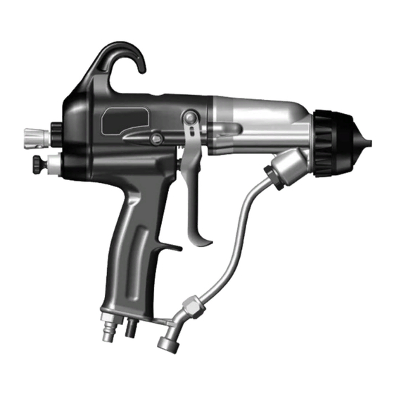
Ranflex Applicators - INTRODUCTION Figure 1: Ransflex Solventborne Electrostatic Spray Applicator 80345 / 80365 RANSFLEX SOLVENTBORNE ELECTROSTATIC SPRAY APPLICATOR 80345 / 80365 Description Description Exhaust Air Hose Needle/Electrode Fluid Hose Barrel Voltage On/Off Switch Handle Trigger Fan Adjustment Compensation Valve Fluid Adjustment Air Cap / Fluid Nozzle Air Hose... -
Page 21: Typical Solvenborne Installation
Ranflex Applicators - INTRODUCTION Figure 2: Ransflex Typical Solventborne Installation RANSFLEX SOLVENTBORNE TYPICAL INSTALLATION Description Description Ransflex 80345 / 80365 Fluid Supply (Grounded) Ball Valve Fluid Regulator Air Regulator with Pressure Gauge Air Hose (79727-XX) Air / Water Separator Air Hose Ground Wire Main Air Supply Line Fluid Line Return To Contents... -
Page 22: Installation
(RH) of the air should be 5%. 1. Operator must make skin contact with handle of 2. Ransburg recommends that a fluid filter be installed applicator. If gloves are required use either gloves at the output of the fluid supply (pressure pot, with palm and finger cut out or conductive gloves. -
Page 23: Installation
Ranflex Applicators - INSTALLATION 2. All objects inside spray area must be grounded - 2. Turn off power. reference EN 50 176 and/or NFPA-33. Resistance to earth ground must be less than 1 meg Ohm. 3. Flammable liquids must be contained in approved metalic grounded containers. -
Page 24: Operation
Ranflex Applicators - OPERATION OPERATION APPLICATOR OPERATION 1. Set fluid pressure using flow regulator. 6.9 bar (100psig) Max 4. Release trigger stop material flow. 1 - Fluid Supply 2 - Flow Regulator 5. Re-connect air supply. 2. Disconnect the air to the applicator. OR... - Page 25 Ranflex Applicators - OPERATION C-31 AIR CAP 80231-00 Static Pressure at Wall Dynamic Pressure at Wall 79727-XX Length psig psig 30 m 20 m 15 m 10 m T-40 AIR CAP 80240-00 Static Pressure at Wall Dynamic Pressure at Wall 79727-XX Length psig psig...
-
Page 26: Flushing / Color Change Procedure
Ranflex Applicators - OPERATION (Horns Vertical) 13. Adjust fan pattern as required. 15. Adjust compensation valve with small driver. NOTE † The compensation valve adjustment is used to adjust fan and atomization pressure at the same time when the pressure to run the turbine is higher than the atomization fan pressure desired. -
Page 27: Fluid Nozzle / Air Cap
Ransflex. 2. Disconnect air to applicator. CAUTION † Nozzles from previous Ransburg design are not compatable with the Ransflex design. Use of these nozzles could cause equipment malfunction and possible damage. -
Page 28: Nozzle Selection
Ranflex Applicators - OPERATION To identify the nozzle, each is engraved with the air cap it must be paired up with. NOZZLE SELECTION 80265-00 / 80264-XX Nozzle Part Number For Use With Air Cap P/N Color Nozzle Opening 80264-07 80265-00 Black 0.7 mm 80264-10... - Page 29 Ranflex Applicators - OPERATION 80231-00 / 80230-XX C SERIES Nozzle Part Number For Use With Air Cap P/N Color Nozzle Opening 80230-12 80231-00 1.2 mm 80230-14 80231-00 Grey 1.4 mm 80230-18 80231-00 Green 1.8 mm 80240-00 / 80239-XX T SERIES Nozzle Part Number For Use With Air Cap P/N Color...
-
Page 30: Air Cap / Nozzle Performance
Ranflex Applicators - OPERATION AIR CAP / NOZZLE PERFORMANCE V-65 - 80265-00 Pattern Orfice ID *Fluid Delivery Pattern Length Width Nozzle Spray Type Pressure Reducer (mm/in) (ml/min) (mm/in) (mm/in) 80264-12 1.2/.047 Air Spray 355/14.0 76/3.0 79809-00 (Yellow) 80264-14 1.4/.055 Air Spray 343/13.5 76/3.0 79809-00 (Yellow) -
Page 31: Maintenance
- MAINTENANCE MAINTENANCE CAUTION CAUTION † Nozzles from previous Ransburg design † NEVER remove the fluid nozzle assembly are not compatable with the Ransflex design. while paint is in the applicator or paint may enter Use of these nozzles could cause equipment into the air passages. - Page 32 Ranflex Applicators - MAINTENANCE • Check that atomizer assembly is clean and undamaged. NOTE † Standard electrode is "snap back" spray wire electrode. • Straighten the applicator electrode if necessary. • Clean the fluid filter, if used. Bi-Yearly • Check air hose resistance. If resistance is greater than .5 MW the hose should be replaced.
- Page 33 Ranflex Applicators - MAINTENANCE 2. Clean and replace as necessary. 3. Install in reverse order. 3. Install fluid nozzle using 80353-00 wrench. Tighten till nozzle seats on O-ring and then 1/8 additional turn. Fluid Nozzle Removal W A R N I N G †...
- Page 34 Ranflex Applicators - MAINTENANCE 2. Remove fluid tube. 2. Carefully disconnect harness by pulling connector on both sides by hand and rocking it side to side to remove. 3. Pull barrel away. 3. Replace cascade as necessary. 4. Apply LSCH 0009 grease to end of cascade. Remove/Replace Cascade 5.
- Page 35 Ranflex Applicators - MAINTENANCE Packing Removal/Replace 5. Remove all parts, clean with non-polar solvent. Inspect for any discolored areas. Replace parts as required. 1. Remove barrel from handle. 2. Use 80353 wrench to remove nut. 6. Prior to installation apply dielectric grease inside packing tube, completely full.
- Page 36 Ranflex Applicators - MAINTENANCE Re-Install Needle Shaft Into Barrel 10. Install Bellville washers in sequence shown. 1. Install needle shaft into barrel with die-electric grease. 11. Install rear nut. Install jam nuts finger tight. 2. Tighten packing using wrench. Pull back and forth on the needle shaft till a slight amount of drag is felt.
- Page 37 Ranflex Applicators - MAINTENANCE Re-Install Barrel 1. Install barrel over cascade. 2. Tighten barrel screws. 3. Re-install fluid tube. 4. Re-install trigger. Return To Contents AH-15-01.2...
- Page 38 Ranflex Applicators - MAINTENANCE Rear Cover/Motor Module Repair Motor Removal 1. Loosen cover screw with 3mm driver. 1. Remove light pipe. 2. Remove fan air cartridge with 10mm wrench. 2. Remove screw and retainer. 3. Remove rear cover and cartridge with 15mm wrench.
- Page 39 Ranflex Applicators - MAINTENANCE Re-assembly 4. Remove porting block. 1. Install porting block on motor. Align screw heads into porting recess. 2. Align motor slots with 3 tab arms. NOTE NOTE † Block must be pulled out with fingers rocking †...
- Page 40 Ranflex Applicators - MAINTENANCE 4. Install screw and retainer. 7. Install gasket and re-connect motor connector to handle harness connector. NOTE † This gasket should be replaced each time the rear cover is dis-assembled. NOTE † Only one way to position 5.
- Page 41 Ranflex Applicators - MAINTENANCE 5. Insert air valve and spring. 10. Tighten cover screw. 6. Tighten packing nut till light drag is felt on the shaft while moving it back and forth. 7. Install rear cover assembly. 8. Install trigger. Air Valve Remove/Replace Fluid Bracket Removal 1.
- Page 42 Ranflex Applicators - MAINTENANCE 6. Tighten fluid nut. 3. Remove bracket, gasket and o-ring. 4. O-ring, gasket and bracket. Gun Wrench Functions 80353-00 1. Adjust packings. 5. Install air fitting. 2. Remove nozzles For V Series For C & T Series Return To Contents AH-15-01.2...
- Page 43 Ranflex Applicators - MAINTENANCE 3. Remove lower fluid nut. 5. Remove rear cartridge. 4. Air fiting. Return To Contents AH-15-01.2...
-
Page 44: Troubleshooting Guide
Ranflex Applicators - MAINTENANCE TROUBLESHOOTING GUIDE General Problem Possible Cause Solution ELECTRICAL On-Off lever in wrong position Ensure the On/Off lever is in the On position. No kV Low pressure Ensure 2.8 bar (40 psig) at the applicator handle with applicator triggered. No ground connection Ensure the air hose is properly grounded to the earth ground. -
Page 45: Parts Identification
Ranflex Applicators - PARTS IDENTIFICATION PARTS IDENTIFICATION RANSFLEX RX - SOLVENT BASE 80345 - ABCDEF Base Optional Model No. Designations ATOMIZATION - TABLE OF “A” DASHES “1” “2” “3” / Color “A” Dash No. “A” Description V SERIES 1.2mm 80265-00 80264-12 79809-00 / YELLOW V SERIES 1.4mm... - Page 46 Ranflex Applicators - PARTS IDENTIFICATION FLUID CONTROL - TABLE OF “B” DASHES “B” Dash No. “B” Description “4” ADJUSTABLE FLUID 80262-00 NON-ADJUSTABLE FLUID 80262-01 TRIGGER - TABLE OF “C” DASHES “C” Dash No. “C” Description “5” 2 FINGER TRIGGER 80211-00 4 FINGER TRIGGER 80386-00* FLUID INLET - TABLE OF “D”...
-
Page 47: Ransflex Rfx Solvent Base
Ranflex Applicators - PARTS IDENTIFICATION RANSFLEX RFX - SOLVENT BASE 80365 - ABCDEF Base Optional Model No. Designations ATOMIZATION - TABLE OF “A” DASHES “1” “2” “3” / Color “A” Dash No. “A” Description V SERIES 1.2mm 80265-00 80264-12 79809-00 / YELLOW V SERIES 1.4mm 80265-00 80264-14... - Page 48 Ranflex Applicators - PARTS IDENTIFICATION FLUID CONTROL - TABLE OF “B” DASHES “B” Dash No. “B” Description “4” ADJUSTABLE FLUID 80262-00 NON-ADJUSTABLE FLUID 80262-01 TRIGGER - TABLE OF “C” DASHES “C” Dash No. “C” Description “5” 2 FINGER TRIGGER 80211-00 4 FINGER TRIGGER 80386-00* FLUID INLET - TABLE OF “D”...
- Page 49 Ranflex Applicators - PARTS IDENTIFICATION Retaining Ring 80377-00 RETAINING RING 80377-00 Qty. Item No. Part No. Description 80377-00 NUT, RETAINING & O-RING ASSEMBLY (CONTAINS ALL PARTS) LSOR0005-17 O-RING, ENCAPSULATED Return To Contents AH-15-01.2...
-
Page 50: Items For Rx (45Kv) Unit
Ranflex Applicators - PARTS IDENTIFICATION ITEMS FOR RX (45KV) UNIT RX 45kV BARREL Item No. Part No. Description Qty. 80376-00 ASSEMBLY, BARREL & O-RING 80263-45 ASSEMBLY, NEEDLE SHAFT 80242-00 NUT, REAR JAM 80243-00 NUT, FRONT JAM 80258-00 SPRING, FLUID RETURN 80250-45 ASSEMBLY, CASCADE RX (45 kV) Barrel and O-Ring P/N 80376-00... -
Page 51: Items For Rx (65Kv) Unit
Ranflex Applicators - PARTS IDENTIFICATION Needle Shaft Assembly 80263-45 RX 45kV NEEDLE SHAFT Qty. Item No. Part No. Description 70430-01 ASSEMBLY ELECTRODE, HIGH WEAR 74653-00 ADAPTER, MALE 14323-00 SEAL, CHEVRON, 3/8 DIA. 14323-00-K4 SEAL, CHEVRON (KIT OF 4) 18821-00 ADAPTER-FEMALE-CHEVRON 80257-45 TUBE, PACKING 80225-45... - Page 52 Ranflex Applicators - PARTS IDENTIFICATION ITEMS FOR RFX (65KV) UNIT RFX 65kV BARREL Qty. Item No. Part No. Description 80379-00 ASSEMBLY, BARREL & O-RING 80263-65 ASSEMBLY, NEEDLE SHAFT 80242-00 NUT, REAR JAM 80243-00 NUT, FRONT JAM 80258-00 SPRING, FLUID RETURN 80250-65 ASSEMBLY, CASCADE RFX (65 kV) Barrel and O-Ring P/N 80379-00...
-
Page 53: Components For All Models
Ranflex Applicators - PARTS IDENTIFICATION Needle Shaft Assembly 80263-65 RFX 65kV NEEDLE SHAFT Qty. Item No. Part No. Description 70430-01 ASSEMBLY, ELECTRODE, HIGH WEAR 74653-00 ADAPTER, MALE 14323-00 SEAL, CHEVRON, 3/8 DIA. 14323-00-K4 SEAL, CHEVRON (KIT OF 4) 18821-00 ADAPTER-FEMALE-CHEVRON 80257-65 TUBE, PACKING 80225-65... - Page 54 Ranflex Applicators - PARTS IDENTIFICATION HANDLE COMPONENTS FOR ALL MODELS HANDLE COMPONENTS Description Qty. Item No. Part No. 80375-00 INCLUDES HANDLE (80305-00) AND REAR COVER WITH MOTOR (80378-00) ASSEMBLY (ADJUSTABLE FLUID CONTROL) 80375-01 INCLUDES HANDLE (80305-01) AND REAR COVER WITH MOTOR (80378-00) ASSEMBLY (NON-ADJUSTABLE FLUID CONTROL) 80245-00 GASKET, BARREL...
- Page 55 Ranflex Applicators - PARTS IDENTIFICATION Handle with Rear Cover with Motor 80375-00/01 HANDLE WITH REAR COVER W/MOTOR 80375-00/01 Qty. Item No. Part No. Description 80305-00 ASSEMBLY, HANDLE 80244-00 ASSEMBLY, VALVE, AIR 80259-00 SPRING, AIR VALVE 80262-00 ASSEMBLY, VALVE, ADJUSTABLE FLUID CONTROL 80262-01 ASSEMBLY, VALVE, NON-ADJUSTABLE FLUID CONTROL 80273-00...
- Page 56 Ranflex Applicators - PARTS IDENTIFICATION Handle Assembly 80305 HANDLE ASSEMBLY 80305 Description Qty. Item No. Part No. 80305-00 ASSEMBLY, HANDLE INCLUDES ALL PARTS BELOW, MOTOR CONTROL BOARD AND HARNESSES 80274-00 SCREW, BARREL-HANDLE 80229-00 NUT, RETAINING, AIR VALVE 10051-05 CUP SEAL, SPRING LOADED Rear Cartridge Assembly 80262-00 (Adjustable Fluid Control) REAR CARTRIDGE ASSEMBLY 80262-00 Qty.
- Page 57 Ranflex Applicators - PARTS IDENTIFICATION Rear Cartridge Assembly 80262-01 (Non-Adjustable Fluid Control) REAR CARTRIDGE ASSEMBLY 80262-01 Qty. Item No. Part No. Description 80262-01 ASSEMBLY, FLUID CARTRIDGE (NON-ADJUSTABLE) 79001-08 O-RING, SOLVENT PROOF 80273-00 Fan Air Cartridge 80273-00 FAN AIR CARTRIDGE Description Qty.
- Page 58 Ranflex Applicators - PARTS IDENTIFICATION 80378-00 Rear Cover with Motor Assembly 80378-00 REAR COVER WITH MOTOR ASSEMBLY Item No. Part No. Description Qty. 80378-00 COVER, REAR ASSEMBLY (INCLUDES ALL PARTS BELOW) 80213-00 PIPE, LIGHT 80255-00 ASSEMBLY, MOTOR 79775-00 BLOCK, PORTING 7554-61 O-RING, SOLVENT RESISTANT 80275-00...
- Page 59 Ranflex Applicators - PARTS IDENTIFICATION 80255-00 Motor Assembly 80255-00 MOTOR ASSEMBLY Qty. Item No. Part No. Description 80255-00 ASSEMBLY, MOTOR (INCLUDES ALL PARTS BELOW) 80217-00 COVER SUPPORT, MOTOR 79796-00 SCREW, MOTOR Return To Contents AH-15-01.2...
-
Page 60: Accessories / Spare Parts Kits
Ranflex Applicators - PARTS IDENTIFICATION 80254-00 Rear Cover Assembly 80254-00 REAR COVER ASSEMBLY Qty. Item No. Part No. Description 80254-00 COVER, REAR (CONTAINS PARTS BELOW) 80274-00 M4 X .7 SHCS Return To Contents AH-15-01.2... -
Page 61: Recommended Spare Parts
Ranflex Applicators - PARTS IDENTIFICATION ACCESSORIES INCLUDED WITH RX OR RFX 79862-02 3mm Hex Driver 80353-00 Gun Wrench LSCH 0009 Grease 80395-00 SPARE PARTS KITS Description Part # 79001-07-K3 Fluid inlet o-ring of barrels 80264-XX-K3 V Series nozzles in kits of 3 (XX = 12, 14 or 18) 80464-XX-K3 V Series high wear nozzles in kits of 3 (XX = 14, 18) 80230-XX-K3... - Page 62 Ranflex Applicators - PARTS IDENTIFICATION RANSFLEX RECOMMENDED SPARE PARTS (Quantities Per Applicator) Part # Description 80264-XX Nozzle, Fluid V Series (See page 42) 80264-XX-K3 Nozzle, Fluid V Series (See page 42) (Kit of 3) 80230-XX Nozzle, Fluid C Series (See page 42) 80230-XX-K3 Nozzle, Fluid C Series (See page 42) (Kit of 3) 80239-XX...
-
Page 63: Warranty Policies
EXCLUSIONS: under normal operating conditions. Normal wear items are excluded. If, in Ransburg’s opinion the warranty item in question, or other items damaged by this part was improperly THE USE OF OTHER THAN RANSBURG APPROVED installed, operated or maintained, Ransburg will assume PARTS, VOID ALL WARRANTIES. - Page 64 Ranflex Applicators - MANUAL CHANGES MANUAL CHANGE SUMMARY Supersede Service Manual AH-15-01 with the following changes: 1. Updated “ATOMIZATION” table “A” — Page 9. 2. Updated “ATOMIZATION” table “A” — Page 12. 3. Updated “AIR CAP/NOZZLE PERFORMANCE” table — Page 27. 4.
- Page 65 Ransburg Manufacturing 1910 North Wayne Street Angola, Indiana 46703-9100 Telephone: 260-665-8800 Fax: 260-665-8516 Technical Service — Assistance 320 Philips Ave. Toledo, Ohio 43612-1493 Telephone (toll free): 800-233-3366 Fax: 419-470-2233 Technical Support Representative will direct you to the appropriate telephone number for ordering Spare Parts.
Need help?
Do you have a question about the RansFlex RX 80345 and is the answer not in the manual?
Questions and answers