Table of Contents
Advertisement
Quick Links
Advertisement
Table of Contents

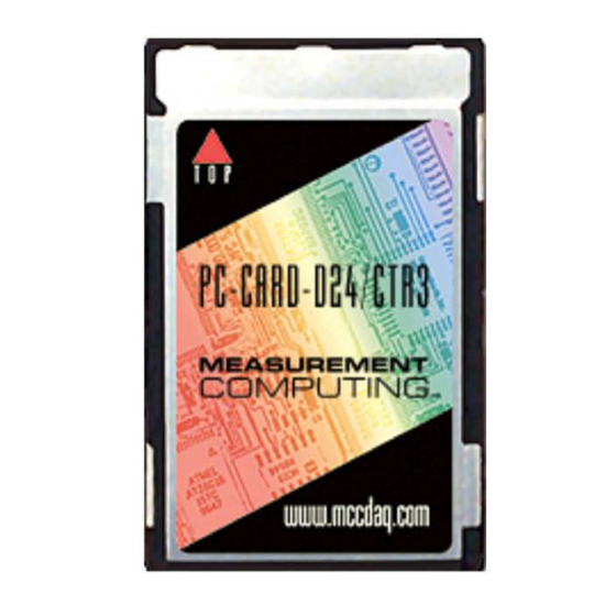
Summary of Contents for Measurement Computing PC-CARD-D24/CTR3
- Page 2 PC-CARD-D24/CTR3 Digital I/O and Counter Board User’s Guide Document Revision 6, April, 2007 © Copyright 2007, Measurement Computing Corporation...
- Page 3 © 2007 Measurement Computing Corporation. All rights reserved. No part of this publication may be reproduced, stored in a retrieval system, or transmitted, in any form by any means, electronic, mechanical, by photocopying, recording, or otherwise without the prior written permission of Measurement Computing Corporation.
-
Page 5: Table Of Contents
Overview: PC-CARD-D24/CTR3 features ......................7 PC-CARD-D24/CTR3 block diagram ..........................7 Software features ..............................7 Chapter 2 Installing the PC-CARD-D24/CTR3 ......................8 What comes with your PC-CARD-D24/CTR3 shipment? .................8 Hardware ..................................8 Additional documentation..............................8 Optional components ................................ 8 Unpacking the PC-CARD-D24/CTR3 .......................9 Installing the software ............................9 Installing the PC-CARD-D24/CTR3........................9... -
Page 6: Preface
Italic text is used for the names of manuals and help topic titles, and to emphasize a word or phrase. Where to find more information Additional information about PC-CARD-D24/CTR3 hardware is available on our website at www.mccdaq.com. You can also contact Measurement Computing Corporation with specific questions. -
Page 7: Introducing The Pc-Card-D24/Ctr3
Introducing the PC-CARD-D24/CTR3 Overview: PC-CARD-D24/CTR3 features The PC-CARD-D24/CTR3 is a data acquisition and control board for IBM PC compatible computers with PCMCIA/PC-CARD type slots. The primary functional elements consist of the following: An 82C55 chip using TTL logic for 24 bi-directional digital I/O channels. -
Page 8: Installing The Pc-Card-D24/Ctr3
In addition to this hardware user's guide, you should also receive the Quick Start Guide (available in PDF at www.mccdaq.com/PDFs/manuals/DAQ-Software-Quick-Start.pdf). This booklet supplies a brief description of the software you received with your PC-CARD-D24/CTR3 and information regarding installation of that software. Please read this booklet completely before installing any software or hardware. -
Page 9: Unpacking The Pc-Card-D24/Ctr3
Fax: 508-946-9500 to the attention of Tech Support Email: techsupport@mccdaq.com Installing the software Refer to the Quick Start Guide for instructions on installing the software on the Measurement Computing Data Acquisition Software CD. This booklet is available in PDF at www.mccdaq.com/PDFs/manuals/DAQ- Software-Quick-Start.pdf. -
Page 10: Connecting The Board For I/O Operations
CIO-TERM100 SCB-50 SSR-RACK24 CIO-ERB24 CIO-SERB24 Pin out – main I/O connector Figure 3 shows a PC-CARD-D24/CTR3 case looking into the male mini-connector. The connector is mechanically keyed to insure that the cable is inserted correctly. Figure 3. 50-pin I/O mini-connector... - Page 11 PC-CARD-D24/CTR3 User's Guide Installing the PC-CARD-D24/CTR3 Cabling Measurement Computing offers two cables for connecting the PC-CARD-D24/CTR3 to a screw-type terminal board or other signal conditioning interface board: The CPCC-50F-39 cable: 39 inches (990 mm) long; and compatible with standard 50-pin screw terminal products.
- Page 12 PC-CARD-D24/CTR3 User's Guide Installing the PC-CARD-D24/CTR3 Figure 6 shows a map of the two methods of cabling the PC-CARD-D24/CTR3 to various screw terminal or signal conditioning boards. RELAYS TERMINALS CIO-MINI50 SSR-RACK24 PC-CARD-D24/CTR3 CIO-SPADE 50 CIO-ERB24 CIO-TERM100 CIO-SERB24 C50FF-# SCB-50 CPCC-50M-4...
- Page 13 PC-CARD-D24/CTR3 User's Guide Installing the PC-CARD-D24/CTR3 CPCC-50M-4 If your application requires a cable that is longer than one meter in length, use the CPCC-50M-4 four-inch cable, and connect to a C50FF-x cable. 50-pin micro connector. Connect to the I/O connector 50-pin male IDC connector.
-
Page 14: Field Wiring And Signal Termination
Signal Connections (available at www.mccdaq.com/pdfs/DAQ-Signal-Connections.pdf). Calibrating the PC-CARD-D24/CTR3 No calibration is required. There are no socketed or user-serviceable parts in the PC-CARD-D24/CTR3. The case cannot be opened. Opening the case will void your warranty. If your PC-CARD-D24/CTR3 requires service, contact the factory for an RMA# and return it... -
Page 15: Programming And Developing Applications
Programming languages Measurement Computing’s Universal Library provides access to board functions from a variety of Windows programming languages. If you are planning to write programs, or would like to run the example programs for ... -
Page 16: Chapter 4 Specifications
Chapter 4 Specifications Typical for 25 °C unless otherwise specified. Specifications in italic text are guaranteed by design. Digital input/output Table 1. Digital I/O specifications Digital type 82C55 Configuration 2 banks of 8, 2 banks of 4, programmable by bank as input or output Number of channels 24 I/O Output high... -
Page 17: Power Consumption
PC-CARD-D24/CTR3 User's Guide Specifications Crystal oscillator Frequency: 10 MHz Frequency accuracy: 50 ppm Miscellaneous: Available (divided by 10) at user connector (1 MHz Out) Power consumption Table 3. Power consumption specifications +5V operating 45 mA typical, 65 mA max Miscellaneous Table 4. - Page 18 PC-CARD-D24/CTR3 User's Guide Specifications Table 7. Connector pin out Signal Name Signal Name Ext Int Int Enable CTR1 CLK CTR1 Gate CTR1 Out CTR2 CLK CTR2 Gate CTR2 Out CTR3 CLK CTR3 Gate CTR3 Out 1 MHz Out...
- Page 19 Norton, MA 02766 Category: Electrical equipment for measurement, control and laboratory use. Measurement Computing Corporation declares under sole responsibility that the product PC-CARD-D24/CTR3 to which this declaration relates is in conformity with the relevant provisions of the following standards or...
- Page 20 Measurement Computing Corporation 10 Commerce Way Suite 1008 Norton, Massachusetts 02766 (508) 946-5100 Fax: (508) 946-9500 E-mail: info@mccdaq.com www.mccdaq.com...


Need help?
Do you have a question about the PC-CARD-D24/CTR3 and is the answer not in the manual?
Questions and answers