
Related Manuals for Measurement Computing PCIe-DIO24


Summary of Contents for Measurement Computing PCIe-DIO24
- Page 1 PCIe-DIO24 Digital Input/Output User's Guide Document Revision 2A September 2014 © Copyright 2014...
- Page 2 Other product and company names mentioned herein are trademarks or trade names of their respective companies. © 2014 Measurement Computing Corporation. All rights reserved. No part of this publication may be reproduced, stored in a retrieval system, or transmitted, in any form by any means, electronic, mechanical, by photocopying, recording, or otherwise without the prior written permission of Measurement Computing Corporation.
-
Page 3: Table Of Contents
About this User's Guide ........................4 Conventions in this user's guide ......................... 4 Where to find more information ......................... 4 Chapter 1 Introducing the PCIe-DIO24 ......................... 5 Overview: PCIe-DIO24 features ........................5 Functional block diagram ........................... 6 Chapter 2 Installing the PCIe-DIO24 ........................7 What comes with your shipment? ........................ -
Page 4: Preface
Phone: 508-946-5100 and follow the instructions for reaching Tech Support If you need to program at the register level in your application, refer to the Register Map for the PCIe-DIO24. This document is available on our website at www.mccdaq.com/registermaps/RegMapPCIe-DIO24.pdf. -
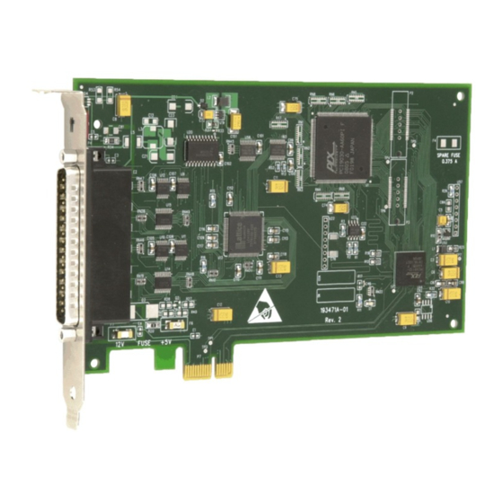
Page 5: Introducing The Pcie-Dio24
PCI Express (PCIe) bus. The PCIe-DIO24 provides 24 lines of digital I/O with selectable 3.3 V and 5 V logic levels. The 24 DIO lines are organized into three groups of 8-bits each (Port A, Port B, and Port C). Port C can be further divided into two four-bit ports (Port C-HI and Port C-LO). -
Page 6: Functional Block Diagram
PCIe-DIO24 User's Guide Introducing the PCIe-DIO24 Functional block diagram PCIe-DIO24 functions are illustrated in the block diagram shown here. +12V Regulated Fuse +12V Protection Spare Fuse (pin 16) and 12V Fuse 1.5V 3.3V 3.3V 3.3V Board Power Protection Regulator (pin 18) -
Page 7: Installing The Pcie-Dio24
As with any electronic device, you should take care while handling to avoid damage from static electricity. Before removing the PCIe-DIO24 from its packaging, ground yourself using a wrist strap or by simply touching the computer chassis or other grounded object to eliminate any stored static charge. -
Page 8: Installing The Hardware
Insert the PCIe-DIO24 into an unused x1 PCIe expansion slot. The PCIe-DIO24 is designed to install into an x1 slot. However, you can also install the board into an unused x4, x8, or x16 PCIe slot. -
Page 9: Cabling
PCIe-DIO24 User's Guide Installing the PCIe-DIO24 Logic level switch +V * 20 IRQ INPUT GND 21 IRQ ENABLE PORT C7 22 PORT B7 PORT C6 23 PORT B6 PORT C5 24 PORT B5 PORT C4 25 PORT B4 PORT C3 26... -
Page 10: Field Wiring And Signal Termination
Figure 4. C37FFS-x cable Field wiring and signal termination You can use the following MCC screw terminal boards and relay racks with the PCIe-DIO24 board using the C37FF-x or C37FFS-x cable: SCB-37 – 37-conductor, shielded signal connection/screw terminal box that provides two independent 37- ... -
Page 11: Functional Details
Unconnected inputs will float in the pull direction that is configured for the port with InstaCal (either up/high or down/low). Replacing a fuse The PCIe-DIO24 has two individual 0.375 amp slow blow fuses. One fuse is connected to the 12V output at pin 16, and is labeled on the board. The second fuse is connected to both +V... -
Page 12: Specifications
Chapter 4 Specifications All specifications are subject to change without notice. Typical for 25 °C unless otherwise specified. Digital input/output Table 1. Digital I/O specifications Parameter Specification Digital type 82C55 Emulation Configuration 2 banks of 8, 2 banks of 4, programmable by bank as input or output Ports A and B: 74HC245A Output... -
Page 13: Environmental
PCIe-DIO24 User's Guide Specifications Environmental Table 3. Environmental specifications Parameter Specification Operating temperature range 0 °C to 50 °C Storage temperature range –20 °C to 70 °C Humidity 0% to 90% non-condensing Mechanical Table 4. Environmental specifications Parameter Specification Dimensions (L × W × H) 167.4 ×... - Page 14 PCIe-DIO24 User's Guide Specifications Table 7. Signal connector pinout Signal Name Signal Name IRQ INPUT (Note 1) IRQ ENABLE Port B7 Port C7 Port B6 Port C6 Port B5 Port C5 Port B4 Port C4 Port B3 Port C3 Port B2...
-
Page 15: Declaration Of Conformity
Electrical equipment for measurement, control and laboratory use. Date and Place of Issue: September 12, 2014, Norton, Massachusetts USA Measurement Computing Corporation declares under sole responsibility that the product PCIe-DIO24 Complies with the essential requirements of the following applicable European Directives:... - Page 16 Measurement Computing Corporation 10 Commerce Way Suite 1008 Norton, Massachusetts 02766 (508) 946-5100 Fax: (508) 946-9500 E-mail: info@mccdaq.com www.mccdaq.com...
Need help?
Do you have a question about the PCIe-DIO24 and is the answer not in the manual?
Questions and answers