Table of Contents
Advertisement
Quick Links
Advertisement
Table of Contents

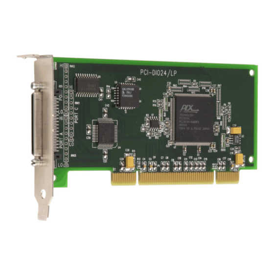
Summary of Contents for Measurement Computing PCI-DIO24/LP
- Page 2 PCI-DIO24/LP Digital Input/Output User's Guide Document Revision 7, May, 2009 © Copyright 2009, Measurement Computing Corporation...
- Page 3 Management committed to your satisfaction! Thank you for choosing a Measurement Computing product—and congratulations! You own the finest, and you can now enjoy the protection of the most comprehensive warranties and unmatched phone tech support. It’s the embodiment of our mission: ...
- Page 4 Information furnished by Measurement Computing Corporation is believed to be accurate and reliable. However, no responsibility is assumed by Measurement Computing Corporation neither for its use; nor for any infringements of patents or other rights of third parties, which may result from its use. No license is granted by implication or otherwise under any patent or copyrights of Measurement Computing Corporation.
-
Page 5: Table Of Contents
Overview: PCI-DIO24/LP features ........................7 Software features ..............................7 Chapter 2 Installing the PCI-DIO24/LP ........................8 What comes with your PCI-DIO24/LP shipment? ..................... 8 Hardware ..................................8 Additional documentation ..............................8 Optional components ................................ 8 Unpacking the PCI-DIO24/LP ........................... 9 Installing the software ............................ -
Page 6: Preface
What you will learn from this user's guide This user's guide explains how to install, configure and use the PCI-DIO24/LP digital I/O board. This user's guide also refers you to related documents available on our web site and to technical support resources. -
Page 7: Introducing The Pci-Dio24/Lp
Introducing the PCI-DIO24/LP Overview: PCI-DIO24/LP features This manual explains how to install, configure and use the PCI-DIO24/LP digital I/O board. You can use the PCI-DIO24/LP to control logic devices such as switches, gauges, relays, pumps, and sensors in a variety of digital applications. -
Page 8: Installing The Pci-Dio24/Lp
Cables C68MMS-x Signal termination and conditioning accessories MCC provides signal termination and conditioning boards that you can use with the PCI-DIO24/LP. Refer to the "Field wiring, signal termination and conditioning" section on page 10 for a complete list of... -
Page 9: Unpacking The Pci-Dio24/Lp
As with any electronic device, you should take care while handling to avoid damage from static electricity. Before removing the PCI-DIO24/LP from its packaging, ground yourself using a wrist strap or by simply touching the computer chassis or other grounded object to eliminate any stored static charge. -
Page 10: Pin Out - Main I/O Connector
Figure 1. C68MMS-x cable Field wiring, signal termination and conditioning You can connect the PCI-DIO24/LP to the following screw terminal board using the C68MMS-x cable. CIO-MINI68 – 68-pin screw terminal board. Details on this product is available on our web site at... -
Page 11: Chapter 3 Functional Details
For general information about digital signal connections and digital I/O techniques, refer to the Guide to Signal Connections (available on our web site at www.mccdaq.com/signals/signals.pdf). Caution! Do not connect high current/voltage devices directly to the PCI-DIO24/LP or you may damage the board. -
Page 12: Signal Level Control
0 V (low logic level). The PCI-DIO24/LP has open locations where you can install a 2.2 K , eight-resistor single inline package (SIP) resistor network for each port. The SIP is made up of eight 2.2 K resistors. One side of each resistor is connected to a single common point and brought out to a pin. - Page 13 PCI-DIO24/LP User's Guide Functional Details +5 VDC +5 VDC Dot indicates the 2.2 K SIP common line 2.2 K SIP Digital Digital I/O Port I/O Port n = A, B, or C n = A, B, or C (GND) (GND)
-
Page 14: Chapter 4 Specifications
Chapter 4 Specifications Typical for 25 °C unless otherwise specified. Specifications in italic text are guaranteed by design. Digital input/output Table 1. Digital I/O specifications Digital type 82C55 Number of I/O 24 (Port A0 through Port C7) Configuration 2 banks of 8 and 2 banks of 4 or 3 banks of 8 or 2 banks of 8 with handshake Input low voltage... -
Page 15: Mechanical
PCI-DIO24/LP User's Guide SpecificationsError! No text of specified style in document. Mechanical Table 5. Mechanical specifications Card dimensions PCI low-profile MD2 length: 131.8 mm (L) x 63.5 mm (W) x 18.4 mm (H) Form factor Universal PCI keying. Compatible with either 3.3 V or 5 V PCI signaling environments. -
Page 16: Declaration Of Conformity
Norton, MA 02766 Category: Electrical equipment for measurement, control and laboratory use. Measurement Computing Corporation declares under sole responsibility that the product PCI-DIO24/LP to which this declaration relates is in conformity with the relevant provisions of the following standards or other documents: EC EMC Directive 2004/108/EC: General Requirements, EN 61326-1:2006 (IEC 61326-1:2005). - Page 17 Measurement Computing Corporation 10 Commerce Way Suite 1008 Norton, Massachusetts 02766 (508) 946-5100 Fax: (508) 946-9500 E-mail: info@mccdaq.com www.mccdaq.com...


Need help?
Do you have a question about the PCI-DIO24/LP and is the answer not in the manual?
Questions and answers