ProSoft Technology RadioLinx RLX2-IHW User Manual
Industrial, rlx2-ihx series, 802.11a, b, g, n, fast / high power / weatherproof ip66/67
Hide thumbs
Also See for RadioLinx RLX2-IHW:
- User manual (208 pages) ,
- User manual (100 pages) ,
- User manual (161 pages)

Related Manuals for ProSoft Technology RadioLinx RLX2-IHW


Summary of Contents for ProSoft Technology RadioLinx RLX2-IHW
- Page 1 RLX2-IHx Series 802.11a, b, g, n Industrial Hotspots 802.11abg, RLX2-IHW 802.11abgn, Fast, RLX2-IHNF 802.11g, High Power, RLX2-IHG 802.11a, High Power, RLX2-IHA 802.11abgn, Weatherproof IP66/67, RLX2-IHNF-W/WC June 15, 2015 USER MANUAL...
-
Page 2: Content Disclaimer
Neither ProSoft Technology nor any of its affiliates or subsidiaries shall be responsible or liable for misuse of the information contained herein. Information in this document including illustrations, specifications and dimensions may contain technical inaccuracies or typographical errors. -
Page 3: Important Safety Information
Important Safety Information The following Information and warnings pertaining to the radio module must be heeded: WARNING – EXPLOSION HAZARD – DO NOT REPLACE ANTENNAS UNLESS POWER HAS BEEN SWITCHED OFF OR THE AREA IS KNOWN TO BE NON-HAZARDOUS. "THIS DEVICE CONTAINS ONE OF THE FOLLOWING TRANSMITTER MODULES: FCC ID: OQ7IHG, RYK-WMIA199NI, NKRDCMA82, SWX-XR5 PLEASE SEE FCC ID LABEL ON BACK OF DEVICE."... -
Page 4: Rlx2-Ihnf, Rlx2-Iha, Rlx2-Ihg, Rlx2-Ihw
RLX2-IHNF, RLX2-IHA, RLX2-IHG, RLX2-IHW 1. This equipment is Suitable For Use in Class I, Division2, Groups A, B, C, D or Non-Hazardous Location Only. 2. WARNING – EXPLOSION HAZARD – Substitution of Any Components May Impair Suitability for Class I, Division 2. 3. -
Page 5: Recommended Antennas
5. The equipment shall be properly grounded with the external ground screw provided connected to building ground as well as the antenna coaxial screen of the connector shall be grounded. 6. Device must be powered by a Class 2 Power Source. 7. -
Page 6: Antenna Spacing Requirements For User Safety
A2412NJ3-DP 12dBi Panel N-Jack MIMO antenna 2.4GHz A2413NJ-DP 13 dBi Directional patch panel N jack with mounting hardware 2.4GHz A2415NJ-DY 15 dBi Directional N jack Yagi with mounting hardware 2.4GHz A2416NJ-DS 16 dBi Directional 120 degree sector N jack with mounting hardware 2.4GHz A2419NJ-DB 19 dBi Directional N jack parabolic with mounting hardware 2.4GHz A2419NJ-DP... -
Page 7: Table Of Contents
Contents ............................2 EEDBACK LEASE ............................2 OW TO ONTACT ............................. 2 ONTENT ISCLAIMER ..........................3 MPORTANT AFETY NFORMATION Industry Canada Requirements: ........................3 RLX2-IHNF, RLX2-IHA, RLX2-IHG, RLX2-IHW....................4 RLX2-IHNF-W..............................4 RLX2-IHNF-WC .............................. 4 Recommended Antennas ..........................5 Antenna Spacing Requirements for User Safety ......................6 START HERE .............................. - Page 8 ........................57 EST THE ETWORK NSTALLATION DIAGNOSTICS AND TROUBLESHOOTING ....................... 59 ............................... 60 IAGNOSTICS ........................... 61 HECK THE THERNET ABLE LED D ................................ 62 ISPLAY .......................... 63 ETRIEVE THE EFAULT ASSWORD RLX2-IHNF-W and RLX2-IHNF-WC Reset ...................... 63 Resetting All Other Radios ........................... 64 IH B ......................
- Page 9 RLX2-IHNF DFS S ..........................123 UPPORT Master Radio Operations .......................... 123 DFS Auto Select ............................124 RADIOLINX INDUSTRIAL HOTSPOT BROWSER ..................... 125 ..........................126 RIMARY ADIO UNCTIONS ............................... 127 Scan Setup ..............................127 Scan ................................128 Clear ................................128 Import ............................... 128 Export ................................
- Page 10 Print Area ..............................149 Reset Columns ............................150 Select Columns ............................150 ............................... 150 Help Topics ..............................151 About RLX IH Browser ..........................152 RLX2 VIRTUAL LAN (VLAN) FUNCTIONALITY ....................153 VLAN T (802.1Q) ....................153 RANSPARENT UPPORT OF VLAN T ................
- Page 11 Approved Antennas in Europe/CE .......................... 188 Approved Antennas in Mexico ..........................189 Approved Antennas with Power Amp ........................189 Antenna Location, Spacing, and Mounting ....................190 SUPPORT, SERVICE & WARRANTY ....................... 191 ........................191 ONTACTING ECHNICAL UPPORT Warranty Information ..........................192 GLOSSARY OF TERMS ..........................
-
Page 13: Start Here
Different models operating on common frequencies can communicate with each other. Furthermore, most RLX2 series radios (except RLX2-IHNF) can communicate with ProSoft Technology’s legacy RLXIB series of radios. Details on the specific differences between the RLX2 and RLXIB series products can be found in the Compatibility with ProSoft RLXIB Series Radios section on page 159. -
Page 14: About The Radiolinx ® Rlx2 Industrial Hotspot™ Products
Signal Strength LEDs: SD card inserted Alternates green and amber if SD card with new configuration inserted Signal Strength LEDs: running in Client or No Signal Repeater Modes Page 14 of 212 ProSoft Technology, Inc. June 15, 2015... - Page 15 See section 0 for further details regarding the LED display for various conditions. Antenna Ports Each RLX2 series radio has active antenna connectors on the top as shown below: RLX2-IHA RLX2-IHG These radios have a single active antenna port: ProSoft Technology, Inc. Page 15 of 212 June 15, 2015...
- Page 16 This radio has three active antenna ports: RLX2-IHNF-W-A (FCC) RLX2-IHNF-W-E (ETSI) These two radios represent the weatherproof versions for the RLX2-IHNF. Three antennas perform the same functions as those on the RLX2-IHNF. Page 16 of 212 ProSoft Technology, Inc. June 15, 2015...
- Page 17 This version represents a weatherproof, hazardous location radio. It is a conduit version and is Class I, DIV 2 compliant. Three antennas perform the same functions as those in the RLX2-IHNF-W-A and RLX2-IHNF-W-E. ProSoft Technology, Inc. Page 17 of 212 June 15, 2015...
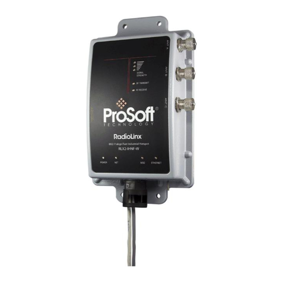
- Page 18 RLX2-IHW This radio uses the right-side antenna port for transmit and receive. An optional receive-only antenna can be attached to the left-side antenna port to improve performance in some applications. Page 18 of 212 ProSoft Technology, Inc. June 15, 2015...
-
Page 19: Package Contents
CULPWR-M12-033 33 foot Power Cable 33 foot (10m), M12 to unterminated leads, Power CUPLWR-M12-010 10 foot Power Cable Cable 10 foot (3m), M12 to unterminated leads, Power Cable ProSoft Technology, Inc. Page 19 of 212 June 15, 2015... -
Page 20: Standard Contents (Rlx2-Ihnf-Wc)
2 dBi Omni RP-SMA articulating, 2.4/5GHz. This antenna is suitable for all RLX2 radio products. ProSoft Solutions DVD Contains sample programs, utilities, firmware DVD-001 ® images, and documentation for RadioLinx products. Page 20 of 212 ProSoft Technology, Inc. June 15, 2015... -
Page 21: Industrial Hotspot Bench Test Kit (Rlx-Ihbtk)
Note: The RLX2-IHNF-W and WC do not have a Personality Module. Important: Before installing, please verify all listed product items are present. If any of these components are missing, please contact ProSoft Technology Support for replacements. ProSoft Technology, Inc. Page 21 of 212... -
Page 22: The Radiolinx Industrial Hotspot Browser Configuration Tool
An internet connection may be useful to download updated product information from the ProSoft Technology website at http://www.ProSoft-Technology.com. Installation from DVD 1. Insert the ProSoft Solutions DVD in the DVD drive. On most computers, a menu screen will open automatically. - Page 23 6. The DVD should display a startup screen like this: 7. Type the product name into the search box and click Search. Here is an example of searching for the RLX2-IHNF: ProSoft Technology, Inc. Page 23 of 212 June 15, 2015...
- Page 24 8. Click on the Product Name. The screen displays the contents for this module. 9. Double-click on RadioLinx IH Browser v3.4 (or a newer version if available) and the installation wizard should launch: Page 24 of 212 ProSoft Technology, Inc. June 15, 2015...
-
Page 25: Installation From Download File
Double–click the zip file after downloading. The Windows extraction wizard will extract the installation file (RadioLinx IH Browser 3.130.msi or a newer version.) Then double-click the .msi file to install the IH Browser. ProSoft Technology, Inc. Page 25 of 212 June 15, 2015... -
Page 27: Rlx2 Quick Setup
Master. IMPORTANT: If a ProSoft Power adapter RL-PS007-2 (supplied with the RLX-IHBTK Bench Test Kit) is not present, see instructions on wiring the power connector in this manual. ProSoft Technology, Inc. Page 27 of 212 June 15, 2015... -
Page 28: Setup Master Radio
1. Attach an Ethernet cable with an M12 connector to the specified port shown on the designated Master RLX2 radio. Make sure that this network connection is on the same subnet as the PC running the IH Browser configuration software. Page 28 of 212 ProSoft Technology, Inc. June 15, 2015... - Page 29 Most off-the-shelf PoE Injectors work with this unit except for the 802.3at/ PoE+ Injectors. Note: The M12 PoE cable is not included with the radio but can be ordered through ProSoft. ProSoft Technology, Inc. Page 29 of 212 June 15, 2015...
-
Page 30: For Rlx2-Ihnf-Wc Radios
2. Run both wires down through the conduit. 3. Push the conduit up into the permanently installed connector on the bottom of the radio. Push it up as far as it will go. Page 30 of 212 ProSoft Technology, Inc. June 15, 2015... - Page 31 RLX2 Industrial Hotspot Series Note: Recommend conduit is Thomas & Betts® PMA Series, Cat. No. CYLT-23B. ProSoft Technology, Inc. Page 31 of 212 June 15, 2015...
- Page 32 In the event that you have to remove the conduit, simply remove the Oval Clip using a screwdriver to pry it out. The conduit can now be removed from the Connector. Page 32 of 212 ProSoft Technology, Inc. June 15, 2015...
- Page 33 If you are using PoE to provide power to the module, the additional power cables should be terminated inside the junction box during installation to prevent the wire assembly from shorting out. WARNING: Do not connect or disconnect the PoE connection when energized. ProSoft Technology, Inc. Page 33 of 212 June 15, 2015...
- Page 34 RLX2 Industrial Hotspot Series Page 34 of 212 ProSoft Technology, Inc. June 15, 2015...
-
Page 35: For All Other Radios
The MAC address should be something like 00-0D-8D-XX- YY-ZZ (e.g. 00-0D-8D-F0-5C-8E.) This number uniquely identifies the radio on the network. 3. Run the IH Browser configuration software. ProSoft Technology, Inc. Page 35 of 212 June 15, 2015... - Page 36 5. Assign the RLX2 a valid IP address for the network. Do this by right-clicking on the radio’s row in the IH Browser display and selecting Assign IP from the context menu. Page 36 of 212 ProSoft Technology, Inc. June 15, 2015...
- Page 37 7. The Access Point utility warns you of the temporary selection. 8. Click OK. 9. Open a web browser on the PC, and enter the IP address that was just assigned to the radio (e.g. http://192.168.1.250). A login screen opens: ProSoft Technology, Inc. Page 37 of 212 June 15, 2015...
- Page 38 10. The radio’s main webpage opens: (Some fields may be different depending on the specific radio model). 11. Select the Master radio button and select Channel 1 (2412 MHz) as shown in the following example. Page 38 of 212 ProSoft Technology, Inc. June 15, 2015...
- Page 39 Note: Select Channel 36 (5180 MHz) if the Master radio is an RLX2-IHA. 12. If the IP address is manually set as previously described, permanently set the IP address by selecting the Use the following IP address radio button: ProSoft Technology, Inc. Page 39 of 212 June 15, 2015...
- Page 40 13. Click the Apply Changes button and the Radio reboots. A progress bar is visible during reboot. Upon successful reboot, the RLX2 radio is shown as a Master in the IH Browser window: Page 40 of 212 ProSoft Technology, Inc. June 15, 2015...
- Page 41 RLX2 Industrial Hotspot Series ProSoft Technology, Inc. Page 41 of 212 June 15, 2015...
-
Page 42: Setup Repeater Radio
After setting the Repeater’s IP address, remove its Ethernet connection. 4. On the PC, open a command prompt window and attempt to ping the Repeater’s IP address. The Master should ping the Repeater over the air: Page 42 of 212 ProSoft Technology, Inc. June 15, 2015... - Page 43 RLX2 Industrial Hotspot Series 5. Congratulations! The RLX2 wireless network is now configured. Additional Repeaters can be configured by repeating the steps listed above. ProSoft Technology, Inc. Page 43 of 212 June 15, 2015...
-
Page 44: Setup Client Radio
1. Connect the client radio to the same network as the configuration PC running the IH browser. Assign it an IP address as described above. Open the configuration webpage and change the radio to Client mode as shown: Page 44 of 212 ProSoft Technology, Inc. June 15, 2015... - Page 45 Ensure the IP address of the Ethernet interface on the PC is on the same subnet as the network of the Client Radio. For this example, set the IP address of the PC interface to 192.168.1.100. Here is an example of doing so in Windows 7: ProSoft Technology, Inc. Page 45 of 212 June 15, 2015...
-
Page 46: Install Replacement Radio Using Personality Module
If the radio being installed is replacing an existing radio, and a Personality Module was already installed in the existing radio, then no manual configuration is necessary. Remove the Personality Module from the existing radio with the stored configuration Page 46 of 212 ProSoft Technology, Inc. June 15, 2015... -
Page 47: Planning The Network
Choose the appropriate antennas for the network. If an antenna will be connected to the radio by a long cable, a power amplifier (available from ProSoft Technology) may be needed. The more distance between an antenna and its radio, the more signal loss the radio will have. - Page 48 Make sure the plan complies with the radio’s power requirements and cable specifications. Important: Radios and antennas must be located at least 8 inches (20 cm) away from personnel. Page 48 of 212 ProSoft Technology, Inc. June 15, 2015...
-
Page 49: Installation Questions
ProSoft Wireless Designer is a freely-available software tool to simplify the task of specifying a ProSoft wireless installation. The following screenshot shows an example of configuring wireless links and estimates of signal quality: ProSoft Technology, Inc. Page 49 of 212 June 15, 2015... - Page 50 RLX2 Industrial Hotspot Series Page 50 of 212 ProSoft Technology, Inc. June 15, 2015...
- Page 51 Customers can use this information to understand and visualize their network, and provide necessary information for technical support and maintenance. ProSoft Technology, Inc. Page 51 of 212 June 15, 2015...
-
Page 52: Functional Specifications
When using the downloaded application from the ProSoft website, it is packaged as a zip archive. Double-click the zip archive to extract the installation file I NSTALLER double-click it to start the installation. Page 52 of 212 ProSoft Technology, Inc. June 15, 2015... -
Page 53: Personality Module Configuration Restoration
This feature reduces the time to replace a damaged radio by eliminating the need to manually configure the replacement radio. Consideration of how to use this feature in advance of installation is necessary to take advantage of this feature. ProSoft Technology, Inc. Page 53 of 212 June 15, 2015... - Page 54 Physical security of the radios and the MicroSD card is highly recommended. If the Personality Module feature will not be used, it is recommended that you turn Auto-Clone and Auto-Write off. Page 54 of 212 ProSoft Technology, Inc. June 15, 2015...
-
Page 55: Installing The Radios
The temporary placement of the antenna can be by hand. However, with this testing method, one person must hold the antenna while another monitors the radio’s signal strength. ProSoft Technology, Inc. Page 55 of 212 June 15, 2015... - Page 56 It may be near the bottom of the window. Scroll down to view all available radios. To change how radios link to the network, see Parent Link settings (page 82). Refer to Improve Signal Quality (page 66) for more information on overcoming poor connectivity. Page 56 of 212 ProSoft Technology, Inc. June 15, 2015...
-
Page 57: Connecting Antennas
Remote radio's signal strength displayed on the Configuration PC. To improve the signal quality of each Remote radio: Increase the height of the antenna's placement Use higher-gain antennas ProSoft Technology, Inc. Page 57 of 212 June 15, 2015... - Page 58 Determine and resolve sources of "electrical" noise which may be interfering with the radio transmission Add a repeater between the radios that are not communicating, or reconfigure an existing radio as a repeater if line of sight is available Page 58 of 212 ProSoft Technology, Inc. June 15, 2015...
-
Page 59: Diagnostics And Troubleshooting
You can perform the following troubleshooting routines: Check the Ethernet cable (page 61) Retrieve the default password (page 63) For more troubleshooting information, go to the ProSoft Technology web site at www.prosoft-technology.com ProSoft Technology, Inc. Page 59 of 212 June 15, 2015... -
Page 60: Diagnostics
Retrieve the default password (page 63) Troubleshoot IH Browser error messages (page 65) Troubleshoot missing radios in the IH Browser (page 65) For more troubleshooting information, visit the ProSoft Technology website at www.prosoft-technology.com. Page 60 of 212 ProSoft Technology, Inc. June 15, 2015... -
Page 61: Check The Ethernet Cable
Ethernet patch cable is connected between the injector and switch. Note: The RLX2 radio auto-detects the Ethernet connection type, and does not require a crossover cable for direct connection to a PC. ProSoft Technology, Inc. Page 61 of 212 June 15, 2015... -
Page 62: Led Display
ETHERNET LED will not (because the ping packet was not transmitted over the air) Blinks if SD card with new configuration inserted Reserved for future additional use. Blinks if SD card with new configuration inserted Reserved for future additional use. Page 62 of 212 ProSoft Technology, Inc. June 15, 2015... -
Page 63: Retrieve The Default Password
RLX2-IHNF-W and RLX2-IHNF-WC Reset 1. Remove power from the radio. 2. Press the Reset button. The Reset button is located on the front of the unit just under the ProSoft logo. ProSoft Technology, Inc. Page 63 of 212 June 15, 2015... -
Page 64: Resetting All Other Radios
To retrieve the default password and return the radio to its default settings: Turn off power to the radio. Locate the reset button hole. Insert the end of a paperclip or similar device into the hole to press the reset button. Page 64 of 212 ProSoft Technology, Inc. June 15, 2015... -
Page 65: Troubleshoot Ih Browser Error Messages
Windows ETWORK CONNECTIONS Control Panel, then open the L window and verify OCAL ONNECTION ROPERTIES that the check box under I is not checked. NTERNET ONNECTION IREWALL ProSoft Technology, Inc. Page 65 of 212 June 15, 2015... -
Page 66: Improve Signal Quality
Select a new location for the radio and/or its antenna. Decrease the length of the antenna cable. Determine and resolve sources of interfering electrical noise. Add a repeater between radios that are not communicating. Page 66 of 212 ProSoft Technology, Inc. June 15, 2015... -
Page 67: Detailed Radio Configuration / Diagnostics
RadioLinx Industrial Hotspot radio. Open a web browser. In the address bar, type " ", followed by the IP address for the radio, and http:// then click the "Go" button. For example, http://192.168.6.10 ProSoft Technology, Inc. Page 67 of 212 June 15, 2015... -
Page 68: Read-Only Fields
Configuration Help Help is available for each item in the Radio Configuration / Diagnostic Utility. Page 68 of 212 ProSoft Technology, Inc. June 15, 2015... - Page 69 To view more help about the selected field, click the field name. This action opens a help page in a new browser window. ProSoft Technology, Inc. Page 69 of 212 June 15, 2015...
- Page 70 RLX2 Industrial Hotspot Series Page 70 of 212 ProSoft Technology, Inc. June 15, 2015...
- Page 71 To view the complete online documentation for the RLX2 radio, click the button. This action opens the online documentation in a new browser window. Use the Contents, Index and Search tabs in the left frame to navigate the help system. ProSoft Technology, Inc. Page 71 of 212 June 15, 2015...
-
Page 72: Radio Status
The length of time that the radio has been continuously connected to parent Link Time radio. Strength of the signal from the Parent radio. Signal Strength MAC address of the parent radio to which the selected radio is linked. Parent MAC Page 72 of 212 ProSoft Technology, Inc. June 15, 2015... -
Page 73: Available Parents
This page is helpful for viewing: Possible parents for a repeater. The current parent should normally be the radio with the lowest cost and a matching SSID. Other 802.11 networks in the area. ProSoft Technology, Inc. Page 73 of 212 June 15, 2015... - Page 74 A cost is calculated for each entry and can be seen in the column labeled "Cost" in the preceding table. The cost calculation is based not only on the strongest signal, but on several other factors to provide optimum network communication. Page 74 of 212 ProSoft Technology, Inc. June 15, 2015...
-
Page 75: Address Table
The length of time (in seconds) since the radio last saw a packet from this Age (s) MAC address Click the Top button to see the top of the table. The radio will display updated data in the table entries. ProSoft Technology, Inc. Page 75 of 212 June 15, 2015... -
Page 76: Port Status
The primary reason for creating a Spanning Tree to that is allows you to create fully redundant paths. If any single radio in a redundant path loses its connection, another path still exists, and the connection will be updated and communication restored. Page 76 of 212 ProSoft Technology, Inc. June 15, 2015... - Page 77 Amethyst_BD. This link is shown with a red dotted line. Also visible is the level of redundancy in their network. Each of the blue lines represents an alternate parent. From this view, it is easily shown how much redundancy exists in their network. ProSoft Technology, Inc. Page 77 of 212 June 15, 2015...
-
Page 78: Radio Network Settings
Radio Network Settings Note: Different versions of the RLX2 Radios support different functionality. The may be more or fewer options on this page, depending on the version of the radio. Page 78 of 212 ProSoft Technology, Inc. June 15, 2015... - Page 79 Assign a Network name (SSID) of up to 32 characters. The radio uses this Network SSID name in all network references. All radios in a network must have the same SSID. SSID names are case-sensitive. ProSoft Technology, Inc. Page 79 of 212 June 15, 2015...
- Page 80 Master in a network. You must have at least one Master radio per network. For redundancy, you can assign more than one Master to a network. For information, see Redundancy. Page 80 of 212 ProSoft Technology, Inc. June 15, 2015...
- Page 81 See QoS Settings in this section. Opens the Spanning Tree Settings form. Spanning Tree Opens the Advanced Settings form. Advanced Config Opens the Roam Control Settings Roam Control ProSoft Technology, Inc. Page 81 of 212 June 15, 2015...
-
Page 82: Parent Link Settings
Hop Count - Fewer hops from the Master radio is given preference and therefore a lower cost Choose this setting to allow the radio to determine the best parent to select. Page 82 of 212 ProSoft Technology, Inc. June 15, 2015... - Page 83 Parent and another candidate, with the caveat of course, that a roam point exists where the RSSI difference between the current Parent and the new Parent is greater than this margin. ProSoft Technology, Inc. Page 83 of 212 June 15, 2015...
- Page 84 Discards the changes without updating the radio configuration. Cancel After a selection is saved and return to the Radio Network Settings panel, notice the selection is indicated under the Parent Link button. Page 84 of 212 ProSoft Technology, Inc. June 15, 2015...
-
Page 85: Prioritized Parent Selection
Prioritized Parent Selection If more control is needed than the automatic algorithm allows, a priority list of parents for the RLX2 radio can be defined. Prioritized Parent by Branch Length ProSoft Technology, Inc. Page 85 of 212 June 15, 2015... - Page 86 Master radio. If Branch Length of 2 is chosen, the radio will link only to an RLX2 radio that is linked to the Master radio, and so on. Prioritized Parent by Preferred Parent List Page 86 of 212 ProSoft Technology, Inc. June 15, 2015...
- Page 87 Follow List Priority The radio will select its parent from the list giving preference to the first entry, followed by the second entry, and so on. ProSoft Technology, Inc. Page 87 of 212 June 15, 2015...
-
Page 88: Igmp Settings
802.11 BSS created by each RLX2 allowing client devices to associate. The VLAN settings for the Ethernet interface are settable on all RLX2 radios. The VLAN settings for Page 88 of 212 ProSoft Technology, Inc. June 15, 2015... - Page 89 When this function is enabled, packets received by the RLX2 on an interface that are not VLAN tagged are assigned to the VLAN as set by the PVID parameter of the respective interface. ProSoft Technology, Inc. Page 89 of 212 June 15, 2015...
-
Page 90: Qos Settings
The QoS Settings Page allows you to set the Default Priority for frames received without any priority markings. In addition, you can map a priority value to packets received without priority according to a set of match criteria. Page 90 of 212 ProSoft Technology, Inc. June 15, 2015... - Page 91 Ethernet interface that are not marked with a priority value. This control enables or disables the priority mapping function of the RLX2. QoS Map Enable When enabled, the priority mapping table becomes editable. ProSoft Technology, Inc. Page 91 of 212 June 15, 2015...
-
Page 92: Rapid Spanning Tree Functionality
RTSP uses active communications between network devices to propagate changes in the network and to cause transitions to occur much more quickly. Because RTSP is an IEEE Page 92 of 212 ProSoft Technology, Inc. June 15, 2015... - Page 93 Each of these states takes at least 15 seconds, during which the STP devices are listening for BPDUs to re-negotiate the network topology. The advantage of using the RSTP functionality is that is uses ProSoft Technology, Inc. Page 93 of 212 June 15, 2015...
- Page 94 Until the learning is complete, the packets are broadcast to their destination. As each packet is seen and the switch table rebuilds, the radios return to directing packets to their destinations. Page 94 of 212 ProSoft Technology, Inc. June 15, 2015...
-
Page 95: Spanning Tree Settings
If for some reason a BPDU is received on this port, the RSTP protocol will negotiate properly and handle any possible redundant paths. The recommended setting for Ethernet Edge Port is "Enabled". ProSoft Technology, Inc. Page 95 of 212 June 15, 2015... - Page 96 Also, because all radios are repeaters, each radio can be configured to reach a master radio via multiple repeater paths. If a repeater goes down, the linked radios can use a different path to get back to a master radio. Page 96 of 212 ProSoft Technology, Inc. June 15, 2015...
-
Page 97: Advanced Settings
This results in improved network performance. The settings on this form also allow the configuration of the transmission rate and broadcast mode to optimize this radio's use on an industrial network. ProSoft Technology, Inc. Page 97 of 212 June 15, 2015... - Page 98 Normally, the Max Data Rate should be set to the maximum value. The above example shows this setting MCS15. The default maximum is 54 MBits/s. However, under poor operating conditions, reliability may improve if the Max Data Rate is reduced. Page 98 of 212 ProSoft Technology, Inc. June 15, 2015...
- Page 99 Radio Network Settings section of the main webpage. See section 0. Throughput in 802.11n wide mode is approximately twice that of 802.11n mode. ProSoft Technology, Inc. Page 99 of 212 The radio will automatically select the Guard Interval (GI) based on...
- Page 100 Long range is 25km, which is valid for all operating modes of all radios. Reducing the range setting for systems at closer range may improve throughput. Sets the output power of the radio. TX Power Attenuation Page 100 of 212 ProSoft Technology, Inc. June 15, 2015...
- Page 101 Previous Configuration files are renamed with a unique file name which allows auditing of changes made to the unit's settings. ProSoft Technology, Inc. Page 101 of 212 June 15, 2015...
-
Page 102: Roam Control
The lowest cost determines when a better Parent candidate is present. There are several limitations when the RLX2s are operating in autonomous roam mode that can be overcome by using Parent Assisted Roaming. Page 102 of 212 ProSoft Technology, Inc. June 15, 2015... - Page 103 The following settings allow for Parent Assisted roaming by advertising these parameter values to any Child Repeater that associates to this unit. Each parameter can be enabled separately using a checkbox. Only enabled parameters are advertised to Child Repeaters. ProSoft Technology, Inc. Page 103 of 212 June 15, 2015...
- Page 104 The Child Repeater uses this threshold to determine when to switch to the Next Parent’s channel an associate with it. The installer must ensure that at a point Page 104 of 212 ProSoft Technology, Inc. June 15, 2015...
-
Page 105: Security Settings
Security panel will automatically change to selections applicable to the selected mode. Note: The controls will change to allow you to fully configure the Security Settings before Applying the Changes. ProSoft Technology, Inc. Page 105 of 212 June 15, 2015... - Page 106 Note: Newer firmware versions of the RLX2 Radios may support additional functionality. Therefore, you may see more or fewer options on this page, depending on the version of firmware included the radio you purchased. The following security settings can be configured: Page 106 of 212 ProSoft Technology, Inc. June 15, 2015...
- Page 107 Hides the Network SSID (Network Name) from other 802.11 users. Clients Hide Network SSID (page can connect to the "hidden" network by typing the Network SSID. 114) ProSoft Technology, Inc. Page 107 of 212 June 15, 2015...
-
Page 108: Encryption Type
63 normal keyboard characters. This phrase automatically generates an encryption key of 128 hexadecimal characters. This field is only available if you select one of the ‘Personal’ security modes. The default WPA-AES Phrase is 'passphrase'. Page 108 of 212 ProSoft Technology, Inc. June 15, 2015... -
Page 109: Enterprise Mode Settings
RLX2 and the RADIUS server. The only authentication option available for EAP-TLS is to use TLS for the inner protocol. EAP-TTLS – EAP Tunneled TLS. Similar to EAP-PEAP. Anonymous ID: ProSoft Technology, Inc. Page 109 of 212 June 15, 2015... -
Page 110: Certificate Management
The IT person will provide you with the appropriate files that you’ll need to load to the RLX2 Repeater. The following controls are used for uploading a certificate: Page 110 of 212 ProSoft Technology, Inc. June 15, 2015... -
Page 111: Configuring The Rlx2 Repeaters With Certificates
RLX2 Repeater. 1. Open the web page for the RLX2 repeater that you want to configure. 2. Select the EAP Method (PEAP or EAP-TLS). 3. Enter the Username. ProSoft Technology, Inc. Page 111 of 212 June 15, 2015... -
Page 112: Wep Key
To create a 128-bit key, enter 13 normal text characters, which convert to 26 hex digits, or enter 26 hex digits (0 to 9, a to f, A to F) directly. Page 112 of 212 ProSoft Technology, Inc. June 15, 2015... - Page 113 Finally, change to the desired transmit key number if necessary and save again (If "****" remains in the key field, the previously programmed key will not be changed when changes are applied) ProSoft Technology, Inc. Page 113 of 212 June 15, 2015...
-
Page 114: Mac Filter
SSID check box in each radio to be hidden. With the SSID hidden, the network does not show up when other clients scan for an access point. Clients can still connect to the "hidden" network by typing the Network SSID. Page 114 of 212 ProSoft Technology, Inc. June 15, 2015... -
Page 115: Radio Access Settings
Use an IP address that will not interfere with any other devices on the IP Address network. Request a block of IP addresses to use from the Network Administrator. ProSoft Technology, Inc. Page 115 of 212 June 15, 2015... - Page 116 Access Points, or for radios that must be accessible through a firewall. A detailed discussion of TCP/IP networking is beyond the scope of this manual. Refer to the following Microsoft knowledgebase article for more information: http://support.microsoft.com/kb/164015 Page 116 of 212 ProSoft Technology, Inc. June 15, 2015...
-
Page 117: Snmp Agent Settings
RFC12133-MIB (partial; internet.mgmt.MIB-2.system, .interfaces, .snmp) ROMAP-MIB (included on the DVD; internet.private.enterprises.romap) It also supports a selection of standard SNMP traps, including Cold Start, which is sent when the radio initializes. ProSoft Technology, Inc. Page 117 of 212 June 15, 2015... -
Page 118: Serial Settings
This configuration page opens when the Serial Port Settings button is clicked on the Radio Configuration form. Use this page to configure the way serial data packets are encapsulated and transmitted over an Ethernet network. Page 118 of 212 ProSoft Technology, Inc. June 15, 2015... - Page 119 Available delineation types are: Decimal Description Type Any string of characters Use Text Carriage Return Escape Line Feed (New Line / nl) Null Null Space Spacebar Horizontal Tab ProSoft Technology, Inc. Page 119 of 212 June 15, 2015...
- Page 120 Stop bits (1 or 2). The stop bits on the radio must match the stop bits on the Stop Bits connected serial device. Saves the changes and updates the radio configuration. Save Discards the changes without updating the radio configuration. Cancel Page 120 of 212 ProSoft Technology, Inc. June 15, 2015...
-
Page 121: Change Password
Any alphanumeric value between one and 31 characters can be entered. The password is case-sensitive. If the password cannot be found, changes the radio settings cannot be done. To revert back to the default password, see the Troubleshooting section. ProSoft Technology, Inc. Page 121 of 212 June 15, 2015... -
Page 122: Apply Changes
Click the Factory Defaults button to reset the radio to the default settings. Important: This action discards all the radio configuration settings. A prompt to confirm this action will appear before changes take place. Page 122 of 212 ProSoft Technology, Inc. June 15, 2015... -
Page 123: Rlx2-Ihnf Dfs Support
Channel Availability Check Time before it can begin to transmit. If the newly-selected channel is not a DFS channel, or if the channel was previously monitored for radar since the radio was powered on, transmissions can begin immediately. ProSoft Technology, Inc. Page 123 of 212 June 15, 2015... -
Page 124: Dfs Auto Select
One of the Master channel selection options is DFS Auto Selec With this selection the radio randomly selects a DFS channel for operation. The actual channel in operation is always shown in the Current Channel display: Page 124 of 212 ProSoft Technology, Inc. June 15, 2015... -
Page 125: Radiolinx Industrial Hotspot Browser
To clear all the radios from the list, click the Erase button in the tool bar or select Clear from the File menu. Refreshing the list is done by clicking Scan. If there is trouble viewing radios in the IH Browser, see Troubleshoot missing radios (page 65). ProSoft Technology, Inc. Page 125 of 212 June 15, 2015... -
Page 126: Primary Radio Functions
Properties (page 139): View the selected radio’s properties. In addition, there are more options in the File menu. Print either a list of the radios' properties or a topology view. Page 126 of 212 ProSoft Technology, Inc. June 15, 2015... -
Page 127: File Menu
Broadcasts are limited to a local network, and will not be passed through a router. ProSoft Technology, Inc. Page 127 of 212 June 15, 2015... -
Page 128: Scan
Print Prints the contents of the IH Browser window. Depending on the view selected, the radio properties or a topology view can be printed. Page 128 of 212 ProSoft Technology, Inc. June 15, 2015... -
Page 129: Print Preview
The following commands are available on the Operations Menu: Connect (page 130) Assign IP (page 54, page 131) Update Firmware (page 132) Start Ping Session (page 132) ProSoft Technology, Inc. Page 129 of 212 June 15, 2015... -
Page 130: Connect
IH Browser after it has been assigned an IP address (either manually or with DHCP). Alternatively, the Connect option in the AP Operations menu can be selected. Enter the password to log in to the radio. Page 130 of 212 ProSoft Technology, Inc. June 15, 2015... -
Page 131: Assign Ip
IP address can be entered (see Radio Access settings (page 115)). After an IP address is assigned, configuring the radios can be done in the Radio Configuration / Diagnostic Utility (page 66). ProSoft Technology, Inc. Page 131 of 212 June 15, 2015... -
Page 132: Update Firmware
Ping Device A Ping Session allows traffic to run over the radio network between any two computers running the IH Browser. With it the user can monitor their network over time. Page 132 of 212 ProSoft Technology, Inc. June 15, 2015... -
Page 133: Ping Options Dialog Box
The Ping Options dialog box opens from the Show Options button on the Ping Results (page 132) dialog box. Use this dialog box to choose ping parameters, logging options, and response to other stations. ProSoft Technology, Inc. Page 133 of 212 June 15, 2015... -
Page 134: Dialogs Menu
This dialog box opens when the Wireless Clients option is selected from the AP Dialogs menu. Use this dialog box to see information about wireless clients attached to the radio. Page 134 of 212 ProSoft Technology, Inc. June 15, 2015... -
Page 135: Ethernet Nodes
ID) attached to the Ethernet port of Tourmaline_14. In addition to the IP and MAC ID it gives an age for each entry, which is the amount of time since a packet has been heard from that device. ProSoft Technology, Inc. Page 135 of 212 June 15, 2015... -
Page 136: Scan List
The scan list is a list of all the radios that this particular radio "hears" on this channel (via beacons) even if it is not linked to it (different SSID or encryption). This list shows the Page 136 of 212 ProSoft Technology, Inc. June 15, 2015... -
Page 137: 802.11 Access Point Detector
Port status (page 76) list in the Radio Configuration / Diagnostic Utility. Each radio can have up to 34 active ports—one Ethernet cable, one parent RF link, and up to 32 child RF links. ProSoft Technology, Inc. Page 137 of 212 June 15, 2015... -
Page 138: All 4 Dialogs
The event log allows the extraction of a log from the selected radio. The log shows a history of the radio. The event log can be saved to a file for troubleshooting purposes. Page 138 of 212 ProSoft Technology, Inc. June 15, 2015... -
Page 139: Event Filter
Properties This dialog box opens when a radio is selected the Properties option is selected from the AP Dialogs menu. To see additional properties, click the More button. ProSoft Technology, Inc. Page 139 of 212 June 15, 2015... -
Page 140: View Menu
Zoom to Fit (page 148) Show Ping Stations (page 148) Show Parents (page 149) Print Area (page 149) Reset Columns (page 150) Select Columns (page 150) Toolbar Page 140 of 212 ProSoft Technology, Inc. June 15, 2015... -
Page 141: Status Bar
There are many columns of data that can be displayed. Columns can be hidden as needed. Use Select Columns from the View Menu to choose the columns of data to display. ProSoft Technology, Inc. Page 141 of 212 June 15, 2015... - Page 142 All ProSoft devices have a MAC address of the form 00:0D:8D:XX:YY:ZZ IP address assigned to the device. Netmask of the device. Mask IP address of the network gateway for the device. Gateway Page 142 of 212 ProSoft Technology, Inc. June 15, 2015...
- Page 143 For wired network interfaces, this is the version of the Boot Ver network communication engine in the IH Browser (e.g. WinXP, WinVista.) For radios, this is the version of the bootloader code in the radio. ProSoft Technology, Inc. Page 143 of 212 June 15, 2015...
- Page 144 The amount of time the device has been running since the Uptime last power cycle or reset. For example 1d,4h,13m,25s. The type of RLX2 radio. The values can be RLX2-IHA, RLX2- Product IHG, RLX2-IHFN, or RLX2-IHW. Page 144 of 212 ProSoft Technology, Inc. June 15, 2015...
-
Page 145: Topology View
Refer to Topology View key (page 145) for an explanation of the symbols that appear in this view. Topology View Key For information on the options when right-clicking a radio icon, see IH Browser options. ProSoft Technology, Inc. Page 145 of 212 June 15, 2015... - Page 146 Wireless clients (PCMCIA cards) are linked to this radio; the number of clients linked is indicated by the number of boxes Signal strength; the width of the line is not calibrated Alternate parents. Page 146 of 212 ProSoft Technology, Inc. June 15, 2015...
-
Page 147: Zoom In
Topology View to enlarge the size of the items in the IH Browser window. Zoom Out Use the Z command in Topology View to reduce the size of the items in the IH- Browser window. ProSoft Technology, Inc. Page 147 of 212 June 15, 2015... -
Page 148: Zoom To Fit
Ping Stations are other computers running an instance of IH Browser. To test latency between points on the network, select a ping station, open the Operations menu, and then choose Start Ping Session. Page 148 of 212 ProSoft Technology, Inc. June 15, 2015... -
Page 149: Show Parents - All
This is similar to Show Parents – All except that only the current parent is shown. Print Area Use the Print Area command to show the border around the area of the IH Browser window. To print, use the Print command on the File menu. ProSoft Technology, Inc. Page 149 of 212 June 15, 2015... -
Page 150: Reset Columns
A prompt will appear to confirm this action. Select Columns Use the Select Columns command to display the data fields shown in List View. Help Menu The Help menu contains the following commands: Page 150 of 212 ProSoft Technology, Inc. June 15, 2015... -
Page 151: Help Topics
The Index button shows an index of keywords. Type the first few letters of a keyword to jump directly to a topic. Each keyword is linked to one or more help topics. ProSoft Technology, Inc. Page 151 of 212 June 15, 2015... -
Page 152: About Rlx Ih Browser
RLX2 Industrial Hotspot Series About RLX IH Browser Use this command to view version information about the IH Browser. This information may be needed when contacting ProSoft Technical Services. Page 152 of 212 ProSoft Technology, Inc. June 15, 2015... -
Page 153: Rlx2 Virtual Lan (Vlan) Functionality
Port/Radio-based VLAN tagging with Managed Switches Port/Radio-based VLAN tagging without Managed Switches Transparent Support of VLAN Tags (802.1Q) The following provides an example of transparent communication between Managed Switches using VLAN trunking. ProSoft Technology, Inc. Page 153 of 212 June 15, 2015... -
Page 154: Port/Radio-Based Vlan Tagging With Managed Switches
PLC, Drive, and HMI communicate on VLAN 1 and with the Control Network (same subnet) Mobile worker communicates to the SCADA network only (VLAN 2). The laptop communicates to Internet/Business Network only (VLAN 3) Page 154 of 212 ProSoft Technology, Inc. June 15, 2015... -
Page 155: Port/Radio-Based Vlan Tagging Without Managed Switches
802.1Q frames. The wireless network also supports Radio to Radio VLANs using one or more Trunk Links. PLC, Drive & HMI communicate on one VLAN on the same subnet Mobile Worker/Laptop communicate with a fixed server on VLAN 2 (separate subnet). ProSoft Technology, Inc. Page 155 of 212 June 15, 2015... - Page 156 RLX2 Industrial Hotspot Series Page 156 of 212 ProSoft Technology, Inc. June 15, 2015...
-
Page 157: Reference
A high level of security is inherent with AES (Advanced Encryption Standard) encryption. TKIP (Temporal Key Integrity Protocol) is also available. If necessary, adding WEP128 or WEP64 (Wired Equivalent Protocol) encryption in addition to AES or TKIP for clients that ProSoft Technology, Inc. Page 157 of 212 June 15, 2015... - Page 158 Firmware updates can be done at anytime from anywhere on the network. This includes over the wireless link or over the Internet. ProSoft Technology radios can easily be installed into new or existing systems. The software and manuals can be downloaded from the DVD or ProSoft Technology’s web site at www.prosoft-technology.com.
-
Page 159: Compatibility With Prosoft Rlxib Series Radios
1.06 lbs 1.06 lbs 1.1 lbs (499g) (499g) (499g) (499g) (499g) (479g) (479g) Typical Power < 9W 5.7W < 9W 4.5W < 6 W 4.5W 7.1W Consumption Max Power Consumption ProSoft Technology, Inc. Page 159 of 212 June 15, 2015... - Page 160 5 GHz band DFS channels Use RLXIB Firmware Image Use RLX2 Firmware Image Page 160 of 212 ProSoft Technology, Inc. June 15, 2015...
-
Page 161: Dimensional Drawings
RLX2 Industrial Hotspot Series Dimensional Drawings ProSoft Technology, Inc. Page 161 of 212 June 15, 2015... - Page 162 RLX2 Industrial Hotspot Series Page 162 of 212 ProSoft Technology, Inc. June 15, 2015...
-
Page 163: Master Channel-Frequency Table
2462 2467 2472 5180 5200 5220 ProSoft Technology, Inc. Page 163 of 212 June 15, 2015... - Page 164 136 (DFS) 5680 140 (DFS) 5700 5745 5765 5785 5805 5825 Page 164 of 212 ProSoft Technology, Inc. June 15, 2015...
-
Page 165: Fcc Emission Regulations
Maximum Power From Radio Maximum Antenna Maximum EIRP Gain 1000 2.4 GHz Band, Point-To-Point Maximum Power From Radio Maximum Antenna Maximum EIRP Gain 1000 10.0 16.0 25.0 39.8 63.0 100.0 158.0 ProSoft Technology, Inc. Page 165 of 212 June 15, 2015... -
Page 166: Ghz Bands, Point-To-Multipoint
UNII-2 5.470 – 100, 104, Indoor or Extended 5.725 108, 112, Outdoor 116, 120, 124, 128, 132, 136, UNII-3 5.725 – 149, 153, Typical 1000 4000 5.825 157, 161, Outdoor Page 166 of 212 ProSoft Technology, Inc. June 15, 2015... -
Page 167: Radio Hardware
RLX2 Industrial Hotspot Series Radio Hardware Radio Power Requirements (RLX2-IHNF-W) These cables are available for purchase from ProSoft Technology: Description ProSoft Part Number Power Cable, 3m (7 ft), M12 to un- CULPWR-M12-010 terminated leads Power Cable, 10m (33 ft), M12 to un-... - Page 168 Important: When wiring the power connector supplied with the radio, be sure to observe the proper polarity markings on the power connector. Wiring the connector incorrectly can cause serious damage to the radio which will not be covered under the ProSoft warranty. Page 168 of 212 ProSoft Technology, Inc. June 15, 2015...
- Page 169 To use the installation tool, insert it into the connector as shown: Press down on the installation tool to use it as a level which will open the connector’s contacts to insert a wire. A properly-wired power connector is shown: ProSoft Technology, Inc. Page 169 of 212 June 15, 2015...
- Page 170 Using Power over Ethernet (PoE) to power remote devices has several advantages including: "Carrier Class" Power Over Ethernet System. Power can be supplied over long distances, up to 300 feet. Page 170 of 212 ProSoft Technology, Inc. June 15, 2015...
-
Page 171: Ethernet Cable Specifications
RJ45 connectors on the other. These are PoE cables and you can purchase directly from ProSoft Technology: Description ProSoft Part Number Network Cable, 2m (7 ft) M12 to RJ45 CURJ45-M12-007 Network Cable, 10m (33 ft) M12 to RJ45 CURJ45-M12-033 ProSoft Technology, Inc. Page 171 of 212 June 15, 2015... - Page 172 This PoE cable contains an M12 (IP65, IP67) connector on one end that attaches to the radio. The other end contains an RJ45 connector for a network connection or power injector. Pin Assignments M12 socket, 8-pos, A-coded, female RJ45 pin assignment Circuit Diagram Page 172 of 212 ProSoft Technology, Inc. June 15, 2015...
-
Page 173: Ethernet Cable Configuration (All Other Radios)
3 Tx+ 3 Rx+ 6 Tx- 6 Rx- Crossover Cable RJ-45 Pin RJ-45 Pin 1 Rx+ 3 Tx+ 2 Rx- 6 Tx- 3 Tx+ 1 Rx+ 6 Tx- 2 Rx- ProSoft Technology, Inc. Page 173 of 212 June 15, 2015... -
Page 174: Rlx2-Iha Detailed Specifications
Up to 100% RH, with no condensation Humidity 10 Vdc to 24 Vdc External Power 48 Vdc PoE Injector 802.3af Compliant Power over Ethernet Less than 7 Watts Average Power Page 174 of 212 ProSoft Technology, Inc. June 15, 2015... -
Page 175: Agency Approvals & Certifications
1 to 13 (ETSI) WPA2 - 802.11i with 128 bit AES-CCM Security Legacy WPA TKIP, WEP support MAC ID filter Admin password Physical Extruded aluminum with DIN and panel mount Enclosure ProSoft Technology, Inc. Page 175 of 212 June 15, 2015... -
Page 176: Agency Approvals & Certifications
52, 56, 60, 64 5.470 GHz to 5.725 GHz (FCC/ETSI) 100, 104, 108, 112, 116*, 132, 136, 140* 5.725 GHz to 5.850 GHz (FCC) 149, 153, 157, 161, *DFS channels with RADAR detection Page 176 of 212 ProSoft Technology, Inc. June 15, 2015... - Page 177 29.2 x 17.8 x 7 cm (H x W x D) (RLX2-IHNF-W and WC) 11.5 x 7 x 2.75 in (H x W x D) IEC 60068 2-6 (20g, 3-Axis) Shock IEC 60068 2-27 (5g, 10Hz to 150Hz) Vibration ProSoft Technology, Inc. Page 177 of 212 June 15, 2015...
-
Page 178: Agency Approvals & Certifications
Visit www.prosoft-technology.com for current wireless approval information. Hazardous Locations Regulatory CSA/CB Safety UL/cUL; Class I, Div 2 CE Mark Ex Certificate (ATEX Directive, Zone 2) FCC: OQ7SR71A IC: 5265A-SR71A ETSI Page 178 of 212 ProSoft Technology, Inc. June 15, 2015... -
Page 179: Rlx2-Ihw Detailed Specifications
One 10/100/1000 Base-T connector, shielded RJ45 Ethernet Ports (2) RP-SMA connectors Antenna Ports 1.06 lbs (479g) Weight Environmental Operating Temperature -40°C to +75°C (-40°F to +167°F) Up to 100% RH, with no condensation Humidity ProSoft Technology, Inc. Page 179 of 212 June 15, 2015... -
Page 180: Agency Approvals & Certifications
Agency Approvals & Certifications Wireless Approvals Visit www.prosoft-technology.com for current wireless approval information. Hazardous Locations Regulatory CSA/CB Safety UL/cUL; Class1, Div 2 CE Mark Ex Certificate (ATEX Directive, Zone 2) FCC/IC ETSI Page 180 of 212 ProSoft Technology, Inc. June 15, 2015... -
Page 181: Antenna Configuration
Connecting antennas to the radio, see Connecting Antennas Consider important electrical characteristics when selecting antennas: Antenna pattern Antenna gain Antenna polarity Antenna location, spacing, and mounting ProSoft Technology, Inc. Page 181 of 212 June 15, 2015... -
Page 182: Control Drawing
RLX2 Industrial Hotspot Series Control Drawing Page 182 of 212 ProSoft Technology, Inc. June 15, 2015... -
Page 183: Antenna Pattern
A slice taken in a horizontal plane through the center (or looking down on the pattern) is called the azimuth pattern. A view from the side reveals a vertical plane slice called the elevation pattern. ProSoft Technology, Inc. Page 183 of 212 June 15, 2015... -
Page 184: Antenna Gain
On the other hand, if the transmit antenna has vertical polarization and the receiving antenna has horizontal polarization, no power should be received. If the two antennas have Page 184 of 212 ProSoft Technology, Inc. June 15, 2015... -
Page 185: Whip Antennas
It is fed in on one end. The antenna pattern is torroidal. Its azimuthal beamwidth is 360° (omnidirectional). Its vertical beamwidth depends on the number of elements/length, where more elements ProSoft Technology, Inc. Page 185 of 212 June 15, 2015... -
Page 186: Yagi Array Antenna
Power is radiated from the feed antenna toward the reflector. Due to the parabolic shape, the reflector concentrates the radiation into a narrow pattern, resulting in a high- gain beam. Page 186 of 212 ProSoft Technology, Inc. June 15, 2015... -
Page 187: Rlx2 Approved Antennas
In the U.S. and Canada, use antennas that are specifically approved by the U.S. Federal Communications Commission (FCC) and Industry Canada for use with the RLX2 radios. Contact ProSoft Technology or visit www.prosoft-technology.com for a current list of approved antennas. -
Page 188: Approved Antennas In Europe/Ce
Note: In France, the user is responsible for ensuring that the selected frequency channels comply with French regulatory standards. At the time of this printing, only channels 10 through 13 can be used in France. Page 188 of 212 ProSoft Technology, Inc. June 15, 2015... -
Page 189: Approved Antennas In Mexico
22H x 12.7 Patch* Directional 13 dB N-RP 22H x 22 28 cm Patch* Directional 14 dB N-RP 81L x 9.0 28 cm Yagi* * Only allowed in a point-to-point network. ProSoft Technology, Inc. Page 189 of 212 June 15, 2015... -
Page 190: Antenna Location, Spacing, And Mounting
Position directional antennas so they do not point at nearby antennas. Place antennas side by side if they point in the same direction. Place antennas back to back if they point in opposite directions. Page 190 of 212 ProSoft Technology, Inc. June 15, 2015... -
Page 191: Support, Service & Warranty
E R V I C E A R R A N T Y Contacting Technical Support ProSoft Technology, Inc. (ProSoft) is committed to providing the most efficient and effective support possible. Before calling, please gather the following information to assist in expediting this process:... -
Page 192: Warranty Information
(located in Sao Paulo) Languages spoken include: Portuguese, English Warranty Information For complete details regarding ProSoft Technology’s TERMS & CONDITIONS OF SALE, WARRANTY, SUPPORT, SERVICE AND RETURN MATERIAL AUTHORIZATION INSTRUCTIONS please see the documents on the Product DVD or go to www.prosoft-... -
Page 193: Glossary Of Terms
Wireless network framework in which devices can communicate directly with one another without using an AP or a connection to a regular network. RLX2 radio products do not support Ad hoc mode. ProSoft Technology, Inc. Page 193 of 212 June 15, 2015... - Page 194 802.1x-authenticated network. Band Another term for spectrum used to indicate a particular set of frequencies. Wireless networking protocols work in either the 2.4 GHz or the 5 GHz bands. Page 194 of 212 ProSoft Technology, Inc. June 15, 2015...
- Page 195 Typically 10 seconds. Client, Radio Mode A radio in Client mode can connect to any Access Point, but can only support one Ethernet device. See also Repeater, Radio Mode. ProSoft Technology, Inc. Page 195 of 212 June 15, 2015...
- Page 196 Also known as a peer-to-peer network. DFS stands for Dynamic Frequency Selection, a requirement for operation on certain frequencies in the 5 GHz band in many countries. When a radio operates on a DFS Page 196 of 212 ProSoft Technology, Inc. June 15, 2015...
- Page 197 (that evenly distributes power in all directions and is a theoretical construct) to produce the peak power density observed in the direction of maximum antenna gain. ProSoft Technology, Inc. Page 197 of 212 June 15, 2015...
- Page 198 Telephones are an example of a full-duplex communication system. Both parties on a telephone conversation can talk and listen at the same time. If both talk at the same time, their two signals are not corrupted. Page 198 of 212 ProSoft Technology, Inc. June 15, 2015...
- Page 199 Institute of Electrical and Electronics Engineers, Inc. IEEE is a professional organization with members in over 175 countries and is an authority in technical areas such as computer engineering and telecommunications. IEEE developed the 802.11 specifications. ProSoft Technology, Inc. Page 199 of 212 June 15, 2015...
- Page 200 MAC ID Media Access Control address. Every 802.11 device has its own MAC address. This is a unique identifier used to provide security for wireless networks. When a network uses a Page 200 of 212 ProSoft Technology, Inc. June 15, 2015...
- Page 201 Modbus protocol. Modem Stands for MODulator-DEModulator, a device that converts digital signals to analog signals and vice-versa. Analog signals can be transmitted over communications links such as telephone lines. ProSoft Technology, Inc. Page 201 of 212 June 15, 2015...
- Page 202 Point-Multipoint (Broadcast) Network A network type where a single master radio sends data to every remote radio in the network. This is done repeatedly until every remote radio individually receives and Page 202 of 212 ProSoft Technology, Inc. June 15, 2015...
- Page 203 Device that supplies electrical power to the I/O chassis containing the processor, coprocessor, or other modules. Protocol The language or packaging of information that is transmitted between nodes on a network. ProSoft Technology, Inc. Page 203 of 212 June 15, 2015...
- Page 204 Modbus transmission mode where each eight-bit byte in a message contains two four- bit hexadecimal characters. There are two transmission modes (ASCII or RTU). The main advantage of the RTU mode is that its greater character density allows better data Page 204 of 212 ProSoft Technology, Inc. June 15, 2015...
- Page 205 WLAN is achieving the necessary level of coverage. Site surveys can also be used to detect rogue access points. Spectrum A range of electromagnetic frequencies. ProSoft Technology, Inc. Page 205 of 212 June 15, 2015...
- Page 206 Wi-Fi network. TKIP greatly increases the strength and complexity of wireless encryption, making it far more difficult (if not impossible) for a would-be intruder to break into a Wi-Fi network. Page 206 of 212 ProSoft Technology, Inc. June 15, 2015...
- Page 207 Wi-Fi alliance designed to ease set up of security enabled Wi-Fi networks in the home and small office environment. Wi-Fi Protected Setup supports methods (pushing a button or entering a PIN into a wizard-type ProSoft Technology, Inc. Page 207 of 212 June 15, 2015...
- Page 208 Encryption Standard instead of TKIP. AES supports 128-bit, 192-bit, and 256-bit encryption keys. Yagi Antenna An antenna type that radiates in only a specific direction. Yagi antennas are used in point-to-point situations. Page 208 of 212 ProSoft Technology, Inc. June 15, 2015...
-
Page 209: Index
Approved antennas in Mexico • 187 DHCP • 195 Approved antennas with power amp • 187 Diagnostics • 58 ASCII • 192 Diagnostics and Troubleshooting • 57 Assign a Temporary IP Address • 124, 127 ProSoft Technology, Inc. Page 209 of 212 June 17, 2015... - Page 210 Help Topics • 149 Operations Menu • 127 Hide Network SSID • 105, 112 How to Contact Us • 2 Hz • 197 Package Contents • 19 Panel Antenna • 200 Page 210 of 212 ProSoft Technology, Inc. June 17, 2015...
- Page 211 Rapid Spanning Tree Functionality • 90 System Requirements • 22 Reference • 155 Remote Access Point • 202 Remote device • 202 Repeater • 202 Test the Network Installation Plan • 47, 55 ProSoft Technology, Inc. Page 211 of 212 June 17, 2015...
- Page 212 Yagi Antenna • 206 Yagi Array Antenna • 184 Your Feedback Please • 2 Zoom In • 138, 145 Zoom Out • 138, 145 Zoom to Fit • 138, 146 Page 212 of 212 ProSoft Technology, Inc. June 17, 2015...
Need help?
Do you have a question about the RadioLinx RLX2-IHW and is the answer not in the manual?
Questions and answers