Table of Contents
Advertisement
Advertisement
Table of Contents

Subscribe to Our Youtube Channel
Related Manuals for Briggs & Stratton 1695360


Summary of Contents for Briggs & Stratton 1695360
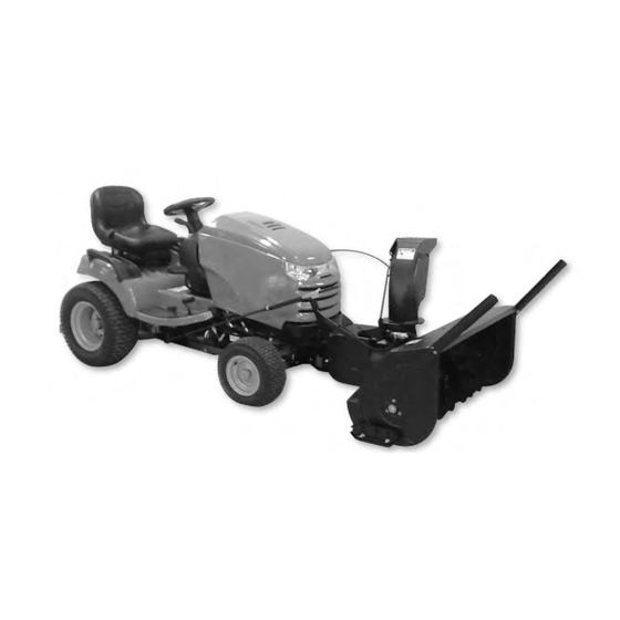
- Page 1 ATTACHMENT OPERATOR’S MANUAL 42” 2-Stage Snowthrower & Sub-frame Mfg. No. Description 1695360 42” 2-Stage Snowthrower 1695196 Sub-frame Hitch Briggs & Stratton Yard Power Products Group 1754620 Copyright © 2013 Briggs & Stratton Corporation Rev. H Milwaukee, WI USA. All Rights Reserved...
-
Page 3: Table Of Contents
Table of Contents Unpacking Recommendations ............. Hardware Bag / Hardware Contents ..........Operator Safety ................Assembly ..................Assemble Hitch ................. Assemble Push Bar Latch ............Bracket Installation ..............Install Lift Lever Kit ..............Belt Installation ................Install Lock Plate ............(Hydraulic Lift Models Only) ............. -
Page 4: Unpacking Recommendations
Please note the designated symbols for each kit when unpacking the contents. It is recommended that hardware for each kit is kept separate during the assembly process. 1695196 Sub-Frame Hitch 1695360 42” 2-Stage Snowthrower Hardware / Parts Identification Lower case letters identify pre-assembled and / or pre-existing hardware / parts. -
Page 5: Hardware Bag / Hardware Contents
Hardware Bag Contents A - CARRIAGE BOLT, H - CLEVIS PIN, I - HAIR PIN, J - HAIR PIN, 5/16”-16 x 1.0” (Qty. 4) .50” x 2.12” (Qty. 1) (Qty. 1) (Qty. 2) B - WASHER, C - LOCKWASHER, 5/16” (Qty. 4) .312”... - Page 6 Hardware Bag Contents / Hardware P - ZIP TIE, S - CARRIAGE BOLT, T - FLANGE NUT, Qty. 2) 5/16”-18 x 3/4” (Qty. 2) 5/16”-18 (Qty. 2) U -REFLECTORS, (Qty. 2) AA - SUPPORT CLAMP, BB - PUSH BAR ASSEMBLY, CC - HOOK ASSEMBLY, DD - PUSH BAR LATCH, EE - SPRING ANCHOR,...
- Page 7 Hardware Bag Contents / Hardware HH - LATCH ROD, II - HITCH ROD, Small, JJ - LIFT LEVER ASSEMBLY, KK - LIFT ROD ASSEMBLY, LL - DISCHARGE CHUTE ASSEMBLY, MM - DEFLECTOR CONTROL CABLE SUPPORT ARM, NN - SNOWTHROWER, OO - HITCH PIN, PP - SPRING ANCHOR, QQ - SPRING, RR - MOUNTING BRACKET ASSEMBLY,...
-
Page 8: Operator Safety
Operator Safety / SNOWTHROWERS This snowthrower is capable of amputating hands and feet and throwing objects. Failure to observe the following safety instructions could result in serious injury. Read these safety rules, and the safety rules in your tractor Operator’s Manual, and follow them closely. Failure to obey these rules could result in loss of control of vehicle, severe personal injury to yourself, or damage to property or equipment. -
Page 9: Safety Decals
Operator Safety / SNOWTHROWERS Recommended Accessories WARNING Tire chains are recommended when installing this Perform the Safety System Interlock test found in your attachment to your unit. tractor Operator’s Manual. If tractor does not pass the Safety Decals test, do not operate the tractor. See your authorized dealer. -
Page 10: Assembly
Assembly Assemble Push Bar Latch WARNING For 2012 Models & Previous Years Before beginning any service work turn off the PTO, set 1. Attach push bar latch (DD, Figure 2) onto each side of the parking brake, turn off the ignition, and disconnect sub-frame hitch (BB). -
Page 11: Bracket Installation
Assembly Bracket Installation For 2013 Models & Proceeding Years 4-Wheel Drive / Right Side For 2013 Models & Proceeding Years 1. Attached LEFT side of push bar (DD) to sub-frame hitch 2-Wheel Drive / Right Side (BB) as shown in Figure 2. 1. -
Page 12: Install Lock Plate (Hydraulic Lift Models Only)
Assembly Install Lock Plate - 3. Remove the hair pin (b, Figure 7) and pin (c) securing the spacer (d). Hydraulic Lift Models Only NOTE: If the lift bars are different, replace existing lift NOTE: Non-labeled parts in Figure 5 & 7 are pre-existing. bar with provided lift bar using existing hardware. -
Page 13: Install Rear Lift Rod
Assembly 2. Raise the rear of the hitch and place the hook assembly 5. Push the support clamp backwards until it is snug (CC, Figure 9) over the lift shaft between the welded against the hook assembly. Tighten the nuts on the washers. -
Page 14: Assemble Discharge Chute
Assembly 3. Secure lift rod assembly with safety clip (a, Figure 13). 3. Remove a chute retainer (d, Figure 15) and plastite Secure lift lever assembly with clevis pin (K) and safety screw (e), located on the reinforcement ring gear (f) of clip (L). -
Page 15: Attach Deflector Control Cable Support Arm
Assembly Install Snowthrower 5. Adjust the motor so that the chute gear (g, Figure 17) meshes with the discharge chute ring gear (h) and Connect to Hitch tighten the adjustment screws (i). 1. Position the snowthrower in front of the hitch. NOTE: Adjustment maybe required to allow chute to rotate lock to lock freely. -
Page 16: Install Chute Rotator Switch Non-Electric Height-Of-Cut Units
Assembly Install Chute Rotator Switch 4. Locate the tractor power leads (Figure 24), red with yellow stripe (c) and black (d), at the base of steering Non-Electric Height-of-Cut Units column. Connect these leads, color to color, to the switch wire harness (a). NOTE: Model year tractor’s 2012 and earlier with non- electric height of cut refer to service bulletin 2009-2 for proper chute electric component requirements. -
Page 17: Install Wire Harness To Chute Harness
Assembly Install Wire Harness to Chute Harness For 2013 Models & Proceeding Years (Electric Height-of-Cut Units) 1. Connect the switch wire harness (a, Figure 27) to the 1. Locate the electric height-of-cut harness (a, Figure 29) chute wire harness (N). Secure wire harness to tractor underneath tractor. -
Page 18: Install Spring Anchor
Assembly Install Spring Anchor 2. Remove capscrew (a, Figure 33) from spring anchor assembly. Insert capscrew through snowthrower For 2012 Models & Previous Years bracket (b) and screw into retainer and speed nut (c). 1. Open the tractor hood. Install the spring anchor (PP, 3. -
Page 19: Mount Remote Deflector Control
Assembly Mount Remote Deflector Control Rear Lift Rod Alteration 1. Using the template (a, Figure 35) included in the back Units with Suspension of this manual, drill two 9/32” holes in the left side of the On units with suspension, adjustment handle (a, Figure 36) dashboard to mount the remote chute control. -
Page 20: Install Drive Belt
Assembly Install Drive Belt 3. With the snowthrower drive belt installed, the trunnion (a, Figure 41) should be between the marks (b) on 1. Route the drive belt (TT) as shown in Figure 40. The spring tension bracket for correct belt tension. Turn back of the belt rides in the back-side idlers (2 &... -
Page 21: Required Accessories
Required Accessories Required Accessories Recommended Accessories - It is required that tire chains and two rear wheel weights A rear-mounted weight box can also be added for or Quick Tach Weights are used. additional traction. The maximum weight added to the tractor should not exceed 35 lbs. -
Page 22: Features & Controls
Features & Controls Control Functions A. Electric Spout Rotator Switch Controls the electric spout rotator. The information below briefly describes the function of individual controls. Operating the tractor and attachment B. PTO Switch requires the combined use of these controls and additional Engages and disengages the PTO to start and stop the controls whose operation is described in the tractor snowthrower. -
Page 23: Operation
Operations WARNING WARNING If auger does not start and stop when engaging/ Perform the Safety System Interlock test found in your disengaging electric clutch, see your authorized dealer. tractor Operator’s Manual. If tractor does not pass the Under no circumstances should you attempt to defeat test, do not operate the tractor. -
Page 24: Snow Removal Suggestions
Operation Snow Removal Suggestions Daily Storage • Determine the best snow removal pattern before 1. Run the snowthrower a few minutes after blowing snow beginning. to prevent freeze-up of auger. • Wind direction is an important factor to consider. Rotate 2. -
Page 25: Lift Variations When Using Attachments
Operation Lift Variations When Using Attachments Hydraulic Lift Models When a front-mounted attachment such as a snowthrower or dozer blade is used with the tractor, the lift mechanism must be locked to provide downward force. When the Snowthrower & mower is reinstalled the downward pressure lock must be Dozer Applications released so that the mower can float. -
Page 26: Maintenance
Maintenance Check Auger Gearbox Oil Level WARNING Perform this check every season. To avoid serious injury, perform maintenance on the 1. Remove the plug (a, Figure 46) from the side of the unit only when the engine is stopped and all moving auger gearbox. -
Page 27: Troubleshooting
Troubleshooting Troubleshooting Chart WARNING While normal care and regular maintenance will extend To avoid serious injury, perform maintenance on the the life of your equipment, prolonged or constant use may tractor or mower only when the engine is stopped and eventually require that service be performed to allow it to the parking brake engaged. -
Page 28: Skid Shoe Adjustment
Troubleshooting Auger Shear Pins Skid Shoe Adjustment The auger shear pins (a, Figure 50) are designed to break On smooth surfaces such as concrete or asphalt, the if the auger strikes an object. Replace the shear pins with scraper bar should scrape the surface. On surfaces such original factory specification shear pins ONLY. -
Page 29: Lift Assist Adjustment
Troubleshooting 3. If trunnion cannot be placed between marks, loosen capscrew (d) and reposition idler pulley (e) as necessary. The pivot bracket (f) should be perpendicular to the hitch. Retighten capscrew (d) and repeat step 2. Figure51 IMPORTANT NOTE DO NOT OVER-COMPRESS THE SPRING. In addition to providing downward pressure, the spring is an elastic medium that absorbs shocks caused by bumps and cracks in ground surfaces. -
Page 30: Template
Template Line Template Up with Top Crease of Plastic Dashboard Mark and Drill One 9/32” Hole Line Template Up with Top Crease of Plastic Dashboard LG 1-Stage Snow w/TEMPL.epsf... -
Page 31: Warranty
Warranty BRIGGS & STRATTON PRODUCTS WARRANTY POLICY APRIL 2012 LIMITED WARRANTY Briggs & Stratton warrants that, during the warranty period specified below, it will repair or replace, free of charge, any part that is defective in material or workmanship or both. Transportation charges on product submitted for repair or replacement under this warranty must be borne by purchaser.
Need help?
Do you have a question about the 1695360 and is the answer not in the manual?
Questions and answers