Sign In
Upload
Manuals
Brands
Elektro-Automatik Manuals
Power Supply
PSI 9000 DT Series
Elektro-Automatik PSI 9000 DT Series Manuals
Manuals and User Guides for Elektro-Automatik PSI 9000 DT Series. We have
3
Elektro-Automatik PSI 9000 DT Series manuals available for free PDF download: Operating Manual
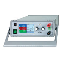
Elektro-Automatik PSI 9000 DT Series Operating Manual (162 pages)
DC Laboratory Power Supply
Brand:
Elektro-Automatik
| Category:
Power Supply
| Size: 3 MB
Table of Contents
Deutsch
3
Table of Contents
3
Zu diesem Dokument
5
Aufbewahrung und Verwendung
5
Urheberschutz (Copyright)
5
Geltungsbereich
5
Symbolerläuterungen
5
Gewährleistung und Garantie
5
Haftungsbeschränkungen
5
Entsorgung des Gerätes
6
Produktschlüssel
6
Bestimmungsgemäße Verwendung
6
Sicherheit
7
Sicherheitshinweise
7
Verantwortung des Bedieners
8
Pflichten des Betreibers
8
Anforderungen an das Bedienpersonal
8
Alarmsignale
9
Technische Daten
9
Zulässige Betriebsbedingungen
9
Allgemeine Technische Daten
9
Spezifische Technische Daten
10
Ansichten
22
Bedienelemente
25
Aufbau und Funktion
26
Allgemeine Beschreibung
26
Blockdiagramm
26
Lieferumfang
27
Optionales Zubehör
27
Die Bedieneinheit (HMI)
28
USB-Port (Rückseite)
31
Ethernetport
31
Analogschnittstelle
31
Sense-Anschluß (Fernfühlung)
31
Installation & Inbetriebnahme
32
Aufstellung des Gerätes
32
Auspacken und Sichtkontrolle
32
Installation
32
Lagerung
32
Sicherheitsmaßnahmen vor Installation und Gebrauch
32
Verpackung
32
Vorbereitung
32
Anschließen an das Stromnetz (AC)
37
Anschließen von DC-Lasten
37
Anschließen der Analogen Schnittstelle
38
Anschließen der Fernfühlung
38
Erdung des DC-Ausgangs
38
Anschließen des USB-Ports (Rückseite)
39
Erneute Inbetriebnahme nach Firmwareupdates Bzw. Längerer Nichtbenutzung
39
Erstinbetriebnahme
39
Bedienung und Verwendung
40
Personenschutz
40
Regelungsarten
40
Spannungsregelung / Konstantspannung
40
Innenwiderstandsregelung
41
Leistungsregelung / Konstantleistung / Leistungsbegrenzung
41
Stromregelung / Konstantstrom / Strombegrenzung
41
Alarmzustände
42
Power Fail
42
Überleistung (Overpower)
42
Überspannung (Overvoltage)
42
Überstrom (Overcurrent)
42
Übertemperatur (Overtemperature)
42
Ausschalten des Gerätes
43
Einschalten des Gerätes
43
Konfiguration IM Menu
43
Manuelle Bedienung
43
Betriebsart Wechseln
50
Einstellgrenzen (Limits)
50
Sollwerte Manuell Einstellen
51
Ansichtsmodus der Hauptanzeige Wechseln
52
Die Meßleisten
52
Datenaufzeichnung auf USB-Stick (Logging)
53
DC-Ausgang Ein- oder Ausschalten
53
Allgemeines
55
Bedienorte
55
Fernsteuerung
55
Fernsteuerung über eine Digitale Schnittstelle
55
Fernsteuerung über Analogschnittstelle (AS)
56
Alarme und Überwachung
60
Begriffsdefinition
60
Gerätealarme und Events Handhaben
60
Bedieneinheit (HMI) Sperren
62
Einstellgrenzen (Limits) Sperren
63
Nutzerprofile Laden Und Speichern
63
Allgemeines
64
Der Funktionsgenerator
64
Einleitung
64
Arbeitsweise
65
Manuelle Bedienung
65
Dreieck-Funktion
66
Sinus-Funktion
66
Rechteck-Funktion
67
DIN 40839-Funktion
68
Trapez-Funktion
68
3.10.10 Arbiträr-Funktion
69
3.10.11 Rampen-Funktion
73
3.10.12 Fernsteuerung des Funktionsgenerators
73
Betrieb als Batterielader
74
Instandhaltung & Wartung
75
Parallelschaltung
74
Reihenschaltung
74
Weitere Anwendungen
74
Aktualisierung der Firmwares
75
Defekte Netzsicherung Tauschen
75
Fehlersuche / Fehlerdiagnose / Reparatur
75
Wartung / Reinigung
75
Abgleichvorgang
76
Einleitung
76
Nachjustierung (Kalibrierung)
76
Vorbereitung
76
Ersatzableitstrommessung nach DIN VDE 0701-1
78
Service & Support
79
Kontaktmöglichkeiten
79
English
85
General
87
Reparaturen
79
About this Document
87
Copyright
87
Limitation of Liability
87
Retention and Use
87
Symbols and Warnings
87
Validity
87
Warranty
87
Disposal of Equipment
88
Intended Usage
88
Product Key
88
Responsibility of the User
89
Safety
89
Safety Notices
89
Responsibility of the Operator
90
User Requirements
90
Alarm Signals
91
Approved Operating Conditions
91
General Technical Data
91
Technical Data
91
Specific Technical Data
92
Views
104
Control Elements
107
Block Diagram
108
Construction and Function
108
General Description
108
Optional Accessories
109
Scope of Delivery
109
The Control Panel (HMI)
110
Analog Interface
113
Ethernet Port
113
Sense Connector (Remote Sensing)
113
Installation & Commissioning
114
USB Port (Rear Side)
113
Installation
114
Installing the Device
114
Packaging
114
Preparation
114
Safety Procedures before Installation and Use
114
Storage
114
Unpacking and Visual Check
114
Connection to AC Supply
119
Connection to DC Loads
119
Connecting the Analog Interface
120
Connection of Remote Sensing
120
Grounding of the DC Output
120
Commission after a Firmware Update or a Long Period of Non-Use
121
Connecting the USB Port (Rear Side)
121
Initial Commission
121
Operating Modes
122
Operation and Application
122
Personal Safety
122
Voltage Regulation / Constant Voltage
122
Current Regulation / Constant Current / Current Limiting
123
Internal Resistance Regulation
123
Power Regulation / Constant Power / Power Limiting
123
Alarm Conditions
124
Overcurrent Protection
124
Overpower Protection
124
Overtemperature
124
Overvoltage Protection
124
Power Fail
124
Configuration Via MENU
125
Manual Operation
125
Switching off the Device
125
Switching on the Device
125
Adjustment Limits (Limits)
132
Changing the Operating Mode
132
Manual Adjustment of Set Values
133
Switching the Main Screen View
133
Switching the DC Output on or off
134
The Meter Bars
134
Recording to USB Stick (Logging)
135
Control Locations
136
General
136
Remote Control
136
Remote Control Via a Digital Interface
136
Remote Control Via the Analog Interface (AI)
137
Alarms and Monitoring
141
Definition of Terms
141
Device Alarm and Event Handling
141
Control Panel (HMI) Lock
143
Limits Lock
144
Loading and Saving a User Profile
144
General
146
Introduction
146
The Function Generator
146
Method of Operation
147
Manual Operation
147
Sine Wave Function
148
Rectangular Function
149
Triangular Function
149
DIN 40839 Function
150
Trapezoidal Function
150
3.10.10 Arbitrary Function
151
3.10.11 Ramp Function
155
3.10.12 Remote Control of the Function Generator
155
Operation as Battery Charger
156
Service and Maintenance
157
Other Applications
156
Parallel Operation
156
Series Connection
156
Fault Finding / Diagnosis / Repair
157
Firmware Updates
157
Maintenance / Cleaning
157
Replacing a Defect Mains Fuse
157
Calibration
158
Calibration Procedure
158
Contact and Support
160
Preface
158
Preparation
158
Contact Options
160
General
160
Advertisement
Elektro-Automatik PSI 9000 DT Series Operating Manual (80 pages)
DC Laboratory Power Supply
Brand:
Elektro-Automatik
| Category:
Power Supply
| Size: 2 MB
Table of Contents
Operating Guide
1
Table of Contents
3
General
5
About this Document
5
Copyright
5
Limitation of Liability
5
Retention and Use
5
Symbols and Warnings
5
Validity
5
Warranty
5
Disposal of Equipment
6
Intended Usage
6
Product Key
6
Responsibility of the User
7
Safety
7
Safety Notices
7
Responsibility of the Operator
8
User Requirements
8
Alarm Signals
9
Approved Operating Conditions
9
General Technical Data
9
Technical Data
9
Specific Technical Data
10
Views
22
Block Diagram
26
Construction and Function
26
General Description
26
Optional Accessories
27
Scope of Delivery
27
The Control Panel (HMI)
28
Analog Interface
31
Ethernet Port
31
Sense Connector (Remote Sensing)
31
Installation & Commissioning
32
USB Port (Rear Side)
31
Installation
32
Installing the Device
32
Packaging
32
Preparation
32
Safety Procedures before Installation and Use
32
Storage
32
Unpacking and Visual Check
32
Connection to AC Supply
37
Connection to DC Loads
37
Connecting the Analog Interface
38
Connection of Remote Sensing
38
Grounding of the DC Output
38
Commission after a Firmware Update or a Long Period of Non-Use
39
Connecting the USB Port (Rear Side)
39
Initial Commission
39
Operating Modes
40
Operation and Application
40
Personal Safety
40
Voltage Regulation / Constant Voltage
40
Current Regulation / Constant Current / Current Limiting
41
Internal Resistance Regulation
41
Power Regulation / Constant Power / Power Limiting
41
Alarm Conditions
42
Overcurrent Protection
42
Overpower Protection
42
Overtemperature
42
Overvoltage Protection
42
Power Fail
42
Configuration Via Menu
43
Manual Operation
43
Switching off the Device
43
Switching on the Device
43
Adjustment Limits (Limits)
50
Changing the Operating Mode
50
Manual Adjustment of Set Values
51
Switching the Main Screen View
52
The Meter Bars
52
Switching the DC Output on or off
53
Control Locations
54
General
54
Remote Control
54
Remote Control Via a Digital Interface
54
Remote Control Via the Analog Interface (AI)
55
Alarms and Monitoring
59
Definition Of Terms
59
Device Alarm and Event Handling
59
Control Panel (HMI) Lock
61
Loading And Saving A User Profile
62
General
63
Introduction
63
The Function Generator
63
Manual Operation
64
Method of Operation
64
Sine Wave Function
65
Rectangular Function
66
Triangular Function
66
DIN 40839 Function
67
Trapezoidal Function
67
Arbitrary Function
68
Ramp Function
72
Remote Control of the Function Generator
72
Operation as Battery Charger
73
Service and Maintenance
74
Other Applications
73
Series Connection
73
Parallel Operation
73
Fault Finding / Diagnosis / Repair
74
Firmware Updates
74
Maintenance / Cleaning
74
Replacing a Defect Mains Fuse
74
Calibration
75
Calibration Procedure
75
Contact and Support
77
Preface
75
Preparation
75
Contact Options
77
General
77
Elektro-Automatik PSI 9000 DT Series Operating Manual (76 pages)
DC Laboratory power supply
Brand:
Elektro-Automatik
| Category:
Power Supply
| Size: 2 MB
Table of Contents
Operating Guide
1
Table of Contents
3
About this Document
5
Retention and Use
5
Copyright
5
Validity
5
Symbols and Warnings
5
Warranty
5
Limitation of Liability
5
Disposal of Equipment
6
Product Key
6
Intended Usage
6
Safety
7
Safety Notices
7
Responsibility of the User
8
Responsibility of the Operator
8
User Requirements
8
Alarm Signals
9
Technical Data
9
Approved Operating Conditions
9
General Technical Data
9
Specific Technical Data
10
Views
22
Control Elements
25
Construction and Function
26
General Description
26
Block Diagram
26
Scope of Delivery
26
Optional Accessories
26
The Control Panel (HMI)
27
USB Port (Rear Side)
30
Ethernet Port
30
Analog Interface
30
Sense Connector (Remote Sensing)
30
Installation & Commissioning
31
Storage
31
Packaging
31
Unpacking and Visual Check
31
Safety Procedures before Installation and Use
31
Preparation
31
Installing the Device
31
Connection to AC Supply
36
Connection to DC Loads
36
Grounding of the DC Output
37
Connection of Remote Sensing
37
Connecting the Analog Interface
37
Connecting the USB Port (Rear Side)
38
Initial Commission
38
Commission after a Firmware Update or a Long Period of Non-Use
38
Operation and Application
39
Personal Safety
39
Operating Modes
39
Voltage Regulation / Constant Voltage
39
Current Regulation / Constant Current / Current Limiting
40
Power Regulation / Constant Power / Power Limiting
40
Internal Resistance Regulation
40
Alarm Conditions
41
Power Fail
41
Overtemperature
41
Overvoltage Protection
41
Overcurrent Protection
41
Overpower Protection
41
Manual Operation
42
Switching the Device on
42
Switching the Device off
42
Configuration Via MENU
42
Adjustment Limits (Limits)
47
Changing the Operating Mode
47
Manual Adjustment of Set Values
48
Switching the Main Screen View
49
The Meter Bars
49
Switching the DC Output on or off
50
Recording to USB Stick (Logging)
50
Remote Control
52
General
52
Control Locations
52
Remote Control Via a Digital Interface
52
Remote Control Via the Analog Interface (AI)
53
Alarms and Monitoring
57
Definition of Terms
57
Device Alarm and Event Handling
57
Control Panel (HMI) Lock
59
Limits Lock
60
Loading and Saving an User Profile
60
The Function Generator
61
Introduction
61
General
61
Method of Operation
62
Manual Operation
62
Sine Wave Function
63
Triangular Function
64
Rectangular Function
64
Trapezoidal Function
65
DIN 40839 Function
65
Arbitrary Function
66
Ramp Function
70
Remote Control of the Function Generator
70
Other Applications
71
Series Connection
71
Parallel Operation
71
Operation as Battery Charger
71
Maintenance / Cleaning
72
Calibration
73
Advertisement
Advertisement
Related Products
Elektro-Automatik PSI 900 3u
Elektro-Automatik PSI 9000 WR 3U SLAVE
Elektro-Automatik PSI 9000 3U Series
Elektro-Automatik PSI 9000 2U Series
Elektro-Automatik PSI 9000 15U Series
Elektro-Automatik PSI 9000 24U Series
Elektro-Automatik PSI 9000 15U
Elektro-Automatik PSI 9000 24U
Elektro-Automatik PSI 9000 T
Elektro-Automatik PSI 9000
Elektro-Automatik Categories
Power Supply
UPS
Enclosure
Test Equipment
Racks & Stands
More Elektro-Automatik Manuals
Login
Sign In
OR
Sign in with Facebook
Sign in with Google
Upload manual
Upload from disk
Upload from URL