Table of Contents
Advertisement
Advertisement
Table of Contents

Related Manuals for Chauvin Arnoux C.A 6416


Summary of Contents for Chauvin Arnoux C.A 6416
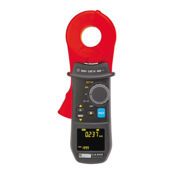
- Page 1 GROUND TESTER C.A 6416 C.A 6417 User’s manual E N G L I S H...
- Page 2 Thank you for purchasing a C.A 6416 or C.A 6417 ground tester. For best results from your instrument: ■ read these operating instructions carefully, ■ comply with the precautions for use. Symbol Meaning WARNING, risk of DANGER! The operator must refer to these instructions whenever this danger symbol appears.
- Page 3 PRECAUTIONS FOR USE This instrument and its accessories comply with safety standards EN 61010-1, EN 61010-030, and EN 61010-2-032 for voltages of 600V in category IV at an altitude of less than 2000m, indoors, with a degree of pollution of not more than 2. Failure to observe the safety instructions may result in electric shock, fire, explosion, and destruction of the instrument and of the installations.
- Page 4 CONTENTS Page 1. GETTING STARTED ..................7 1.1 UNPACKING ....................7 1.2 INSERTING THE BATTERIES ..............7 1.3 Setting the date and time ................7 1.4 EXAMPLE OF DISPLAY ................8 2. DESCRIPTION OF THE DEVICE ..............8 2.1 FUNCTIONS OF THE DEVICE ..............9 2.2 FRONT PANEL ..................
- Page 5 5.2 USE IN ADVANCED MODE ............... 24 5.2.1 OBJECT .................... 24 5.2.2 SELECTION ..................24 5.2.3 PARAMETERIZING THE MEASUREMENT ........24 5.2.4 MEASUREMENT ................25 5.2.5 MEASUREMENT RESULT ............... 25 5.3 COMPLEMENTARY INFORMATION ............26 5.3.1 PRODUCT ZXI GREATER THAN 50V ..........26 5.3.2 IMPEDANCE GREATER THAN 1500Ω...
- Page 6 10.1 REFERENCE CONDITIONS ..............44 10.2 ELECTRICAL CHARACTERISTICS ............44 10.2.1 LOOP RESISTANCE MEASUREMENT ........... 44 10.2.2 LOOP INDUCTANCE MEASUREMENT ........... 45 10.2.3 ESTIMATE OF THE CONTACT VOLTAGE ........45 10.2.4 CURRENT MEASUREMENT ............45 10.3 VARIATIONS IN THE DOMAIN OF USE ..........46 10.4 POWER SUPPLY ..................
-
Page 7: Getting Started
1. G E T T ING S TAR T E D UNPACKING Rep. Designation Carrying case. C.A. 6416 or C.A. 6417 earth clamp. Set of 4 AA batteries (1.5V). CD containing the GTC application and the operating instructions. Verification certificate. Safety data sheet (20 languages) Quick Start guide Fig. -
Page 8: Example Of Display
EXAMPLE OF DISPLAY figure opposite shows display, upon first use, with the device set to Ω+A. The measured current 30.0mA impedance is 7.9Ω. The buzzer is active and the memory is empty. Note: This display corresponds to Standard mode. Advanced mode, additional screens are available;... -
Page 9: Functions Of The Device
FUNCTIONS OF THE DEVICE ■ Easy-to-use device intended for measurement of the loop impedance in a parallel earth network, by a simpler method than the traditional method with 2 auxiliary rods. Loop ohmmeter: measurement of loop impedances from 0.01Ω to 1,500Ω. The ohmmeter function makes allowance for the presence of inductances in the loop, making impedance measurements more accurate at low values. -
Page 10: Front Panel
FRONT PANEL Measurement head Trigger Guard Rotary switch used to select a measurement Display backlight key function, SET-UP, or memory read MEM key, to store HOLD key, to freeze measurements the display OLED display unit ► key, for validation and browsing in the measurement screens Fig. - Page 11 Rep. Designation See § Measurement head. Guard. The user's hand must be below this zone and not touch the measurement head (item 1). Function switch. OFF: device off. Ω+A: simultaneous selection of the Loop impedance measurement and the Leakage current measurement. A: selection of the Current measurement.
-
Page 12: Device–Rear Panel
Rep. Designation See § ► Function that depends on the setting of the function switch, as follows: When the device is set to Ω+A (Advanced Mode) 5.2.5 Short press: switches the display through the following 3 modes, in order: ■ Display of the impedance recalculated at the selected frequency. -
Page 13: Display Unit
DISPLAY UNIT Fig. 6 Rep. Designation See § ■ Display of the buzzer active state; the icon is masked when the buzzer is inactive. ■ Selection of the buzzer operating mode via SET-UP menu 2. Indicator of freezing of the measurement display when the HOLD key is pressed or in the Pre-Hold mode Indicates that the main display shows the date (with the function switch set to MR or SET-UP). - Page 14 Units of the central measurements display unit: ■ V: contact voltage measurement unit. ■ Ω: impedance measurement unit. Symbol used for impedances at the measurement frequency, for impedances referred to the network frequency, or for the resistive component. Unit of the alarm displayed. The alarm can be defined on an impedance, a voltage, or a current, depending on the measurement chosen (Ω+A or A).
-
Page 15: Audible Signals
AUDIBLE SIGNALS The device can generate audible signals of four types: Type Duration Meaning sound Low-pitched Short Normal use (key pressed). Permanent Over(under-)shoot of a measurement alarm threshold (Ω, A). High-pitched Short Abnormal use (for example, memory full). Permanent Overshoot of a safety alarm threshold (V). The audible signal can be activated or deactivated in SET-UP (see chapter 8, menu 2). -
Page 16: Measurement Principle
3. ME AS UR E ME NT P R INC IP L E The schematic diagram below illustrates the general case of measurement of the resistance of a loop comprising: ■ The earth electrode Rx; ■ The earth; ■ Several earth electrodes of resistance R ■... -
Page 17: Inserting The Batteries
4. US E INSERTING THE BATTERIES Refer to §11.2. COMMISSIONING THE DEVICE With the clamp closed and not clamping any conductor, set the function switch to a position other than OFF. All icons of the display unit light for approximately 2 seconds, before possible entry of the date and time (see next section). -
Page 18: Standard Or Advanced Mode
STANDARD OR ADVANCED MODE The earth clamp can be used in two ways. ■ The Standard mode makes the standard loop ohmmeter clamp measurements. ■ The Advanced mode is used to refine and complete the measurements: Impedance referred to the selected frequency. Contact voltage. -
Page 19: Storage Of The Data
4.8.4 MEMORY FULL When 300 values have been stored and the memory is full (model C.A 6416), the sequence number is replaced by FULL. The next time the MEM, key is pressed, a disablement beep is emitted and the FULL indication blinks. Storage is rejected; it is then necessary to erase the whole memory before recording again. -
Page 20: Reading The Stored Data
FULL. The next time the MEM key is pressed, a disablement beep is emitted and the FULL indication blinks. 4.8.5 READING THE STORED DATA The data can be looked up using the MR function. See chapter 7. MANAGEMENT OF THE ALARMS The device has 3 distinct alarms that can be parameterized. -
Page 21: Current Alarm
4.9.3 CURRENT ALARM If the current exceeds the threshold set, the alarm symbol and the alarm threshold are displayed and blink. If the buzzer is active, a low-pitched audible signal is emitted. Fig. 10 4.9.4 IMPEDANCE ALARM If there is no voltage alarm, no detection of NOISE, and no current alarm, an alarm on the impedance may be triggered. - Page 22 4.9.4.2 High threshold configuration An audible signal is emitted at values exceeding the threshold (detection of an earthing impedance that is too high). Fig. 12 If the impedance crosses the selected threshold, a low-pitched audible signal is emitted. 4.9.4.3 Priority of the alarms If several alarms are triggered simultaneously, a priority rule determines the display and the corresponding sound: ■...
-
Page 23: Ω+A Position
5. Ω+A P OS IT ION Since the measurement frequency is audible, the operator hears a discontinuous audible signal (beep-beep). This is neither an operating fault nor an alarm, and it cannot be eliminated. This audible signal is amplified by the presence of current in the loop. -
Page 24: Measurement Result
5.1.4 MEASUREMENT RESULT Once the measurement has stabilized, the display unit indicates: ■ The leakage current. ■ The impedance of the loop at the frequency of 2083Hz. The impedance is measured only if the leakage current is less than 10A. In the 10A–40A range, only the current is displayed;... -
Page 25: Measurement
5.2.4 MEASUREMENT ■ Place the conducting wire of the circuit to be measured in the clamp and close the clamp. If the clamp is incorrectly closed, the icon is displayed. ■ If necessary, use the HOLD key to freeze the measurement. See §4.6. ■... -
Page 26: Complementary Information
Third screen Press ► to display the 3rd screen, which indicates the values of R and L. ■ The loop inductance and loop resistance are displayed. Fig. 16 ■ When the inductive component is negligible (*) with respect to the resistive component, the symbol R=Z is displayed, and only the impedance... -
Page 27: Impedance Greater Than 1500Ω
5.3.2 IMPEDANCE GREATER THAN 1500Ω In this case: ■ The impedance display indicates O.R (Over range). Fig. 19 5.3.3 PERTURBING LEAKAGE CURRENT If the current is greater than 5A, or if it is significantly deformed: ■ The blinking Noise symbol displayed. -
Page 28: Storage Of The Measurements
If the current is greater than 40A, the current display indicates O.R (Over Range). Fig. 22 5.3.5 STORAGE OF THE MEASUREMENTS Refer to § 4.8.2. 5.3.6 PRESENCE OF ALARMS Refer to §4.9. -
Page 29: Position A
6. P OS IT ION A OBJECT In this mode, the clamp measures the electric current, independently of any earth measurement. PARAMETERIZING THE MEASUREMENT If necessary, first adjust the current alarm threshold in accordance with §8.5, menu 6. MEASUREMENT ■ Place the conducting wire of the circuit in which the current is to be measured, in the clamp and close the clamp. -
Page 30: Management Of The Alarms
MANAGEMENT OF THE ALARMS preset alarm threshold exceeded, reminder threshold and the value of the current measured blink Refer to §4.9. Fig. 24... -
Page 31: Memory Read (Mr)
7. ME MOR Y R E AD (MR ) OBJECT The MR position (Memory Read, display of stored data) is used to display measurements previously stored by pressing the MEM key. SELECTION OF THE MEMORY READ MODE Set the function switch to MR. The choice of mode (Standard or Advanced) was made by parameterizing;... -
Page 32: Data Displayed In Advanced Mode
Press ► display measurement storage date-time screen. To exit from the memory read mode, set the rotary switch to the desired mode. Fig. 27 7.3.2 DATA DISPLAYED IN ADVANCED MODE icon indicates use of the Advanced mode; the user then disposes of 4 distinct screens. -
Page 33: Use Of The Keys
Screen no. 3 The figure opposite illustrates a resistance impedance measurement (switch set to Ω+A). Press ► to display the next screen. Fig. 30 Screen no. 4 The figure opposite illustrates the date and time of the measurement (switch set to Ω+A), namely: ■... -
Page 34: Exiting From The Read Mode
7.3.5 EXITING FROM THE READ MODE Set the function switch to the desired measurement position (OFF, Ω+A, A or SET-UP). 7.3.6 EXPORTING DATA TO A PC The model C.A. 6417 has a communication capability that can be used to transfer all or some of the recorded measurements to GTC software for PC. - Page 35 Refer to the on-line help of the software for a description of its operation. Setup is accessed to configure the elements accessible in the clamp setup. It also serves to personalize the name of the Bluetooth peripheral when the user has several earth clamps.
-
Page 36: Set-Up
8. S E T-UP OBJECT The SET-UP position gives access to the following menus: Function Erasure of the memory. Activation/Deactivation of the buzzer. Activation/Deactivation of automatic switching off. Setting of the impedance alarm threshold (Ω). Setting of the voltage alarm threshold (V). Setting of the current alarm threshold (I). -
Page 37: Selecting A Specific Menu
SELECTING A SPECIFIC MENU Use the keys as follows. Action ▲ Move up in the menu tree. ▼ Move down in the menu tree. ► Select the menu displayed or return to the previous menu. When changes have been made in one of the SET-UP menus (other than deletion), the changes can be cancelled by turning the function switch to a position other than SET-UP, provided that there has not been a return to the main menu (press on ►). - Page 38 Menu no. Indication Object and use Setting the impedance alarm threshold (Ω) AL. Ω Enter the menu by ►. AL. Ω blinks. ■ Setting the sense of the alarm Press ▲ or ▼ to select the state of the alarm: ■...
- Page 39 Menu no. Indication Object and use Setting the current alarm threshold (I) AL. A Enter the menu by ►. AL. A blinks. ■ Activation/Deactivation of the alarm Press ▲ or ▼ to select the state of the alarm (Fig. ■ 6, item 13): : deactivated.
- Page 40 Menu no. Indication Object and use Selecting the Standard or Advanced operating mode Enter the menu by ►. USE blinks. ■ Press ▲ or ▼ to select the Standard or Advanced ■ mode. - Advanced mode: the icon is displayed. - Standard mode: Std is displayed.
- Page 41 Menu no. Indication Object and use Activating the adjustment menus This function gives access to the following 3 sub- functions: ■ CAL R: adjustment of the impedance measurement. See menu 13. ■ CAL I: adjustment of the current measurement. See menu 14.
- Page 42 Current measurement adjustment procedure CAL. Additional equipment necessary ■ A source of stabilized 0.1 and 10A current. Adjustment of the current measurement ■ Press ► for 3 seconds to validate CAL. I function The sensitivity of the channels used in the current measurement will be recalculated on 2 current values.
-
Page 43: Off Position
9. OF F P OS IT ION The device can be switched off manually or automatically. MANUAL SWITCHING OFF Set the function switch to OFF. AUTOMATIC SWITCHING OFF The automatic switching off function acts after 5 minutes of inactivity, meaning no key pressed, no change of switch setting, and no opening of the clamp. -
Page 44: Technical Characteristics
10. T E C HNIC AL C HAR AC T E R IS T IC S 10.1 REFERENCE CONDITIONS Quantities of influence Reference conditions Ambient temperature 23±3°C. Relative humidity 50%RH±10%. Battery voltage 6V±0.2V. Magnetic field < 40A/m DC. No AC field. Electric field <... -
Page 45: Loop Inductance Measurement
Measurement frequency: 2083Hz. Transposition frequency: choice of 50, 60, 128, or 2083Hz for the impedance calculation. Maximum overloads: - permanent current 100A maximum (50/60Hz). - transient current (<5s) 200A (50/60Hz). 10.2.2 LOOP INDUCTANCE MEASUREMENT Measurement ranges (µH) Resolution (µH) Intrinsic uncertainty 10 to 100 ±5% ±R 100 to 500... -
Page 46: Variations In The Domain Of Use
10.3 VARIATIONS IN THE DOMAIN OF USE The influence is characterized by an Accuracy class number for each quantity of influence. Influence Quantity of Limit of the Quantities Typical influence Domain influenced Temperature -20° c to +55° c A, Ω , Uc 1 ct/10°C 2 ct/10°C... -
Page 47: Environmental Conditions
10.5 ENVIRONMENTAL CONDITIONS Fig. 33 1. Domain of reference (CEI160). 2. Domain of operation. 3. Domain of storage (without batteries). According to CEI359 category II (equipment for indoor and outdoor use). 10.6 MECHANICAL CHARACTERISTICS Dimensions: 55x95x262mm (thickness, width, height). Max. clamping diameter: 35mm. Opening: 35mm. -
Page 48: Servicing And Maintenance
11. S E R V IC ING AND MAINT E NANC E Except for the batteries, the instrument contains no parts likely to be replaced by personnel who are not specially trained and accredited. Any unauthorized repair or replacement of a part by an “equivalent” may gravely impair safety. -
Page 49: Preservation Of Stored Data
11.2.2 PRESERVATION OF STORED DATA When the batteries are removed, the data (recorded measurement values, alarm thresholds) are preserved. The date and time must be reset if the batteries are out for more than 2 minutes. 11.3 CHECK OF ACCURACY 11.3.1 OBJECT AND EQUIPMENT NECESSARY Regular checking serves to verify the accuracy of the clamp and thereby detect... -
Page 50: Procedure
This instrument should be checked at least once a year. For checking and calibration, contact one of our accredited metrology laboratories (information and contact details available on request), at our Chauvin Arnoux subsidiary or the branch in your country. 11.6 REPAIR For all repairs before or after expiry of warranty, please return the device to your distributor. -
Page 51: To Order
13. TO OR DE R C.A. 6416 EARTH CLAMP ............P01122015 Supplied in a carrying case with: - 4 LR6 or AA alkaline batteries - a test report - a CD ROM containing the software with a simplified GTC driver and user manual (one per language) - a multilingual quick start guide - a multilingual safety data sheet... - Page 52 Tel: 01 61 61 9 61-0 - Fax: 01 61 61 9 61-61 Tel: (01) 890 425 - Fax: (01) 890 424 SCANDINAVIA - CA Mätsystem AB USA - Chauvin Arnoux Inc - d.b.a AEMC Instruments 200 Foxborough Blvd. - Foxborough - MA 02035 Tel: +1 Sjöflygvägen 35 - SE 18304 TÄBY ...
Need help?
Do you have a question about the C.A 6416 and is the answer not in the manual?
Questions and answers