Table of Contents
Advertisement
Advertisement
Table of Contents

Related Manuals for Chauvin Arnoux C.A 6030


Summary of Contents for Chauvin Arnoux C.A 6030
- Page 1 GB - User’s manual C.A 6030 Loop and residual current device tester...
- Page 2 Thank you for purchasing a C.A 6030 loop and RCD tester. For best results from your instrument: „ read these operating instructions carefully, „ comply with the precautions for use. WARNING, risk of DANGER! The operator must refer to these instructions whenever this danger symbol appears.
-
Page 3: Table Of Contents
CONTENTS 1. FIRST START-UP ..................................4 1.1. Unpacking ..................................4 1.2. Accessories ..................................4 1.3. Replacement parts ................................. 4 1.4. Inserting the batteries ..............................5 2. PRESENTATION ..................................6 2.1. Device ..................................... 6 2.2. Functions of the device ..............................7 2.3. -
Page 4: First Start-Up
1. FIRST START-UP 1.1. UNPACKING Œ ‘ Ž FICHE DE SÉCURITÉ DU C.A 6116 (FR) Vous venez d’acquérir un contrôleur d’installation C.A 6116 et nous vous remercions de votre confiance. Pour obtenir le meilleur service de votre appareil : ... -
Page 5: Inserting The Batteries
1.4. INSERTING THE BATTERIES Turn the device over. Use a coin to unscrew the quarter-turn screw of the battery compartment cover. Raise the prop and pull on it to withdraw the Insert the six batteries in the compartment (three battery compartment cover. to the right and three to the left), observing the indicated polarity (+ up). -
Page 6: Presentation
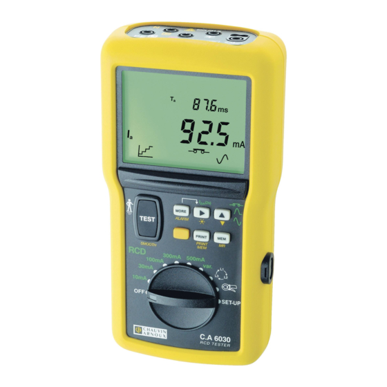
2. PRESENTATION 2.1. DEVICE 600V CAT III Connection terminals. > 550V Backlit LCD display unit. On the back: battery compartment cover and prop. To start the (2s) measurements. MORE ALARM TEST PRINT 6-Key keypad. LOOP / SMOOTH 300mA 500mA 100mA var. -
Page 7: Functions Of The Device
2.2. FUNCTIONS OF THE DEVICE The C.A 6030 loop and RCD tester is a portable device operating on battery power. It is used to check the safety of electrical installations. Measurement functions: „ voltage, „ frequency, „ test of the protection conductor (PE), „... -
Page 8: Keypad And Button
Position of the phase conductor on the outlet. Indication of connection of the auxiliary rod. Display of the smoothed measurement. Audible signal activated. Communication via the serial link in progress. Remaining battery life. Automatic standby switching of the device activated. Level of memory occupancy. - Page 9 „ Exit from the error mode. „ Smoothing of the measurement (SMOOTH). Activate before starting the measurement. TEST > 2s „ Compensation of the measurement leads (with the rotary switch set to LOOP/RCD). TEST 2.4.2. 2ND KEY (YELLOW) ...
- Page 10 „ On/Off switching of display unit backlighting. „ In the RCD settings of the switch, selection of the type of test (pulse or ramp) and of the pulse current value. > 2s 2.4.5. KEY „ In memory write, memory read, or printing, incrementing of the block (OBJ.) or test (TEST) number. „...
-
Page 11: Switch
2.5. SWITCH The switch has 10 settings, used to select the desired function: Switching the device off LOOP / RCD 10mA, 30mA, Test of RCD, rating 10, 30, 100, 300 or 500mA, or loop measurement only. 100mA, 300mA, 500mA LOOP / RCD var Test of RCD, rating 6 to 650mA (rating chosen in SET-UP). -
Page 12: Simple Use
3. SIMPLE USE The device is configured so that it can be used without modifying the parameters; this covers the great majority of the measurements to be made. For most measurements, you can therefore simply select the function by turning the switch, then pressing the TEST button. - Page 13 3.1.2. READING OF THE RESULT The voltage U and its frequency are displayed. The key is used to see voltages U and U . and their frequencies. 3.1.3. ERROR INDICATION The only errors reported in voltage measurement are values outside the voltage and/or frequency measurement range. To exit from the error mode, you must eliminate the cause of the error.
-
Page 14: Loop Measurement
3.2. LOOP MEASUREMENT The loop measurement is used to measure the earth resistance at a place where it is impossible to make a 3P earth measurement or to disconnect the earthing strip, a common situation in urban settings. The loop measurement does not trip RCDs located upstream of the measurement point. In a TT type installation, the loop impedance measurement is an easy way to make an earth measurement without planting any rods. - Page 15 Press the TEST button to start the measurement. The measurement stops automatically. TEST 3.2.2. READING OF THE RESULT During the measurement, the device displays “LOOP” and the dashes blink. At the end of the measurement, the device displays the following screen: Ω...
-
Page 16: Earth Measurement On Live Circuit
3.3. EARTH MEASUREMENT ON LIVE CIRCUIT This measurement is made without disconnecting the earth, with only one additional rod, saving time with respect to a conventional earth measurement with two auxiliary rods. In the case of a TT type installation, this measurement is a very simple way to measure the earth of frame grounds. The live earth measurement cannot be made in an IT installation because of the high earthing impedance of the power supply transformer, even its total isolation from earth. - Page 17 3.3.2. READING OF THE RESULT During the measurement, the device displays “-rA-” and the dashes blink. At the end of the measurement, the device displays the following screen: Ω The earth resistance, R , is the measurement result. 3.3.3. ERROR INDICATION The commonest errors in the case of a live earth measurement: „...
-
Page 18: Test Of Rcd
3.4. TEST OF RCD The device can perform two types of test on RCDs: „ a test of tripping in ramp mode, „ a test of tripping in pulse mode. The test in ramp mode serves to determine the current at which the RCD trips. The test in pulse mode serves to determine how long it takes for the RCD to trip. - Page 19 „ Then choose the type of test (if the tripping mode is not selected, it is not possible to choose the type of test): Perform a long press Each time the key is pressed again, the device proposes a type of test: on the ...
- Page 20 3.4.2. READING OF THE RESULT During the measurement, the device starts by displaying “LOOP” during the preliminary measurement; during the test of the RCD, it displays “rCd” and the dashes blink. (selective) RCD is normally tested at 2 I . The device counts 30 seconds between the preliminary measurement and the test of the RCD proper, in order to allow its demagnetization, and displays “SEC”.
-
Page 21: Direction Of Phase Rotation
3.5. DIRECTION OF PHASE ROTATION This measurement is made on a three-phase network. It is used to check the phase order of the network. This can be done by the “3-wire” method or by the “2-wire” method. 3.5.1. MAKING A “3-WIRE” MEASUREMENT Connect the measuring cable terminated by 3 leads to the device and to Set the switch to each of the phases: the red lead to L1, the yellow to L2 and the white to L3. - Page 22 Wait for the message “to L1” on the display unit, then connect the red lead to L1. yellow white 600V CAT III > 550V Wait for the message “open L1” to appear on the display unit and disconnect the red lead. When the message “to L3” is displayed, connect the red lead to L3.
-
Page 23: Current Measurement
3.6. CURRENT MEASUREMENT This measurement requires the use of an optional current clamp. It can measure very low currents (of the order of a few mA) like leakage currents, and high currents (of the order of a few hundred Amperes. 3.6.1. -
Page 24: Use In Detail
4. USE IN DETAIL In this part, all functions of the device are described, together with the measurement principles. You can parameterize the measurements using the function keys or by configuring the device in SET-UP (§5). Users are assumed to be at the reference earth potential. They must therefore not be insulated from the earth: they must not wear insulating shoes or gloves and must not use a plastic object to press the TEST button. -
Page 25: Compensation Of The Leads
> frequency outside measurement range, or a connection error. > To exit from the error mode, you must eliminate the cause of the error. Here, this is done by connecting the device to a network of which the voltage and frequency are compatible with the specifications of the device (see §9.2.1 and 9.2.2). 4.3. - Page 26 Perform a long press on the TEST button. > 2s During the measurement, the device displays “LEAd” and the symbol, and the dashes blink. TEST At the end of the measurement, the device displays the following screen: Ω The key is used to view the values of R and R ...
- Page 27 At the end of the measurement, the device displays the following screen: The device reports that the result found is greater than 5 Ω and withdraws the > compensation of the leads. Ω For exit from compensation of the leads, perform a second long press on the TEST key. >...
-
Page 28: Loop Measurement
4.4. LOOP MEASUREMENT 4.4.1. DESCRIPTION OF THE MEASUREMENT PRINCIPLE The device injects an adjustable measurement current, INtP = I x (0.1 to 0.5), chosen by the user, between L and PE. This weak current serves to avoid tripping the RCD of which the nominal current is indicated on the switch. The device thereby measures R and Z if INtP ≥... - Page 29 „ By activating smoothing of the measurement (SMOOTH). Without turning the switch, press the SMOOTH key. TEST „ To set the device to non-tripping mode, press the key until the symbol is displayed Press the TEST button to start the measurement. The measurement stops automatically. TEST 4.4.3.
- Page 30 Voltage U and its frequency before the start of the measurement. The key is used to view voltages U and U MORE Ω Alarm threshold, Z , has not been ALARM > crossed. Ω MORE 4.4.4. ERROR INDICATION The commonest errors in the case of a loop resistance measurement are: A connection error, for example no voltage on L, or N and PE reversed,...
- Page 31 or L and PE reversed. Voltage on the protection conductor too high. > Then check the earth resistance. To exit from the error mode, press the TEST button. TEST...
-
Page 32: Earth Measurement On Live Circuit
4.5. EARTH MEASUREMENT ON LIVE CIRCUIT This measurement is made without disconnecting the earth, with only one additional rod, saving time with respect to a conventional earth measurement with two auxiliary rods. In the case of a TT type installation, this measurement is a very simple way to measure the earth of frame grounds. This measurement cannot be made in an IT installation because of the high earthing impedance of the power supply transformer, even its total isolation from earth. - Page 33 „ By activating smoothing of the measurement (SMOOTH). Without turning the switch, press the SMOOTH key. TEST „ To set the device to non-tripping mode, press the key until the symbol is displayed. Press the TEST button to start the measurement. The measurement stops automatically TEST 4.5.3.
- Page 34 Ω The alarm threshold, R , and the fault voltage: A ALARM ALARM MORE The compensation of the L lead. The key is used to view the Ω compensation of the N and PE leads (R and R ) along with the resistance of the rod (R The conventional maximum contact voltage is displayed at the...
-
Page 35: Test Of Residual Current Device
4.6. TEST OF RESIDUAL CURRENT DEVICE The device can perform two types of test on RCDs: „ a tripping test in ramp mode, „ a tripping test in pulse mode. The ramp mode test determines the current at which the RCD trips. The pulse mode test determines how long it takes for the RCD to trip. - Page 36 If you have a current clamp, you can measure the leakage currents (see §3.6) at the RCD and so make allowance for them during the test, for the adjustment of INtP. To make a more accurate measurement of the fault voltage, plant the auxiliary rod at a distance of more than 25 metres from the earth electrode and connect it to the terminal of the device.
- Page 37 „ By activating the alarm. Set the switch to the RCD position corresponding to the rated current of the RCD that protects the installation. LOOP / LOOP / 300mA 500mA 300mA 500mA 100mA var. 100mA var. 30mA 30mA 10mA 10mA SET-UP SET-UP ...
- Page 38 „ The choice of the shape of the test signal: Press the key. At each press on the key, the device proposes a different test signal: signal starting with a positive half-wave, „ signal starting with a negative half-wave, „...
- Page 39 INtP, the current used for the loop measurement made before the test of the RCD (can be programmed in SET-UP). MORE Ω Loop impedance Z and, if the auxiliary rod is planted, the earth resistance, R Ω MORE ...
- Page 40 > Ω The resistance alarm threshold, R , and the impedance alarm ALARM threshold, Z > Ω MORE Ω The compensation of the L lead. The key is used to view the compensation of the N and PE leads (R and R ) along with the resistance of the rod (R...
- Page 41 „ The RCD failed to trip in the ramp mode test. But, to ensure the users’ safety, the RCD must trip at a current between I > and I . Check the wiring of the RCD. If there is nothing wrong with it, the RCD must be declared defective and replaced.
-
Page 42: Direction Of Phase Rotation
4.7. DIRECTION OF PHASE ROTATION This measurement is made on a three-phase network. It is used to check the phase order of the network. This can be done by the “3-wire” method or by the “2-wire” method. 4.7.1. DESCRIPTION OF THE MEASUREMENT PRINCIPLE In a “3-wire”... - Page 43 „ In a “2-wire” measurement, the frequencies measured are too different. „ In a “2-wire” measurement, the maximum time allowed for the voltage measurement, 10 seconds, is exceeded. To exit from the error mode, press the TEST button. TEST...
-
Page 44: Current Measurement
4.8. CURRENT MEASUREMENT This measurement requires the use of an optional current clamp. It can measure very low currents (of the order of a few mA) like fault currents, and high currents (of the order of a few hundred Amperes. 4.8.1. - Page 45 ALARM The current alarm threshold. > MORE 4.8.4. ERROR INDICATION The commonest errors in the case of a current measurement are: „ The clamp is not connected. „ The current or frequency is outside the measurement range. If the current measured by the clamp is too low. Use a clamp having a lower ratio or pass the conductor through the clamp several times to increase the measured current.
-
Page 46: Set-Up
5. SET-UP This function is used to: „ set the date and time, „ choose the type of power supply to the device and the whether or not the standby switching mode is activated, „ choose whether the audible signal is activated or not „... -
Page 47: Type Of Power Supply
Use the and keys to set the date (dAtE). Use the and keys to set the time (tiME). Press the MEM key one last time to validate the modifications and return to the PUSH btn screen. 5.3. -
Page 48: Audible Signal
5.4. AUDIBLE SIGNAL As default, the audible signal is activated. Use the key to activate (On) or deactivate (OFF) the audible signal (biP). When the audible signal is active, each key press, each crossing of an alarm threshold, and each >... -
Page 49: Configuration Of The Measurements
5.7. CONFIGURATION OF THE MEASUREMENTS 5.7.1. CHOICE OF REFERENCE VOLTAGE As default, U = 230 V. Press the MORE key. MORE Use the key to choose the reference voltage, U , for the calculation of Ik = U „... -
Page 50: Alarm Thresholds
5.7.4. CHOICE OF LOOP MEASUREMENT CURRENT As default INtP, = 0.4 I Press the MORE key a fourth time. MORE Use the key to choose the loop measurement current, INtP, as a function of the rated current of the RCD that protects the installation I , between 0.1 and 0.5 I Press the MORE key a... -
Page 51: Default Configuration
5.9. DEFAULT CONFIGURATION To restore the factory configuration of the device (dFLT), perform a long press on the TEST button. > 2s Only the date, the time, and any recorded measurements will not be modified. TEST TEST 5.10. COMMUNICATION RATE FOR PRINTING The default communication rate is 9600 Bauds ... -
Page 52: Storage
6. STORAGE 6.1. ORGANIZATION OF THE MEMORY The device has 100 memory locations to record measurements. These comprise measurements (TEST) that are arranged in blocks (OBJ.) A block number (OBJ.) may for example represent an installation and the measurement numbers (TEST) the various measurements made on the installation. -
Page 53: Readout
6.3. READOUT To read out a measurement, To choose the slot, use the and or keys to change the block (OBJ.) and press the MR key. measurement (TEST) numbers. Free slots are identified by FREE and occupied slots by rCd, VOLt, LOOP, rA, etc., depending on the type of measurement recorded. -
Page 54: Errors
Perform a long press on the MEM key. The selected block or measurement is erased and OCC is replaced by FREE, followed by a return to the PUSH btn screen. > 2s 6.4.2. COMPLETE ERASURE The whole memory is erased and the display “Clr ALL” is replaced by “FrEE ALL”. Perform a long press on the MEM key. -
Page 55: Printing
7. PRINTING This function requires the use of a serial printer, available as an option. It is used to print a measurement as soon as it is over. Connect the printer to mains, then connect it to the device using the optical-RS232 communication cord provided. Insert the provided metallic adapter between the cord and the printer. -
Page 56: Data Export Software
8. DATA EXPORT SOFTWARE The data export software, Transfertview, is used to recover the recorded measurements and transfer them into an Excel™ file. Start by installing Transfertview using the provided CD. Power up the device, then connect it to the PC using the optical-RS232 communication cord. Start the Transfertview software, then follow the instructions. -
Page 57: Technical Characteristics
9. TECHNICAL CHARACTERISTICS 9.1. REFERENCE CONDITIONS Quantity of influence Reference values Temperature 20 ± 3 °C Relative humidity 45 to 55% RH Supply voltage 8.5 ± 0.5 V Electric field < 1 V/m Magnetic field < 40 A/m The intrinsic uncertainty is the error defined under the reference conditions. The operating uncertainty includes the intrinsic uncertainty plus the effects of variation of the quantities of influence (supply voltage, temperature, spurious currents, etc.) as defined in standard IEC-61557. - Page 58 Specified measurement range 15.3 – 399.9 Hz 400.0 – 499.9 Hz Resolution 0.1 Hz 1 Hz Intrinsic uncertainty ± (0.1% + 1 ct) 9.2.3. LOOP IMPEDANCE AND LIVE EARTH MEASUREMENTS Particular reference conditions: Voltage of the installation: 90 to 550 V. Frequency of the installation: 15.3 to 65 Hz.
- Page 59 9.2.4. TEST OF RESIDUAL CURRENT DEVICE Particular reference conditions: Voltage of the installation: 90 to 550 V. Frequency of the installation: 15.3 to 65 Hz. Contact voltage (potential of the protective conductor with respect to the local earth): < 5 V. Resistance of the voltage probe (if used): ≤...
- Page 60 Characteristics of the trip time (T Pulse mode Ramp mode Specified measurement range 5.0 – 399.9 ms 400 - 500 ms 10.0 – 200.0 ms Resolution 0.1 ms 1 ms 0.1 ms Intrinsic uncertainty ± 2 ms ± 2 ms Characteristics of the short-circuit current calculation: See §9.2.3.
-
Page 61: Variations In The Range Of Use
Characteristics: „ Frequency range (approximately ± 6% with respect to the theoretical value): between 15.7 and 17.7 Hz (for 16.67 Hz) or between 47 and 53 Hz (for 50 Hz) or between 56 and 64 Hz (for 60 Hz). „ Reference period acquisition time after contact: ≤ 500 ms (2-wire mode only). „... -
Page 62: Intrinsic Uncertainty And Operating Uncertainty
9.3.4. DIRECTION OF PHASE ROTATION No quantity of influence 9.3.5. CURRENT MEASUREMENT Variation of the measurement Quantities of influence Limits of the range of use Typical Maximum Temperature -10 … + 55 °C 1%/10 °C ± 1ct 2%/10 °C + 2 ct Relative humidity 10 …... -
Page 63: Mechanical Characteristics
9.7. MECHANICAL CHARACTERISTICS Dimensions (L x l x H) 211 x 108 x 60 mm Weight approximately 850 g Protection class IP 54 per IEC 60 529 IK 04 per IEC 50102 Free fall test per IEC 61010-1 9.8. CONFORMITY TO INTERNATIONAL STANDARDS The device is in conformity with IEC 61010-1, 600V CAT III. -
Page 64: Definition Of Symbols
10. DEFINITION OF SYMBOLS Here is a list of the symbols used in this document and on the display unit of the device. AC (Alternating Current) signal. DC (Direct Current) signal. Hertz: indicates the frequency of the signal. current. current alarm threshold. ALARM effective RCD operating current (ramp mode test). -
Page 65: Maintenance
11. MAINTENANCE The manufacturer cannot be held liable for any accident that occurs following a repair not performed by its customer service department or by an approved repairer. 11.1. CLEANING Disconnect the unit completely and turn the rotary switch to OFF. Use a soft cloth, dampened with soapy water. -
Page 66: Updating Of The Internal Software
11.5. UPDATING OF THE INTERNAL SOFTWARE With a view to providing, at all times, the best possible service in terms of performance and technical upgrades, Chauvin Arnoux invites you to update the embedded software of the device by downloading the new version, available free of charge on our web site. -
Page 67: Warranty
12. WARRANTY Except as otherwise stated, our warranty is valid for twelve months starting from the date on which the equipment was sold. Extract from our General Conditions of Sale provided on request. The warranty does not apply in the following cases: „... - Page 68 FRANCE INTERNATIONAL Chauvin Arnoux Group Chauvin Arnoux Group 190, rue Championnet Tél : +33 1 44 85 44 38 75876 PARIS Cedex 18 Fax : +33 1 46 27 95 69 Tél : +33 1 44 85 44 85 Fax : +33 1 46 27 73 89 Our international contacts info@chauvin-arnoux.com...
Need help?
Do you have a question about the C.A 6030 and is the answer not in the manual?
Questions and answers