Table of Contents
Advertisement
Quick Links
Advertisement
Table of Contents

Related Manuals for Eaton 93PS-8(20)-20(-C)


Summary of Contents for Eaton 93PS-8(20)-20(-C)
- Page 1 User's and installation guide Eaton 93PS UPS 8–40 kW P-164000493...
- Page 2 The contents of this manual are the copyright of the publisher and may not be reproduced (even extracts) without the written approval of Eaton Corporation. Every care has been taken to ensure the accuracy of the information contained in this manual, but no liability can be accepted for any errors or omission.
-
Page 3: Table Of Contents
Maintenance Bypass Switch (optional)......29 3.5.2 Field Installed UPM (accessory)........29 Battery system................30 Basic system configurations............. 30 UPS installation plan and unpacking............33 Creating an installation plan............33 © Eaton Corporation plc 2016. All rights reserved. Revision: 003 Document ID: P-164000493 3 (104) - Page 4 System events............. 76 7.1.4 Menu structure of the 93PS UPS.........76 Signing in.................. 80 System control instructions............80 7.3.1 Starting the UPS system in the double conversion mode...................80 © Eaton Corporation plc 2016. All rights reserved. Revision: 003 Document ID: P-164000493 4 (104)
- Page 5 Maintenance training..............97 Technical data..................98 Directives and standards............98 UPS system input..............98 UPS system output..............99 UPS environmental specifications.......... 100 Battery specification..............100 Warranty....................102 10.1 General................... 102 © Eaton Corporation plc 2016. All rights reserved. Revision: 003 Document ID: P-164000493 5 (104)
- Page 6 Eaton 93PS UPS 8–40 kW User's and installation guide 10.2 Whom to contact in case of Warranty........103 © Eaton Corporation plc 2016. All rights reserved. Revision: 003 Document ID: P-164000493 6 (104)
-
Page 7: How To Read This Manual
Explosion and fire hazard Electrical hazard Corrosive hazard Battery hazard 1.2.2 Prohibited action symbols These symbols are used to indicate an action that should not be taken. © Eaton Corporation plc 2016. All rights reserved. Revision: 003 Document ID: P-164000493 7 (104) -
Page 8: Mandatory Action Symbols
• • Screen type represents information that appears on the screen or LCD. Glossary This document uses the following acronyms to refer to Eaton UPS products or their parts: Table 1: Glossary of acronyms Advanced Battery Management Bybass Input Breaker... - Page 9 Module Output Breaker REPO Remote Emergency Power-off Rectifier Input Breaker Silicon-controlled Rectifier STSW Static Switch Uninterruptible Power Module Uninterruptible Power Supply VMMS Variable Module Management System © Eaton Corporation plc 2016. All rights reserved. Revision: 003 Document ID: P-164000493 9 (104)
-
Page 10: Safety Instructions
These instructions are also available for download at www.eaton.eu/ 93ps. DANGER Operations inside the UPS must be performed by an authorized Eaton Customer Service Engineer or by other qualified service personnel authorized by Eaton. There are no user-serviceable parts inside the UPS. - Page 11 Do not install or operate the UPS system close to gas or electric heat sources. Keep the operating environment within the parameters stated in this document. © Eaton Corporation plc 2016. All rights reserved. Revision: 003 Document ID: P-164000493 11 (104)
-
Page 12: Audience
Declarations of conformity with UPS harmonized standards and directives EN www.eaton.eu or by 62040-1 (Safety) and EN 62040-2 (EMC) are available at contacting your nearest Eaton office or authorized partner. User precautions The only permitted user operations are as follows: •... -
Page 13: Environment
RISK OF ELECTRIC SHOCK Indicates that a risk of electric shock is present and the associated warning should be observed. © Eaton Corporation plc 2016. All rights reserved. Revision: 003 Document ID: P-164000493 13 (104) -
Page 14: For More Information
Note: For more information about the installation space, safe operation and working, see IEC 62485-2: Safety requirements for secondary batteries and battery installations. © Eaton Corporation plc 2016. All rights reserved. Revision: 003 Document ID: P-164000493 14 (104) -
Page 15: Introduction To Eaton Ups
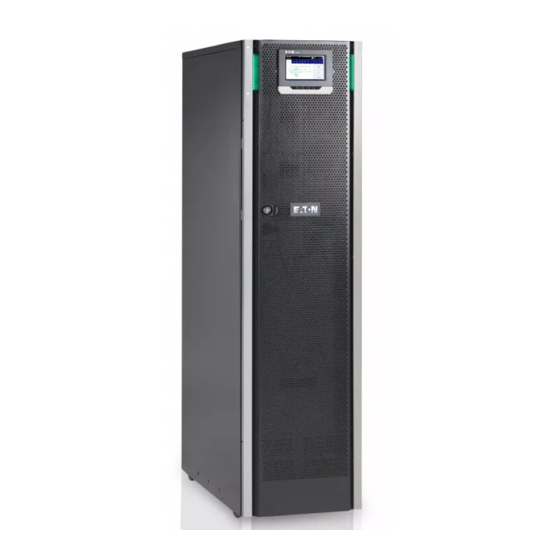
Eaton 93PS UPS 8–40 kW User's and installation guide Introduction to Eaton UPS Figure 1. Eaton 93PS UPS 20 kW C-model frame, 93PS UPS 20 kW standard frame and 93PS UPS 40 kW frame The Eaton ® 93PS uninterruptible power supply (UPS) is a true online,... - Page 16 Note: Startup and operational checks must be performed by an authorized Eaton Customer Service Engineer or by other qualified service personnel authorized by Eaton, or the terms specified in the Warranty (see Chapter become void. This service is offered as part of the sales contract for the UPS.
-
Page 17: Looking Inside The Ups System
Eaton 93PS UPS 8–40 kW User's and installation guide Looking inside the UPS system Figure 2. Looking inside the Eaton 93PS UPS 20 kW standard and C-model frames Figure 3. Looking inside the Eaton 93PS 40 kW frame Control panel... -
Page 18: Ups Operating Modes
In the Energy Saver System (ESS) mode, the critical load is supported securely by utility power through the static bypass switch with double conversion available on-demand with typically less than a 2 ms transition © Eaton Corporation plc 2016. All rights reserved. Revision: 003 Document ID: P-164000493 18 (104) -
Page 19: Normal Operating Modes
3.2.1.1 Double conversion mode Figure shows the path of electrical power through the UPS system when the UPS is operating in the double conversion mode. © Eaton Corporation plc 2016. All rights reserved. Revision: 003 Document ID: P-164000493 19 (104) - Page 20 When utility power returns, the UPS returns automatically to the double conversion mode. © Eaton Corporation plc 2016. All rights reserved. Revision: 003 Document ID: P-164000493 20 (104)
- Page 21 Energy Saver System mode Figure shows the path of electrical power through the UPS system when the UPS is operating in the Energy Saver System (ESS) mode. © Eaton Corporation plc 2016. All rights reserved. Revision: 003 Document ID: P-164000493 21 (104)
- Page 22 When operating in the ESS mode, the UPS's superior detection and control algorithms continuously monitor the incoming power quality and allow fast © Eaton Corporation plc 2016. All rights reserved. Revision: 003 Document ID: P-164000493 22 (104)
-
Page 23: Stored Energy And Battery Mode
DC power, which is converted to regulated output power by the inverter. Figure shows the path of electrical power through the UPS system when operating in the battery mode. © Eaton Corporation plc 2016. All rights reserved. Revision: 003 Document ID: P-164000493 23 (104) - Page 24 Unless utility power is restored, the output can be supported for a © Eaton Corporation plc 2016. All rights reserved. Revision: 003 Document ID: P-164000493...
-
Page 25: Bypass Mode
(for example UPS internal failure), the UPS will remain on bypass operation. Figure shows the path of electrical power through the UPS system when operating in the bypass mode. © Eaton Corporation plc 2016. All rights reserved. Revision: 003 Document ID: P-164000493 25 (104) - Page 26 The backfeed protection is normally always closed, ready to support the static switch unless the bypass input source becomes unavailable. © Eaton Corporation plc 2016. All rights reserved. Revision: 003 Document ID: P-164000493 26 (104)
-
Page 27: Ups Features
The Eaton Powerware Hot Sync technology is an algorithm that eliminates the single point of failure in a parallel system and therefore enhances system reliability. The Hot Sync technology is incorporated in all Eaton 93PS UPSs, and it is utilized in both multi-module internal parallel and external parallel systems. -
Page 28: Power Conditioner
® Sync Control maintains the critical load outputs of two separate UPS systems in synchronization. Use of the Eaton Fixed Master Sync Control provides uninterrupted transfer of the load from one load bus to another by means of downstream, dual-source, solid-state transfer switches. Without the load sync option, the two system output (critical load) buses can become out of phase with each other. -
Page 29: Software And Connectivity Features
Intelligent Power software products offer tools for monitoring and managing power devices across the network. See Chapter for more information. Options and accessories Contact your Eaton sales representative for more information about the available options and accessories. 3.5.1 Maintenance Bypass Switch (optional) -
Page 30: Battery System
The Eaton 93PS 8–40 kW UPS are equipped with internal batteries to provide full load runtime of 5–60 minutes depending on the UPS rating. This does not apply to the C-model, which has no internal batteries. - Page 31 With a 93PS UPS 20 kW frame, a single UPS frame can house only one power module. UPS options and accessories © Eaton Corporation plc 2016. All rights reserved. Revision: 003 Document ID: P-164000493 31 (104)
- Page 32 Integrated backfeed protection Standard Additional options and accessories are also available. These include different software and connectivity options and external switchgear and power distribution options. © Eaton Corporation plc 2016. All rights reserved. Revision: 003 Document ID: P-164000493 32 (104)
-
Page 33: Ups Installation Plan And Unpacking
Note: Startup and operational checks must be performed by an authorized Eaton Customer Service Engineer or by other qualified service personnel authorized by Eaton, or the terms specified in the Warranty (see Chapter become void. This service is offered as a part of the sales contract for the UPS. -
Page 34: Installation Checklist
(OPTIONAL) Accessories are mounted in their installed locations and their wiring is terminated inside the UPS cabinet. Start-up and operational checks are performed by an authorized Eaton Customer Service Engineer. Site preparations For the UPS system to operate at peak efficiency, the installation site must meet the environmental parameters outlined in these instructions. -
Page 35: Environmental And Installation Considerations
20 kW 20 kW C-model 40 kW frame frame frame Shipping weight 293 kg 98 kg 558 kg Installed weight 280 kg 86 kg 532 kg © Eaton Corporation plc 2016. All rights reserved. Revision: 003 Document ID: P-164000493 35 (104) - Page 36 150 mm 250 mm From the side of the cabinet 0 mm 0 mm * Applies to the 93PS 20 kW C-model frame as well. © Eaton Corporation plc 2016. All rights reserved. Revision: 003 Document ID: P-164000493 36 (104)
- Page 37 For ventilation requirements, see 93PS heat rejection in Table Table 7: Air conditioning or ventilation requirements during full load operation Heat rejection Heat rejection (BTU/h x 1,000) (kW) 8 kW 1.17 © Eaton Corporation plc 2016. All rights reserved. Revision: 003 Document ID: P-164000493 37 (104)
-
Page 38: Ups System Power Wiring Preparations
For larger batteries, the ventilation air flow must be recalculated. For the dimensions of the 93PS UPS cabinets, see Figure Figure 9. The dimensions of the Eaton 93PS UPS 20 kW C-model frame, the 93PS UPS 20 kW frame, and the 93PS UPS 40 kW frame, respectively. 4.3.2... - Page 39 Table 8: Minimum recommended multi-core cable and fuse sizes for rectifier and bypass input and UPS output cables UPS rating (kW) Cable [mm 4*2.5 4*10 4*10 4*16 4*25 Rectifier fuse [A] Bypass fuse [A] © Eaton Corporation plc 2016. All rights reserved. Revision: 003 Document ID: P-164000493 39 (104)
- Page 40 Cable sizing is based on the standard IEC 60364-5-52 table B.52.2 and IEC 60364-5-54 table B.54.2. Sizing is for 70 ºC rated copper cables. When connecting external batteries to 93PS UPS, Eaton recommends that you use the following NZM series molded case circuit breakers:...
- Page 41 NOTE: Maximum string length for the 93PS C-model is 36 blocks, 216 cells (432 V) Note: Contact your Eaton sales representative for more information about the circuit breakers, or if you need help choosing the right model for your UPS system.
- Page 42 Maximum output/bypass current calculated at continuous 125% overload and at -15% voltage tolerance. Maximum battery current calculated at rated load and 1.67 V cell voltage for the default 32 block string length. © Eaton Corporation plc 2016. All rights reserved. Revision: 003 Document ID: P-164000493 42 (104)
- Page 43 User's and installation guide Figure 10. Power cable terminals in the 93PS 20 kW frame Figure 11. Power cable terminals in the 93PS 40 kW frame © Eaton Corporation plc 2016. All rights reserved. Revision: 003 Document ID: P-164000493 43 (104)
- Page 44 The line-to-line unbalanced output capability of the UPS is limited only by the full load per phase current values for AC output to critical load shown in Table The recommended line-to-line load unbalance is 50% or less. © Eaton Corporation plc 2016. All rights reserved. Revision: 003 Document ID: P-164000493 44 (104)
-
Page 45: Unpacking And Unloading The Ups
Insert the forks of the forklift between the skids on the bottom of the unit. © Eaton Corporation plc 2016. All rights reserved. Revision: 003 Document ID: P-164000493 45 (104) - Page 46 Place the ramp on the floor and attach it to the pallet with nails or screws so that it can be safely used for wheeling the UPS off the pallet. © Eaton Corporation plc 2016. All rights reserved. Revision: 003 Document ID: P-164000493 46 (104)
- Page 47 UPS cabinet and to the pallet. Remove the shipping brackets. Note: After you have removed the shipping brackets, move the unit immediately away from the pallet. © Eaton Corporation plc 2016. All rights reserved. Revision: 003 Document ID: P-164000493 47 (104)
- Page 48 In addition, attach the shipping brackets to the cabinet and the pallet. © Eaton Corporation plc 2016. All rights reserved. Revision: 003 Document ID: P-164000493 48 (104)
-
Page 49: Ups System Installation
The electrical installation procedure is described in the following section. The installation inspection and the initial start-up of the UPS and installing an extra battery cabinet must be carried out by an authorized Eaton Customer Service Engineer or by other qualified service personnel authorized by Eaton. - Page 50 Figure 13. Gland plate and connector locations in the 93PS UPS 40 kW frame Connectors Gland plate To gain access to the terminal blocks, remove the screws securing the gland plate at the back of the UPS. © Eaton Corporation plc 2016. All rights reserved. Revision: 003 Document ID: P-164000493 50 (104)
- Page 51 Only use cables specified by Eaton. Slide the internal battery trays into place and mount the locking brackets. © Eaton Corporation plc 2016. All rights reserved. Revision: 003 Document ID: P-164000493 51 (104)
-
Page 52: Battery System Installation
Ground the external battery cabinet to the UPS. The default battery settings of the UPS are for 12 V VRLA batteries. If you need to use any other type of batteries, contact your Eaton representative. For the battery specification, see Section 5.2.1... -
Page 53: Installing Ups External Battery Cabinet And Battery Power Cabling
The battery cabinet can be located freely of the 93PS UPS cabinet. All the wiring goes through the back wall of the UPS cabinet. © Eaton Corporation plc 2016. All rights reserved. Revision: 003 Document ID: P-164000493 53 (104) -
Page 54: Installing A Remote Epo Switch
93PS UPS contains a total of 5 signal input connectors for operators which can be used for giving remote control commands to the UPS. User interface © Eaton Corporation plc 2016. All rights reserved. Revision: 003 Document ID: P-164000493 54 (104) -
Page 55: Installing Customer Input Signals Interface
Wire entry for the battery breaker signal wiring is located in the middle of the UPS cabinet. Punch holes are located on the left or right side panel, back wall or bottom plate. 5.2.1 See Section for installation instructions. © Eaton Corporation plc 2016. All rights reserved. Revision: 003 Document ID: P-164000493 55 (104) -
Page 56: Relay Output Interface Connections
Additional relay outputs are available with mini-slot cards. Relay outputs can be configured to be activated by various events. Configuration can be done by an authorized Eaton Customer Service Engineer or by other qualified service personnel authorized by Eaton. 5.5.4 Industrial Relay Card interface connections Relays K1 through K5 are identical in function. -
Page 57: Minislot Interface Connections
5.5.5 MiniSlot interface connections For MiniSlot accessories and communication devices selection, see Chapter For installation and setup of a MiniSlot card, please contact your Eaton representative. To install wiring to the connections: If not already installed, install the LAN drops. -
Page 58: Wiring Parallel 93Ps Ups Systems
UPS must be a minimum of 95% of the length of the longest wire. The measurement is with respect to where the UPS’s outputs are tied. Dual source © Eaton Corporation plc 2016. All rights reserved. Revision: 003 Document ID: P-164000493 58 (104) - Page 59 Users without MOBs installed can simply leave the MOB signal input disabled. The user should be aware that systems without MOB have limited maintenance capability. Parallel system cabling © Eaton Corporation plc 2016. All rights reserved. Revision: 003 Document ID: P-164000493 59 (104)
-
Page 60: Control Signals Overview
2 controls signals (External CAN Network, Bypass Pull-Chain) are required for external paralleling. Both of these control signals are fault-tolerant and alarmed when disconnected. External CAN (ECAN) © Eaton Corporation plc 2016. All rights reserved. Revision: 003 Document ID: P-164000493 60 (104) -
Page 61: Installing Bypass Control Wiring
Terminal blocks TB6, TB7 and TB8 are for external parallel control signals (see Figure and Figure The Phoenix Contact FRONT-MSTB 2,5/2-STF-5,08 and 2,6/4-SFT-5,08 plug components are used for cable wiring termination. © Eaton Corporation plc 2016. All rights reserved. Revision: 003 Document ID: P-164000493 61 (104) - Page 62 Note: This drawing is for distributed bypass wiring purposes and it is not a floor layout plan. UPSs can be placed in any physical order. © Eaton Corporation plc 2016. All rights reserved. Revision: 003 Document ID: P-164000493 62 (104)
- Page 63 External CAN connections between the UPS cabinets require shielded twisted pair wire. Use twisted pair wiring between the UPS and MOB AUX contacts. Always confirm contact operation prior to wiring. © Eaton Corporation plc 2016. All rights reserved. Revision: 003 Document ID: P-164000493 63 (104)
-
Page 64: Ups System Interface Wiring Preparation
Alarm relay contacts have a maximum current rating of 5 A and a switched voltage rating of 30 VAC (RMS) and 30 VDC. • Alarm relay wiring must be a minimum of 0.75 mm © Eaton Corporation plc 2016. All rights reserved. Revision: 003 Document ID: P-164000493 64 (104) -
Page 65: Communication Interfaces
Eaton 93PS UPS 8–40 kW User's and installation guide Communication interfaces This section describes the communication features of the Eaton 93PS UPS. CAUTION All the communication interfaces are SELV circuits. When connecting to other equipment, make sure that you maintain this characteristic. -
Page 66: Minislot Cards
USB2, USB device (connection to TB5, relay output computer) MiniSlot cards The Eaton 93PS UPS has 2 MiniSlot communication bays. To install a MiniSlot 5.5.5 card, follow the instructions in Section The UPS is compatible with the following MiniSlot cards: •... - Page 67 Normally Open or Normally Closed setup for each output. For information on how to configure Industrial Relay Card-MS, see Section © Eaton Corporation plc 2016. All rights reserved. Revision: 003 Document ID: P-164000493 67 (104)
-
Page 68: Intelligent Power Software
(IPM) application. Intelligent Power Software is delivered on a CD with the UPS. Alternatively, you can download it from the Eaton web page. Some of the advanced features of IPM require a license, contact your Eaton representative for details. ©... -
Page 69: Signal Input Monitoring
In the home screen of the display, click the lock icon in the top right corner to type in the service password. In the sign in window, click the password field containing the 4 dots. © Eaton Corporation plc 2016. All rights reserved. Revision: 003 Document ID: P-164000493 69 (104) - Page 70 It is possible to set 8 different events for the native relay. If any of the set events occurs, the relay is activated • MiniSlot 1 • MiniSlot 2 © Eaton Corporation plc 2016. All rights reserved. Revision: 003 Document ID: P-164000493 70 (104)
- Page 71 Relay 4: #261 On Bypass (LED is lit) • Relay 5: #15 Low Battery warning Alternatively, you can configure the relays with any event you want. © Eaton Corporation plc 2016. All rights reserved. Revision: 003 Document ID: P-164000493 71 (104)
- Page 72 Cable exit opening for up to 12 mm (½”) K1 thru K5 terminal connections for relay conduit contacts to operator's monitoring equipment Signal input connector with voltage supply © Eaton Corporation plc 2016. All rights reserved. Revision: 003 Document ID: P-164000493 72 (104)
-
Page 73: Ups Operating Instructions
Settings > Information. If the UPS need to be operated with another voltage or frequency, contact your closest Eaton office or Eaton authorized partner. Note: The UPS is not a measuring device. All the displayed measurements are approximate values only. -
Page 74: Status Indicators
The UPS is in the battery mode. Because the bat- mode tery mode is a normal condition of the UPS, the green indicator for normal operation also remains illuminated. © Eaton Corporation plc 2016. All rights reserved. Revision: 003 Document ID: P-164000493 74 (104) - Page 75 Since the battery mode is a normal condition of the UPS, the green symbol for normal operation is also illumi- nated below the display. Bypass mode © Eaton Corporation plc 2016. All rights reserved. Revision: 003 Document ID: P-164000493 75 (104)
-
Page 76: System Events
Table 14: Menu structure of the 93PS UPS Main menu Submenu Functions Home An overview of the UPS operation, including informa- tion on load, efficiency and consumption. © Eaton Corporation plc 2016. All rights reserved. Revision: 003 Document ID: P-164000493 76 (104) - Page 77 Output meters Detailed information on UPS or system output me- ters. UPM Power Battery meters Detailed information on UPS or system battery me- ters. © Eaton Corporation plc 2016. All rights reserved. Revision: 003 Document ID: P-164000493 77 (104)
- Page 78 • Configure VMMS: • Enable • Disable • Configure Enable High Alert Clear status ABM: • Enable • Disable • Configure Clear Alarms Clear Logs © Eaton Corporation plc 2016. All rights reserved. Revision: 003 Document ID: P-164000493 78 (104)
- Page 79 Change the date and time, change the clock format or enable/ disable NTP clock setup. GSM modem. Call Service Send automatic e-mail to the service center in case of a failure. © Eaton Corporation plc 2016. All rights reserved. Revision: 003 Document ID: P-164000493 79 (104)
-
Page 80: Signing In
Check that the rectifier input switch S1 closed. Check that the battery breaker CB1 is closed. Close the UPS front door. Close the UPS input feeder circuit breaker. © Eaton Corporation plc 2016. All rights reserved. Revision: 003 Document ID: P-164000493 80 (104) -
Page 81: Starting The Ups System In The Bypass Mode
Close the UPS bypass input feeder circuit breaker. Wait for the UPS control panel to become active and indicate logic power. Repeat steps 1-7 for each single UPS in the system. © Eaton Corporation plc 2016. All rights reserved. Revision: 003 Document ID: P-164000493 81 (104) -
Page 82: Transferring From The Double Conversion Mode To The Bypass Mode
The UPS system transfers to the double conversion mode. If there is not enough UPM capacity available, the system remains in the bypass mode and an alarm sounds. © Eaton Corporation plc 2016. All rights reserved. Revision: 003 Document ID: P-164000493 82 (104) -
Page 83: Transferring From The Double Conversion Mode To The Energy Saver System Mode
Saver System mode Note: Note that the Energy Saver System mode commands are displayed only if enabled at the factory or by an authorized Eaton Customer Service Engineer . To transfer the critical load to the Energy Saver System mode: In the home screen, press Controls. -
Page 84: De-Energizing The Critical Load
Section 7.3.2 CAUTION Do not attempt to restart the system after Load Off until you have identified and cleared the cause of the shutdown. © Eaton Corporation plc 2016. All rights reserved. Revision: 003 Document ID: P-164000493 84 (104) -
Page 85: Ups Control Instructions
UPS system to achieve the double conversion mode. The UPS system is now operating in the double conversion mode and the green status indicator for normal operation is illuminated. © Eaton Corporation plc 2016. All rights reserved. Revision: 003 Document ID: P-164000493 85 (104) -
Page 86: Shutting Down A Single Ups
10. Check that there are no active alarms. 11. In the System controls screen, press Module controls. The Select module screen is displayed. 12. Select the UPM you want to start. © Eaton Corporation plc 2016. All rights reserved. Revision: 003 Document ID: P-164000493 86 (104) -
Page 87: Shutting Down The Upms
When the EPO switch is activated, all power to the critical load is lost. Use this feature only in case of emergency. Note: The following instructions are for the EPO switch supplied by Eaton Corporation. If you are using a customer-supplied EPO switch, it may not activate in the same way. -
Page 88: Turning The Ups From The Double Conversion Mode To The Maintenance Bypass Mode
UPS internal functionality. To turn the UPS to maintenance bypass: Follow the normal start position: © Eaton Corporation plc 2016. All rights reserved. Revision: 003 Document ID: P-164000493 88 (104) - Page 89 Turn off the rectifier switch to disconnect the UPS rectifier input. Turn off the static bypass switch to disconnect the UPS bypass input. The UPS is now in the maintenance bypass mode: © Eaton Corporation plc 2016. All rights reserved. Revision: 003 Document ID: P-164000493 89 (104)
-
Page 90: Turning The Ups From The Maintenance Bypass Mode To
Figure 35. Maintenance bypass mode Static bypass input Maintenance Bypass Switch (MBS) Rectifier input C Out Turn on the rectifier switch to connect rectifier input to the UPS. © Eaton Corporation plc 2016. All rights reserved. Revision: 003 Document ID: P-164000493 90 (104) - Page 91 Section The UPS is now in the double conversion mode. Figure 36. Double conversion mode Static bypass input Maintenance Bypass Switch (MBS) Rectifier input © Eaton Corporation plc 2016. All rights reserved. Revision: 003 Document ID: P-164000493 91 (104)
-
Page 92: Ups Maintenance
UPS input is connected through external isolators that, when opened, isolate the neutral. These warning labels can be obtained from your local service representative. © Eaton Corporation plc 2016. All rights reserved. Revision: 003 Document ID: P-164000493 92 (104) -
Page 93: Performing Preventive Maintenance
Eaton. Only the actions described in Section 8.2.2 Section are allowed to be performed by the user. See the Eaton 93PS UPS 8–40 kW Service Manual for further information. © Eaton Corporation plc 2016. All rights reserved. Revision: 003... -
Page 94: Daily Maintenance
Only authorized personnel that are familiar with the maintenance and servicing of the UPS system are allowed to perform annual preventive maintenance. Contact your service representative for more information about service offerings. © Eaton Corporation plc 2016. All rights reserved. Revision: 003 Document ID: P-164000493 94 (104) -
Page 95: Battery Maintenance
Do not discard waste electrical or electronic equipment in the trash. For proper disposal, contact your local collecting/recycling/reuse or hazardous waste center and follow the local legislation. The following symbols indicate a product requiring special handling: © Eaton Corporation plc 2016. All rights reserved. Revision: 003 Document ID: P-164000493 95 (104) - Page 96 Do not discard of unwanted batteries or battery material in the public waste disposal system. Follow all the applicable local regulations regarding the storage, handling and disposal of batteries and battery materials. © Eaton Corporation plc 2016. All rights reserved. Revision: 003 Document ID: P-164000493 96 (104)
-
Page 97: Maintenance Training
Eaton 93PS UPS 8–40 kW User's and installation guide Maintenance training For more information about training and other services, contact your Eaton representative. © Eaton Corporation plc 2016. All rights reserved. Revision: 003 Document ID: P-164000493 97 (104) -
Page 98: Technical Data
Eaton 93PS UPS 8–40 kW User's and installation guide Technical data For a complete technical specification, contact your Eaton representative. Due to continuous product improvement programs, specifications are subject to change without notice. Directives and standards Safety IEC 62040-1: Uninterruptible power systems (UPS) - Part... -
Page 99: Ups System Output
Overload capability at ambient 40 °C (in Continuous ≤ 125% load the bypass mode) Transient ≤ 1000% RMS current for 20 ms Note! Bypass fuses may limit the overload capability © Eaton Corporation plc 2016. All rights reserved. Revision: 003 Document ID: P-164000493 99 (104) -
Page 100: Ups Environmental Specifications
384 V (32 blocks), 336 V (28 blocks), 480 V (40 blocks) Recharge profile Constant voltage, constant current charg- ing (U-I characteristics), ABM or float charge © Eaton Corporation plc 2016. All rights reserved. Revision: 003 Document ID: P-164000493 100 (104) - Page 101 20 A) Note: the maximum charge current is 25 A per one 20 kW UPM and 18 A per one 15 kW UPM Battery start option © Eaton Corporation plc 2016. All rights reserved. Revision: 003 Document ID: P-164000493 101 (104)
-
Page 102: Warranty
The warranty is only valid if the installation inspection and initial startup of the UPS unit is carried out by an authorized Eaton Customer Service Engineer or by other qualified service personnel authorized by Eaton. Service and maintenance of the UPS shall also be performed only by an authorized Eaton Customer Service Engineer or by other qualified service personnel authorized by Eaton. - Page 103 Purchase order number and purchase order date • Installation date • Serial number and part number of the unit (information available on the unit's label) © Eaton Corporation plc 2016. All rights reserved. Revision: 003 Document ID: P-164000493 103 (104)
- Page 104 Eaton Power Quality Oy Koskelontie 13 FI-02920 Espoo, Finland www.eaton.eu...
Need help?
Do you have a question about the 93PS-8(20)-20(-C) and is the answer not in the manual?
Questions and answers