Table of Contents
Advertisement
Quick Links
Advertisement
Table of Contents

Related Manuals for IDTECK LX006


Summary of Contents for IDTECK LX006
- Page 1 User’s Manual LX006 Fingerprint Identification Proximity Reader...
-
Page 2: Table Of Contents
TABLE OF CONTENTS 1. IMPORTANT SAFETY INSTRUCTIONS .......................... 4 2. FEATURES ..................................5 3. SPECIFICATION ................................7 4. IDENTIFYNG SUPPLIED PARTS ............................ 9 5. PRODUCT EXPLANATION ............................10 5.1 PANEL LAYOUT ..............................10 5.2 CONNECTION LAYOUT............................10 5.3 COLOR CODED & WIRING TABLE ........................11 6. - Page 3 9.1 INITIALIZATION OF LX006 ..........................25 9.2 COMMUNICATION ID SETTING ......................... 25 10. OPERATION MODE ..............................26 10.1 MASTER CARD REGISTRATION MODE ......................26 10.1.1 MASTER CARD REGISTRATION ......................26 10.1.2 MASTER CARD CHANGE........................26 10.1.3 MASTER CARD FUNCTION......................... 26 10.2 REGISTRATION / DELETION MODE .......................
-
Page 4: Important Safety Instructions
1. IMPORTANT SAFETY INSTRUCTIONS The description below is to keep user’s safety and prevent any product damage. Please fully read these instruction and use the product properly. Danger: This symbol indicates that incorrect handling of the product may result in serious injury or death. -
Page 5: Features
The LX006 is a Fingerprint and Proximity Reader compatible with existing proximity readers. The LX006 has a built-in proximity reader and fingerprint module so that the access is only allowed when the personal ID and fingerprint are authorized and this integrated system gives you high and reliable security. - Page 6 Card Number Input Format The LX006 receives the card number from the external reader while the LX006 contains a built-in proximity reader inside. The LX006 receives the card number in 8bit Burst or 26bit Wiegand or ABA Track II format.
-
Page 7: Specification
3. SPECIFICATION Model LX006 32bit ARM9 and Dual 8bit Microprocessor 2MByte Flash Memory for 1000 Fingerprints Program Memory Fingerprint 6MByte for 2000/4000 Fingerprints Module Data Memory 8MByte SDRAM Memory Program Memory 128KByte Flash Memory Controller 256KByte Flash Memory Data Memory... - Page 8 Read Range Model IDC80 IDC170 Read Maximum of 4 inches LX006 Range (10cm) Fingerprint Module Specification Resolution 500dpi Capture Image Size 356 X 292 pixels Extraction Image Size 248 X 292 pixels Sensing Area 12.7 X 14.9mm Scanner...
-
Page 9: Identifyng Supplied Parts
4. IDENTIFYNG SUPPLIED PARTS Please unpack and check the contents of the box. If any of flowing items is missing, please contact nearby contributor. (Optional accessories, if purchased, may be included in the package.) LX006 Wall Mount Screw Cable Master Card... -
Page 10: Product Explanation
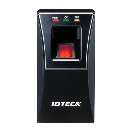
5. PRODUCT EXPLANATION 5.1 PANEL LAYOUT Status LED Fingerprint Scanner Proximity Reader Speaker (Figure: Panel Codes) 5.2 CONNECTION LAYOUT Tamper SW CON-4 CON-3 CON-2 DIP SW CON-1 (Figure: Connecter Arrangement) -
Page 11: Color Coded & Wiring Table
5.3 COLOR CODED & WIRING TABLE I/O PORT NAME SIGNAL NAME WIRE COLOR CON-1: Power (2PIN Connector) Power (+12V) DC +12V Ground GND (-) Black CON-2: In/Output (6PIN Connector) EX-DATA0 EX Input Wiegand DATA0 Pink ABA Track II Data In EX-DATA1 EX Input Wiegand DATA1 Cyan... -
Page 12: Installation Tips & Check Points
6. INSTALLATION TIPS & CHECK POINTS Please refer to information below to stably operate the LX006. 6.1 CHECK POINTS BEFORE INSTALLATION 6.1.1 CABLE SELECTION POWER POWER (Figure: System configuration) 6.1.2 RECOMMENDED CABLE TYPE AND PERMISSIBLE LENGTH OF CABLE Cable Maximum... -
Page 13: Check Points During Installation
GND wire and no voltage drop between ends of GND wire. (Figure: When Sharing a Single Power Supply for Multiple Units) POWER (Figure: When Using a Separate Power Supply for the LX006) 6.2 CHECK POINTS DURING INSTALLATION 6.2.1 TERMINATION RESISTOR Termination resistors are used to match impedance of the network to the impedance of the transmission line being used. -
Page 14: How To Connect Termination Resistors
If you do not find both earth ground and chassis ground, then connect one end of shield wire to power ground. (GND of LX006). Note that if the chassis ground is not properly connected to the earth and floated from the ground level, then grounding to the chassis ground will make the worst communication;... -
Page 15: Installation Of The Product
- Drill a hole in the center of the Wall Mount for cable. - Take out the cable from the center of hole. - Wire cable to four connecters and then perform initialization and set communication ID. - By using of one screw on the bottom, fix the Wall Mount with LX006. -
Page 16: System Initialization
6. You must specify the communication address and register the master ID. Cautions • After fixing the LX006 on the wall mount, you can’t initialize the system by this procedure. But you can initialize it through Application Software • If you initialize the system using software, all data except for the IP setting returns to the default. -
Page 17: Communication Id Setting
ID on the same communication loop must not be duplicated. There is 8-bit DIP switch on the back of LX006 for communication ID setting and each channel of DIP switch has assigned address values. The communication ID is calculated by the sum value of each bit set to “ON”... -
Page 18: Wiring
1. Connect +12V (+) wire of Power to Red wire of LX006 2. Connect GND (-) wire of Power to Black wire of LX006 Cautions You can use separate power supplies for the LX006 and the Controller; however, the GND(-) wire must be connected to the Black wire, in any case. -
Page 19: Input Wiring
7.5.3 INPUT WIRING External LED Control Connection Connect the LED Control Input wire (Blue wire with White stripe) to the NO port of controller relay output, and GND to the COM port. Set I/O of the controller; then you can control tuning on and off the green LED. -
Page 20: Output Connection
2. Connect Wiegand Data 1 wire (White wire) to Wiegand Data 1 terminal of the Controller. (Used for CLOCK when ABA Track II is output) 3. The GND(-) wire must be connected between the LX006 and the Controller. Access Error Signal Connection - Connect the Access Error Signal wire (Orange wire) to the Access Error Input terminal of the Controller. -
Page 21: External Reader Connection
LX006 (Pink wire). 4. Connect the Wiegand Data 1 wire of the External Reader to the Wiegand Input Data 1 wire of LX006 (Cyan wire). 5. The GND(-) wire must be connected between the external and the LX006. Compatible Reader: LX006:... -
Page 22: Communication
8.1 RS485 COMMUNICATION PORT CONNECTION 8.1.1 RS485 COMMUNICATION PORT CONNECTION (SINGLE CONNECTION) An RS-485/RS-232 converter is required to connect serial communication RS485 between the LX006 Main Unit and the Host Computer. - Connect RS485 - RTX (+) (Yellow) wire of Main Unit to RS485-A of Converter. -
Page 23: Rs485 Communication Port Connection (Multiple Connection)
- Connect RS485-B(-) (Gray) of one LX006 to RS485–B(-) (Gray) of another LX006. - Set different COMM ID for each LX006. Second, you have to connect one of RS485 port of LX006 to RS485/RS232 converter. - Connect RS485-A(+) (Yellow) of one LX006 to RS485-A port of the Converter. -
Page 24: Tcp/Ip Communication Port Connection
For TCP/IP communication, external cable is required to connect to CON4 (8PIN connecter). Please follow the following instructions. 1. Connect the LAN cable of the network system to the RJ45 jack of the LX006. 2. Install and run the Application Software. -
Page 25: Basic Setting
- Initialization should be performed before mounting the LX006 to the Wall Mount. - If you need to initialize LX006 after installing it on the wall, you can use the Application Software to do that. (Refer to the Software Manual for more information.) - For more information about how to initialize the LX006, refer to ‘7.3 SYSTEM INITIALIZATION’. -
Page 26: Operation Mode
10. OPERATION MODE 10.1 MASTER CARD REGISTRATION MODE While the LX006 is operating in the Master Card Registration Mode, the Red and Green LEDs are lit. 10.1.1 MASTER CARD REGISTRATION The card presented to the LX006 for the first time after initialization becomes the master card. - Page 27 2. Yellow and Green LED indicators blink. 3. Present the Proximity Card you want to delete to the LX006. 4-1. RF + FINGER MODE: After presenting the user card you want to register, you should enter the desired fingerprint twice.
-
Page 28: User Card Deletion
ABA Track II format.) 10.3.2 AUTHORIZATION If the LX006 is operating in the RF-Only Mode or the User Card is registered as an RF-Only mode card, 1. Present the registered card to the LX006. -
Page 29: Reader Indicator
BEEPS FAILED, PLEASE TRY AGAIN User card/Fingerprint deletion successfully ID DELETED BEEPS completed READER MODE The LX006 is in its normal status, waiting for a READER MODE User Card to be presented. 1 BEEP ACCESS GRANTED Authentication completed ACCESS DENIED,... -
Page 30: Default Settings
10.5 DEFAULT SETTINGS The initialization before installation restores the default values (factory settings) of the LX006. For desired applications, you may adjust or customize the settings via the Application Software. The default values for the basic settings are as follows;... -
Page 31: Output Format
Bit 26 / Bit 34: From Bit 14 to Bit 25 / From odd parity Bit18 to Bit 33 Output Timing 11.2 ABA TRACK Ⅱ (SELECTABLE USING THE SOFTWARE) Data format Zero bit ID number (00000~65535) Facility Code (00000~00255)-LX006 (00000~65535)-LX006SR Low bit first, odd parity last Start Character (11010 Hex ‘B’) Zero bit (10bit) -
Page 32: Output Mode
Output timing 1240us 940us (RD1) 6000us Data 6000us 1544us (RD0) 11.3 OUTPUT MODE 11.3.1 NORMAL OUTPUT MODE User ID / Fingerprint authorized User ID unregistered/ Fingerprint error... -
Page 33: Extension Output Mode (Set By Application Software)
2. Initialize the unit referring to user’s manual. (When this problem occurs before mounting the LX006 on the wall) Cause * You can use application software for initialization if the LX006 is already mounted on the wall. 3. If the problem still remains after following the procedure above, contact the designated service center. - Page 34 1. Check the fingerprint position on the scanner. . Wrong position Correct position 정상적인 지문 위치가 잘못된 지문들 2. Check condition of the fingerprint. Low pressure High pressure Normal Cause 3. ADAPTIVE MODE is to compensate too dry and wet fingerprint. When ADAPTIVE MODE is applied, the fingerprint capture time takes longer but the performance of fingerprint recognition will be higher.
- Page 35 2. Check the line connection for communication. In case of RS485 RS485 (mono) RS485/232 LX006 Converter RS485-A(+) RS485-A(+) RS232 Cable of connecter RS485-B(-) RS485-B(-) RS485(Multi Drop) RS485/232 LX006 LX006 Converter RS485-A(+) RS485-A(+) RS485-A(+) RS232 Cable of connecter RS485-B(-) RS485-B(-) RS485-B(-) - When a multi-drop communication doesn’t work, test one-by-one...
- Page 36 B. How to register fingerprint Correct Fingerprint Registration Method Correct Method Scanning Successful Fingerprint Verification / Identification Incorrect Method Scanning Fail Fingerprint Verification / Identification In case of not a fingerprint registration Wet Fingerprint Dry Fingerprint Scarred Fingerprint Injured Fingerprint Scarred Management Method If Fingerprint is excellently recognized...
-
Page 37: Fcc Registration Information
13. FCC REGISTRATION INFORMATION FCC Requirements Part 15 CAUTION: Any changes or modifications in construction of this device which are not expressly approved by the responsible for compliance could void the user's authority to operate the equipment. NOTE: This device complies with Part 15 of the FCC rules. Operation is subject to the following two conditions;... -
Page 38: Warranty Policy And Limitation Of Liability
This Limited Warranty is in lieu of all other warranties, obligations, or liabilities on the part of IDTECK, and IDTECK DISCLAIMS ANY AND ALL WARRANTY, WHETHER EXPRESS OR IMPLIED, OF MERCHANTABILITY OR FITNESS FOR A PARTICULAR PURPOSE.IDTECK does not, and cannot,... -
Page 39: How To Make Rma Request (After Sales Service)
(Please refer to the IDTECK webpage for more details.) 2. RMA Code will be issued after the RMA Center reviews the RMA request form. 3. Enclose the product along with the RMA Code and send it to IDTECK RMA Center. (Product without RMA Code is not accepted.) If you have any questions or problems regarding the RMA services, please contact us using the contact information below. - Page 40 The specifications contained in this manual are subject to change without notice. 5F, Ace Techno Tower B/D, 684-1, Deungchon-Dong, Gangseo-Gu, Seoul, 157-030, Korea Tel : +82-2-2659-0055 Fax : +82-2-2659-0086 E-mail : webmaster@idteck.com Copyright © IDTECK Co., Ltd.
Need help?
Do you have a question about the LX006 and is the answer not in the manual?
Questions and answers