Table of Contents
Advertisement
Quick Links
Advertisement
Table of Contents
Troubleshooting

Subscribe to Our Youtube Channel
Related Manuals for IDTECK LX006

Summary of Contents for IDTECK LX006
-
Page 2: Table Of Contents
Table of Contents ............Table of Contents . - Page 3 .. 26 2.2 RS485 COMMUNICATION PORT CONNECTION (MULTIPLE CONNECTION) First, you have to connect all RS485 port of all LX006/SRs in parallel. (Maximum of 255) Second, you have to connect one of RS485 port of LX006/SR to RS485/RS232 converter........ 27 3 TCP/IP COMMUNICATION PORT CONNECTION .
- Page 4 3.1 READER MODE FUNCTION............ 34 3.2 AUTHORIZATION If the LX006/SR is operating in the RF-Only Mode or the User Card is registered as an RF ............ 34 -Only mode card, If the LX006/SR is operating in the RF+FINGER Mode and the User Card is registered as .......... 34...
- Page 5 ........ 47 In the case of RS485 communication ....... 47 4.2 Please check if the communication ID is good.... 47 Check communication address setting of software and the device...... 48 4.3 Please check if the communication port setting is good...... 48 5 I want to access with card only, without fingerprint.
-
Page 6: Safety Information
Safety Information CAUTION: TO REDUCE THE RISK OF ELECTRIC SHOCK, DO NOT REMOVE COVER (OR BACK) NO USER SERVICEABLE PARTS INSIDE. REFER SERVICING TO QUALIFIE D SERVICE PERSONNEL. This symbol indicates that dangerous voltage consisting a risk of electric shock is pres ent within this unit. - Page 7 3. Do not connect multiple controllers to a single adapter. Exceeding the capacity may cau se abnormal heat generation or fire. 4. Securely plug the power cord into the power receptacle. Insecure connection may caus e fire. 5. When installing the controller, fasten it securely and firmly. The fall of controller may ca use personal injury.
-
Page 8: Important Safety Instructions
IMPORTANT SAFETY INSTRUCTIONS 1. Read these instructions. 2. Keep these instructions. 3. Heed all warnings. 4. Follow all instructions. 5. Do not use this apparatus near water. 6. Clean only with dry cloth. 7. Do not block any ventilation openings. Install in accordance with the manufacturer’s ins tructions. -
Page 9: Features
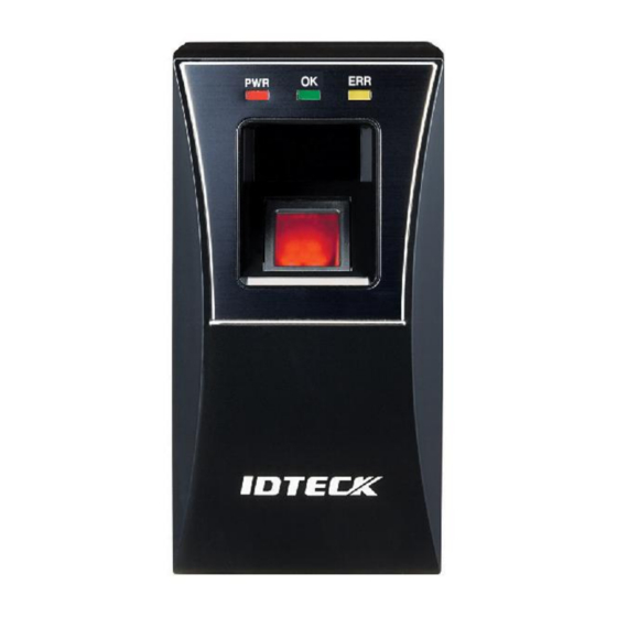
The LX006/SR is a Fingerprint and Proximity Reader compatible with existing proximit y readers. The LX006/SR has a built-in proximity reader and fingerprint module so tha t the access is only allowed when the personal ID and fingerprint are authorized and t his integrated system gives you high and reliable security. - Page 10 User Registration and Deletion Using Master Card User can register and delete IDs using Master Card without application software. Also the master card is used to toggle the LX006/SR between the reader mode and the reg istration/deletion mode. Firmware Upgrade...
-
Page 11: Specification
SPECIFICATION Model LX006 LX006SR 32bit ARM9 and Dual 8bit Micropro 32bit ARM9 and 8bit M cessor icroprocessor 2MByte Flash Memory for 1000 Fingerprints Memor Fingerprin Program Me 6MByte for 2000/4000 Fingerprints t Module mory 8MByte SDRAM Data Memor 128KByte Flash Memory... - Page 12 Certification English(Default), Language (Other Language Support Available) Read Range ● Model IDC80 IDC170 Maximum of 4 inches Read Range LX006 (10cm) Model ISC80 IHC80 Maximum of 4 inches Maximum of 2 inches (5cm) Read Range LX006SR (10cm) Fingerprint Module Specification ●...
- Page 13 High Quality optical Sensor Scanner 0.001% FAR(False Acceptance Ratio) 0.1% FRR(False Reject Ratio) ±8KV ESD(Electro Static Discharge) Less than 1sec. Verification Time Less than 2sec. Identification Time...
-
Page 14: Identifyng Supplied Parts
IDENTIFYNG SUPPLIED PARTS Please unpack and check the contents of the box. If any of flowing items is missing, please c ontact nearby contributor. (Optional accessories, if purchased, may be included in the packa ge.) -
Page 15: Product Explanation
PRODUCT EXPLANATION PANEL LAYOUT p.10... -
Page 16: Connection Layout
CONNECTION LAYOUT COLOR CODED & WIRING TABLE I/O PORT NAME SIGNAL NAME WIRE COLOR CON-1: Power (2PIN Connector) Power (+12V) DC +12V Ground GND (-) Black CON-2: In/Output (6PIN Connector) EX Input Wiegand DATA0 EX-DATA0 Pink ABA Track II Data I EX Input Wiegand DATA1 EX-DATA1 Cyan... - Page 17 RS485 RS485-A(+) RS485-A(+) Yellow RS485-B(-) RS485-B(-) Gray CON-3: In/Output (8PIN Connector) Wiegand DATA 0 DATA-0 Green ABA Track II Data Wiegand DATA 1 DATA-1 White ABA Track II Clock ERROR SIGNAL OUT ERROR SIGNAL O Orange ABA Track II CLS OK SIGNAL OUT OK SIGNAL OUT Orange with Black...
-
Page 18: Installation Tips & Check Points
INSTALLATION TIPS & CHECK POINTS Please refer to information below to stably operate the LX006/SR. CHECK POINTS BEFORE INSTALLATION CABLE SELECTION p.13... -
Page 19: Recommended Cable Type And Permissible Length Of Cable
RECOMMENDED CABLE TYPE AND PERMISSIBLE LENGTH OF CABLE Description Cable specification Maximum dist ance LX006/SR Power (DC+12V)DC Power -> LX006 Belden #9409,18 AW 2 conductor, unshiel RS232 Cable converter->Host P.C. Belden #9829, 24 A 2-twisted pair, shield RS485 CableLX006 -> LX006LX006 -> Convert... -
Page 20: Check Points During Installation
Disconnect +12V wire from the ACU and connect external power supply to the rea der nearby. There will be no current flow through the GND wire and no voltage dr op between ends of GND wire. CHECK POINTS DURING INSTALLATION TERMINATION RESISTOR Termination resistors are used to match impedance of the network to the impedance of the transmission line being used. -
Page 21: How To Connect Termination Resistors
If you do not find both earth ground and chassis ground, then connect one end of shield wir e to power ground. (GND of LX006/SR). Note that if the chassis ground is not properly connected to the earth and floated from the ground level, then grounding to the chassis ground will make the worst communication;... -
Page 22: Installation Of The Product
INSTALLATION OF THE PRODUCT WALL MOUNT DRAWING p.17... -
Page 23: Installation Of Wall Mount
● Wire cable to four connecters and then perform initialization and set communication ID. ● By using of one screw on the bottom, fix the Wall Mount with LX006/SR. ● SYSTEM INITIALIZATION Initialize the system using the DIP switch on the rear of the product. -
Page 24: Communication Id Setting
6/SR in the software so each communication ID on the same communication loop must not be duplicated. There is 8-bit DIP switch on the back of LX006/SR for communication ID setting and each ch annel of DIP switch has assigned address values. The communication ID is calculated by the s um value of each bit set to “ON”... -
Page 25: Wiring
WIRING WIRING LAYOUT Power Wiring 1. Connect +12V (+) wire of Power to Red wire of LX006/SR 2. Connect GND (-) wire of Power to Black wire of LX006/SR WIRING p.20... -
Page 26: Input Wiring
You can use separate power supplies for the LX006/SR and the Controller; howeve r, the GND(-) wire must be connected to the Black wire, in any case. INPUT WIRING External LED Control Connection Connect the LED Control Input wire (Blue wire with White stripe) to the NO port of controlle r relay output, and GND to the COM port. -
Page 27: Output Connection
OUTPUT CONNECTION WIRING p.22... -
Page 28: Wiegand Data Output Connection
2. Connect Wiegand Data 1 wire (White wire) to Wiegand Data 1 terminal of the Controll (Used for CLOCK when ABA Track II is output) 3. The GND(-) wire must be connected between the LX006/SR and the Controller. Access Error Signal Connection Connect the Access Error Signal wire (Orange wire) to the Access Error Input terminal of the Controller. -
Page 29: External Reader Connection
LX006/SR (Pink wire). 4. Connect the Wiegand Data 1 wire of the External Reader to the Wiegand Input Data 1 wire of LX006/SR (Cyan wire). 5. The GND(-) wire must be connected between the external and the LX006/SR. Compatible Reader: LX006... -
Page 30: Communication
COMMUNICATION RS232 COMMUNICATION PORT CONNECTION For RS232 communication, you should use an external RS232 serial cable. 1. Connect the RS232 serial cable between the stereo jack plug on the bottom of the LX0 06/SR and the COM1 or COM2 port of the Host Computer. 2. -
Page 31: Rs485 Communication Port Connection (Multiple Connection)
RS485/RS232 converter is required to use RS485 communication between multiple LX006/S Rs and a host computer. Please follow the following instructions. First, you have to connect all RS485 port of all LX006/SRs in parallel. (Maximum of 255) 1. Connect RS485-A(+) (Yellow) of one LX006/SR to RS485–A(+) (Yellow) of another LX0 06/SR. -
Page 32: Second, You Have To Connect One Of Rs485 Port Of Lx006/Sr To Rs485/Rs232 Converter
For TCP/IP communication, external cable is required to connect to CON4 (8PIN connecter). Please follow the following instructions. 1. Connect the LAN cable of the network system to the RJ45 jack of the LX006/SR. 2. Install and run the Application Software. - Page 33 TCP/IP COMMUNICATION PORT CONNECTION p.28...
-
Page 34: Basic Setting
Initialization should be performed before mounting the LX006/SR to the Wall Mount. ● If you need to initialize LX006/SR after installing it on the wall, you can use the Applicati ● on Software to do that. (Refer to the Software Manual for more information.) For more information about how to initialize the LX006, refer to ‘7.3 SYSTEM INITIALIZA... - Page 35 ted by the sum value of each switch set to “ON” position. Communication ID can be set f rom ‘000’ to ‘255’. Please refer to the ‘7.4 COMMUNICATION ID SETTING’ for more detai COMMUNICATION ID SETTING p.30...
-
Page 36: Operation Mode
OPERATION MODE MASTER CARD REGISTRATION MODE While the LX006/SR is operating in the Master Card Registration Mode, the Red and Green LEDs are lit. MASTER CARD REGISTRATION The card presented to the LX006/SR for the first time after initialization becomes the master card. -
Page 37: Master Card Function
MASTER CARD FUNCTION. The Master Card is used to toggle the LX006/SR between the Reader Mode and the Registra tion Mode. For example, If you present the master card in the Reader Mode, the LX006/SR shifts to the Regi stration Mode. -
Page 38: User Card Deletion
- Present the proximity card to the LX006/SR. - Place the fingerprint on the fingerprint scanner while red light is illuminated from - Lift the fingerprint up when the red light from the scanner turns off. - Place the fingerprint on the fingerprint scanner once again while the red light is il luminated again. -
Page 39: Reader Mode
(The error signal is not generated when using ABA Track II format.) AUTHORIZATION If the LX006/SR is operating in the RF-Only Mode or the User Card is registered as a n RF-Only mode card, 1. Present the registered card to the LX006/SR. -
Page 40: If The Card Hasn't Yet Been Registered
Signal output (Low Active) will be generated for 500ms. (The error signal is not generat ed when using ABA Track II format.) READER INDICATOR BEEP VOICE ME STATUS SSAGE WELCOM Power is applied and the LX006/SR is booting up. E TO ACES CONTROL SYSTEM SYSTEM I The initialization has been finished. NITIALIZE REGISTRATION MODE MASTER I In the status of system initialize. -
Page 41: Default Settings
EASE TRY AGAIN 4 BEEPS ID DELETE User card/Fingerprint deletion successfully completed READER MODE READER The LX006/SR is in its normal status, waiting for a User MODE Card to be presented. 1 BEEP ACCESS G Authentication completed RANTED 2 BEEPS... - Page 42 The initialization before installation restores the default values (factory settings) of the LX00 6/SR. For desired applications, you may adjust or customize the settings via the Application Software. The default values for the basic settings are as follows; 1. Operating Mode: RF + FINGER 2.
-
Page 43: Output Format
OUTPUT FORMAT WIEGAND OUTPUT (DEFAULT) Data format (26-bit /34-bit(SR)) Bit 1 / Bit 1: From Bit 2 to Bit 13 / From even parity Bit 2 to Bit 17 Bit 2 to Bit25 / Bit 2 to Bit33: 3-byte ID number / 4-byte ID number Bit 26 / Bit 34: From Bit 14 to Bit 25 / From odd parity Bit18 to Bit 33 Output Timing p.38... -
Page 44: Aba Track Ⅱ (Selectable Using The Software)
ABA TRACK Ⅱ (SELECTABLE USING THE SOFTWARE) Data format Output timing OUTPUT MODE p.39 OUTPUT FORMAT... -
Page 45: Normal Output Mode
NORMAL OUTPUT MODE EXTENSION OUTPUT MODE (SET BY APPLICATION SOFTWARE) OUTPUT MODE p.40... -
Page 46: Appendix
2. Initialize the unit referring to user’s manual. (When this problem occurs before mounting the LX006/SR on the wall) You can use application software for initialization if the LX006/SR is a ● lready mounted on the wall. 3. If the problem still remains after following the procedure above, contact the designated service center. - Page 47 2. Check condition of the fingerprint. 3. ADAPTIVE MODE is to compensate too dry and wet fingerprint. When A DAPTIVE MODE is applied, the fingerprint capture time takes longer but th e performance of fingerprint recognition will be higher. You can apply ADAPTIVE MODE using application software. ☞...
- Page 48 Parity bit : NONE Data bit : 8bit Stop bit : 1bit In case of using TCP/IP Communication - Check IP, Subnet Mask, Gateway and Port setting value. - Check more information about above setting value using the software m anual.
-
Page 49: How To Register Fingerprint
How to register fingerprint How to register fingerprint p.44... -
Page 50: Troubleshooting
Troubleshooting Before requesting RMA, please check the cases below if your problem is one of them. 1 IDs have been transmitted from software to the device, but I cannot access. 2 The device does not go to setting mode after reading MASTER ID. 3 A buzzer keeps making sounds. -
Page 51: The Device Does Not Go To Setting Mode After Reading Master Id
If the problem persists, please contact service center. The device does not go to setting mode after reading MASTER ID. MASTER ID may have changed. 1. Change MASTER ID using software. 2. If you cannot change it using software, see 3. -
Page 52: The Device Dose Not Communicate With Pc
The device dose not communicate with PC. Please check wiring. See [Communication] of the manual and check if the wiring is good. In the case of RS232 communication See [Communication] > [RS232 Communication Port Connection] of the manual and check i f the wiring is good. -
Page 53: Please Check If The Communication Port Setting Is Good
ddress set in the device. 2. When you use several devices together, communication addresses set in the devices sh ould be different from each other. 3. Check if baud rate is same with baud rate set in a software. * If you initialize the device, baud rate is set to 57,600 bps which is the default. Please check if the communication port setting is good. -
Page 54: Want To Access With Fingerprint Only, Without Card
If the problem persists, please contact service center. I want to access with fingerprint only, without card. Please check if IDENTIFICATION mode is set to "USE". Set IDENTIFICATION mode to "USE" from software. If the problem persists, please contact service center. A fingerprint is not recognized. -
Page 55: Want To Register 2 Fingerprints For 1 Id
If the problem persists, please contact service center. I want to register 2 fingerprints for 1 ID. Please check if Dual Fingerprint Mode is set to "USE". If you use Dual Fingerprint Mode, you can register 2 fingerprints for 1 ID just in case a finger print is injured. -
Page 56: Fcc Registration Information
FCC REGISTRATION INFORMATION FCC Requirements Part 15 Caution: Any changes or modifications in construction of this device which are not expressly approved by the responsible for compliance could void the user's authority to operate the e quipment. NOTE: This device complies with Part 15 of the FCC rules. Operation is subject to the following two conditions;... -
Page 57: Rma Request
RMA Request If you have any questions or problems regarding the RMA services, please contact us using t he contact information below. Friendly representatives at IDTECK are always standing by to provide the best after sales services. IDTECK Headquarter 5F, Ace Techno Tower B/D, 684-1, Deungchon-Dong,...
Need help?
Do you have a question about the LX006 and is the answer not in the manual?
Questions and answers