Table of Contents
Advertisement
Advertisement
Table of Contents
Troubleshooting

Subscribe to Our Youtube Channel
Related Manuals for ASCOM Elise3 Lite


Summary of Contents for ASCOM Elise3 Lite
-
Page 1: Installation Guide
TD 92679EN Installation Guide Elise3 22 November 2013 / Ver. G... - Page 2 Use this product only in accordance with the purposes for which it is designed. For the latest version of all Ascom documentation, contact your local supplier or visit the Ascom Partner Website at https://www.ascom-ws.com...
- Page 3 EMC Directive 2004/1 08/EC, LVD Directive 2006/95/EC, Eco Design 2005/32/EC, and RoHS Directive 2011/65/EU. The Declaration of Conformity may be consulted at: http://www.ascom-ws.com/doc/ Safety Compliance Regulatory Compliance The equipment described herein complies with: (US/CAN) •...
- Page 4 Installation Guide TD 92679EN Elise3 Information to user This device complies with Part 15 of the FCC Rules. Operation is subject to the following two conditions: i) this device may not cause harmful interference, and ii) this device must accept any interference received, including interference that may cause undesired operation.
-
Page 5: About This Document
Installation Guide TD 92679EN Elise3 About this document This document is used for installation and configuration of the Elise3, as well as for administration and troubleshooting. Target groups • The field engineer that installs, maintains and troubleshoots the system • The system administrator responsible for the IT management at the customer site, that needs to get error messages, to survey and have control of the system. -
Page 6: Table Of Contents
Installation Guide TD 92679EN Contents 1. Introduction ........................1 1.1 Abbreviations and Glossary ..................2 2. General Information...................... 3 2.1 Licenses ........................3 2.2 MAC Address ......................3 2.3 Authentication and Administration ................ 3 3. Description ........................5 3.1 Overview of Connectors, Buttons and LEDs ............5 3.2 Label for IP Address/Host Name ................ -
Page 7: Introduction
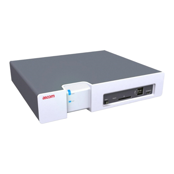
Elise3 comes in different variants; Elise3 Lite, Elise3 Standard, Elise3 LON/ISC and Elise3 LON/NSS. The Elise3 Lite is intended for connections via IP only. It has two LAN connections, two USB 2.0 ports for communication with external devices, one mini-USB port for easy management and is equipped with two galvanically isolated physical inputs and outputs. -
Page 8: Abbreviations And Glossary
Installation Guide 1. Introduction TD 92679EN Elise3 Tools etc. required: Philips screwdriver (Ph No. 2) for the wall screws size 3.5×40 mm (0.14×1.6 in) Torx (T10) for the MFT screws size M3×6 mm (0.12 × 0.24 in) Screwdriver 0.40×2.5 mm (0.16×0.098 in) for screw connectors on the rear side Ethernet cable System Bus Cabling... -
Page 9: General Information
• in the product’s Setup Wizard • in the product’s Configuration page • in the product’s Advanced Configuration page New licenses can be downloaded from the Ascom extranet (https://www.ascom-ws.com). MAC Address The MAC address can be found: • on a label on the hardware’s rear side •... - Page 10 Installation Guide 2. General Information TD 92679EN Elise3 2.3.2 Administration The Advanced Configuration page requires the sysadmin/admin account. The page can be reached directly by entering “xxx.xxx.xxx.xxx/admin” in a web browser, where xxx.xxx.xxx.xxx is the product’s IP address. The Advanced Configuration page can also be accessed by clicking the “Configuration”...
-
Page 11: Description
Installation Guide 3. Description TD 92679EN Elise3 Description The Elise3 front side has different status indications and is used for maintenance. The LEDs indicate the status of the product and the management port makes it possible to have direct connection to the product. It also has an SD card slot and two USB ports for use with external temporary devices. - Page 12 LAN 2 is currently not used (for future releases) S900 connections (A-bus) Modular jacks (RJ45) used for connection of Ascom Paging System, Output modules, and Alarm Modules with modular system bus cabling. Not applicable for the Elise3 Lite version.
-
Page 13: Label For Ip Address/Host Name
Installation Guide 3. Description TD 92679EN Elise3 100-240 Vac Used for connection of supply voltage. Label for IP Address/Host Name To facilitate future support and access to the module, the product’s IP address or Host name can be printed on a blank label and attached as shown in figure The blank label is found on the back side of the Getting started document: “Elise3 –... -
Page 14: Operating Mode
Installation Guide 3. Description TD 92679EN Elise3 Flashing patterns Figure 4. LED indications Status LED Status OK Blue Starting up/shutting down Blue Feedback (1 sec.) Blue Error/fault Mode LED Warning Boot mode Yellow Blue Power LED Demonstation mode Yellow Blue Active module during Blue synchronization... - Page 15 Installation Guide 3. Description TD 92679EN Elise3 3.4.3 Demonstration Mode Demonstration Mode makes it possible to run the Elise3’s software for two hours with full or almost full functionality, with or without a valid license. Exact functionality is software dependent. For more information about the functionality during demonstration mode, see the product’s documentation.
-
Page 16: Installation And Configuration
Installation Guide 4. Installation and Configuration TD 92679EN Elise3 Installation and Configuration The Elise3 can be mounted vertically on a wall or be placed horizontally in a 19” rack. It must be fixed by screws or other fixtures to the wall or rack, and must not be easily movable. Figure 5. - Page 17 Installation Guide 4. Installation and Configuration TD 92679EN Elise3 Figure 6. Mounting on a wall Connectors Connectors 4.1.4 Rack Mounting The Elise3 can be either front mounted or reverse mounted in a 19” rack. Accessories for mounting in a rack (ordered separately). Item No.
- Page 18 Installation Guide 4. Installation and Configuration TD 92679EN Elise3 Fasten the big assembly bracket on the right side of the Elise3 and the small assembly brackets on the left side, as shown in the figure below. Fasten the assembly brackets in the rack as shown in the figure below (screws not included).
- Page 19 Installation Guide 4. Installation and Configuration TD 92679EN Elise3 Use the two small standard assembly brackets and fasten one on the right front side and the other on the left front side. Fasten the assembly brackets in the rack as shown in figure below (screws not included).
- Page 20 Installation Guide 4. Installation and Configuration TD 92679EN Elise3 Fasten the assembly brackets in the rack as shown in the figure below (screws not included). Rear mounted double Rear mounting of double Elise3 require the reverse 19” rack kit. Use the supplied assembly brackets and mount the two Elise3 together, both on the rear side and on the bottom side as shown in figure below.
-
Page 21: Supply Voltage
Installation Guide 4. Installation and Configuration TD 92679EN Elise3 Supply Voltage The Elise3 can be connected to an external power supply (12-24 Vdc battery or power source) as a complement to the primary power supply (100-240 Vac). If the primary power supply fails it switches over to the external power supply automatically, without any negative influence on the running application. -
Page 22: Connections
4.3.2 S900/A-bus connection The Elise3 can be connected to Ascom Paging System, Alarm modules, and Output modules; either via modular system bus cabling or via twisted-pair lines to 1 and 2 on screw connector A-bus. - Page 23 Installation Guide 4. Installation and Configuration TD 92679EN Elise3 Elise3 can be connected to teleCARE M equipment. Connections are made with twisted pairs to 1 and 2 on screw connector LON. Figure 8. LON connector on Elise3. A-bus 4.3.4 Error Relay Output A relay output is used to indicate Elise3 malfunction and to indicate errors.
- Page 24 Installation Guide 4. Installation and Configuration TD 92679EN Elise3 Galvanic isolation of the inputs and outputs is provided by using a separate power supply, figure Figure 10. Example of AUX output with galvanic isolation. +V In In Out Out GND Error Ext 1 2 Ext...
-
Page 25: Strain Reliefs And Warning Labels For Medical Devices
Elise3 Strain Reliefs and Warning Labels for Medical Devices For medical device gateways such as Ascom Cardiomax, Ascom Mobile Monitoring Gateway (MMG), and for installations requiring seismic considerations; cable strain reliefs and warning labels must be used. Cable ties, anchors, 8 mm (0.31 in) screws, and warning labels are included in the delivery in a separate package (Item. -
Page 26: 4.5 Accessing Elise3
Installation Guide 4. Installation and Configuration TD 92679EN Elise3 Figure 14. Cable ties on the network cable side Put a warning label on the top side of Elise3, and put warning labels on the cables close to the wall socket as shown in the figures below. Figure 15. - Page 27 Installation Guide 4. Installation and Configuration TD 92679EN Elise3 4.5.1 Access via Network It is recommended that the Elise3 always gets the same IP address if it communicates with other equipment, to prevent it from losing contact with the equipment after a restart. Inform the network administrator about the MAC address and ask to reserve a fixed IP address via DHCP for this Elise3.
- Page 28 Installation Guide 4. Installation and Configuration TD 92679EN Elise3 Enter the IP address “192.5.36.229" in a web browser on your computer to access the product’s web interface. Continue in 4.6 Basic Configuration on page 24. Install the Port Driver on Windows XP/Vista NOTE: When switching between mass storage mode and network mode, it takes about 30 seconds before the Elise3 can be accessed with the 192.5.36.229 address.
- Page 29 Installation Guide 4. Installation and Configuration TD 92679EN Elise3 Install the Port Driver on Windows 7 NOTE: When switching between mass storage mode and network mode, it takes about 30 seconds before the Elise3 can be accessed with the 192.5.36.229 address. Connect a mini-USB type B cable between the USB port on your computer and the management port on the Elise3.
-
Page 30: Basic Configuration
Installation Guide 4. Installation and Configuration TD 92679EN Elise3 Browse to the folder where the port driver is saved and click “Next”. A Windows security window opens. Click “Install this driver software anyway”. The installation of the port driver begins. Click “Close”... - Page 31 Installation Guide 4. Installation and Configuration TD 92679EN Elise3 Enter user name “admin” and the password “changeme”. Click “System Setup” and navigate to “Network”. Set the network parameters. Click “License” and enter the license number. Set the time, see 4.6.4 Clock Synchronization and Time Settings on page 25 Change the default passwords for all users.
- Page 32 Installation Guide 4. Installation and Configuration TD 92679EN Elise3 4.6.5 Message Distribution In the administration pages, there are distribution lists that are used to distribute incoming information. The internal distribution is automatically set, but external distribution of incoming data has to be configured separately. Distribution of “Status Logs”...
-
Page 33: Working In Boot Mode
Installation Guide 5. Working in Boot Mode TD 92679EN Elise3 Working in Boot Mode If the software installed on the Elise3 cannot be started, the Boot Mode can be used for installing new software, see settings, performing factory reset, troubleshooting and also starting up in normal operation again. - Page 34 Installation Guide 5. Working in Boot Mode TD 92679EN Elise3 5.1.2 Network Settings Under System > Network the network settings are shown. All network settings can be edited in this view if DHCP is disabled, but only the Host name if DHCP is enabled. Figure 19.
- Page 35 Installation Guide 5. Working in Boot Mode TD 92679EN Elise3 Click the “Browse...” and locate the software (.pkg) file to install. Select where to save the software. If two versions of the software already have been installed on the module choose which software to replace. Select if the Elise3 shall be restarted after the installation or not.
-
Page 36: Demonstration Mode
Installation Guide 6. Demonstration Mode TD 92679EN Elise3 Demonstration Mode The Demonstration Mode can be set when the module is running in normal operation, either via the product’s web interface or manually by using the Mode button. Press and hold the Mode button for 10 seconds. Demonstration Mode is indicated by the Status LED with slow flashing yellow light and by the Mode button LED with fixed blue light The module will automatically return to the previous license and parameters (without... -
Page 37: Maintenance
Installation Guide 7. Maintenance TD 92679EN Elise3 Maintenance Software Management 7.1.1 Installation of Software Normally the installation of software is done from the product’s web interface but it can also be done in Boot Mode, see 5.1.3 Install Software in Boot Mode on page 28. -
Page 38: Restarting The Elise3
Installation Guide 7. Maintenance TD 92679EN Elise3 Restarting the Elise3 7.2.1 Controlled Restart using Restart Button When a controlled restart is performed via the Restart button, all ongoing jobs on the Elise3 ends in a controlled way and everything is logged. When the Elise3 has shut down, the user can unplug the power cable or wait one minute for the Elise3 to automatically start up again. -
Page 39: Troubleshooting
Installation Guide 8. Troubleshooting TD 92679EN Elise3 Troubleshooting Troubleshooting is normally done by accessing the product’s web interface to see logs, statistics etc. But if for some reason the application's web interface cannot be reached, it is possible to get access to the information by placing the product in Troubleshoot mode. See 8.1 Troubleshooting from Boot Mode on page 34 Fault... -
Page 40: Troubleshooting From Boot Mode
Installation Guide 8. Troubleshooting TD 92679EN Elise3 Troubleshooting from Boot Mode Via the Troubleshoot button in the Boot Mode GUI, you get access to the product’s web interface (no applications are running) and will be able to see logs and other information. When troubleshooting, it is always a good idea to examine the log files, since they provide additional information that may prove useful. -
Page 41: Related Documents
Installation Guide 9. Related Documents TD 92679EN Elise3 Related Documents Configuration Manual, Unite Connectivity Manager TD 92735EN Configuration Manual, IMS3 TD 92962EN Installation and Operation Manual, MMG TD 92654GB Installation and Operation Manual, Cardiomax TD 92901EN 22 November 2013 / Ver. G... -
Page 42: 10. Document History
Installation Guide 10. Document History TD 92679EN Elise3 10. Document History For details in the latest version, see change bars in the document. Version Date Description 03 September 2010 First released version 15 September 2010 Minor updates 05 November 2010 Minor updates 12 April 2011 Updates in figure 3 on page 7. -
Page 43: Appendix A: Move License From Elise2 To Elise3
Installation Guide Appendix A: Move License from ELISE2 TD 92679EN Elise3 Appendix A: Move License from ELISE2 to Elise3 A license for a product on ELISE2 can, if the license is compatible with Elise3, be moved to Elise3 by moving the Module key from the ELISE2 module to the Elise3 module. To make it easier to differ between the Module Keys, the marking “2M”...
Need help?
Do you have a question about the Elise3 Lite and is the answer not in the manual?
Questions and answers