Table of Contents
Advertisement
S S U U N N S S T T A A R R M M A A C C H H I I N N E E R R Y Y C C O O . . , , L L T T D D
R
USER ' ' S
MANUAL
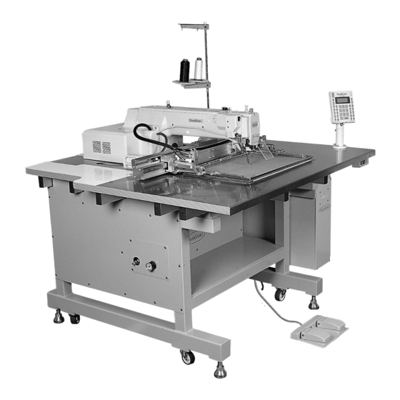
SPS/A-3020 5030 SERIES
E E l l e e c c t t r r o o n n i i c c a a l l l l y y C C o o n n t t r r o o l l l l e e d d
P P a a t t t t e e r r n n S S e e w w i i n n g g M M a a c c h h i i n n e e
1) FOR AT MOST USE WITH EASINESS,
PLEASE CERTAINLY READ THIS MANUAL
BEFORE STARTING USE.
2) KEEP THIS MANUAL IN SAFE PLACE
FOR REFERENCE WHEN THE MACHINE
BREAKS DOWN.
MME-050228
Advertisement
Table of Contents

Related Manuals for SunStar SPS/A-3020 5030 SERIES


Summary of Contents for SunStar SPS/A-3020 5030 SERIES
- Page 1 MANUAL SPS/A-3020 5030 SERIES E E l l e e c c t t r r o o n n i i c c a a l l l l y y C C o o n n t t r r o o l l l l e e d d...
- Page 2 1. Thank you for purchasing our product. Based on the rich expertise and experience accumulated in industrial sewing machine production, SUNSTAR will manufacture industrial sewing machines, which deliver more diverse functions, high performance, powerful operation, enhanced durability, and more sophisticated design to meet a number of user’s needs.
- Page 3 Organization of the SPS/A-Series Model S P S / A - 5 0 3 0 - H S Series Stitch Type Material Sewing Area(X×Y) Type 5030:500mm×300mm 3020:300mm×200mm Application G:General Material H:Heavy Material Stitch S:Standard Stitch P:Perfect Stich...
-
Page 4: Table Of Contents
CONTENT 1. Machine Safety Regulations 2. Machine Specifications 3. Machine Specifications 1) Names of Earch Part of the machine 2) Inside Structure of Control Box 4. Machine Installation 1) Machine Installation Conditions 2) Electric Installation Conditions 3) Assembly of Peripheral Components 5. - Page 5 5) Program Example 4 : Pattern Generation by Using the Second Origin and Pause 6) Program Example 5 : Change of Sewing Speed Within a Pattern 6-1) Changing the Sewing Speed from an Existing Pattern Data 6-2) Changing the Sewing Speed by Making New Pattern Data 7) Using the Extension/Reduction Modes 8) Using the Chain Sewing Mode 9) Checking and Deleting the Pattern Number...
-
Page 6: Machine Safety Regulations
MACHINE SAFETY REGULATIONS Safety instruction on this manual are defined as Danger, Warning and Notice. If you do not keep the instructoins, physical injury on the human body and machine damage might be occurred. : This indication should be observed definitely. If not, danger could be happen during the installation, Danger conveyance and maintenance of machines. - Page 7 1-4) Machine SPS/A-5030 Series is made to sew patterns on fabrics and other similar material for Operation manufacturing. Follow the following indications when operating the machine. ⓐ Read through this manual carefully and completely before operating the machine. ⓑ Wear the proper clothes for work. ⓒ...
- Page 8 1-6) Caution Mark Caution mark is attached on the machine for safety. When you operate the machine, observe the directions on the mark. Position Position of Warning Mark [ View from the right-front ] CAUTION 경 고 Do not operate without finger guard and safety devices.
-
Page 9: Machine Specifications
MACHINE SPECIFICATIONS Series Type SPS/A-3020 SPS/A-5030 X(Left and Right) : 300mm X(Left and Right) : 500mm Sewing Range Y(Before and After) : 200mm Y(Before and After) : 300mm Maximum Sewing Speed 2,000 spm (Stitch 3mm Shorter) Stitch 0.1 ~ 12.7mm Feed Plate Transfer Method Transfer by Stepping Pluse Motor Stroke of Needle Bar... -
Page 10: Machine Specifications
MACHINE SPECIFICATIONS 1) Names of Each Part of the Machine Emergency Stop Switch Thread Stand Body Starting Upper Feed Power ON/OFF Operation Box Control Box Table Pedal Plate Lowering Switch Pedal... -
Page 11: Inside Structure Of Control Box
2) Inside Structure of Control Box CPU+IO Board Floppy Disk Driver Main Shaft Motor Drive Board Power Board Trans Step Motor Drive Board... -
Page 12: Machine Installation
MACHINE INSTALLATION 1) Machine Installation Conditions A. Do not use the machine where the voltage is over regular voltage ±10% to prevent accidents. B. Check the indicated pressure of the devices that use atmospheric pressure such as the air cylinder to prevent any accidents from occurring. - Page 13 B. Fix the safety plate to face plate. (Please use after fixing it at the time of operation to prevent safety accident.) Face Plate Safety Plate [ Fig. 2 ] C. Connect the stand-type pedal plug to the control box. Stand-Type Pedal [ Fig.
- Page 14 E. Table leg holder ⓐ Place dustproof rubber ② on the bottom of level adjuster ①. ⓑ Put up by turning ⓑ level adjuster ① until caster ④ starts no load operation. ⓒ Fix the level adjuster ① by tightening nut ③...
-
Page 15: Preparation Before Using The Machine
PREPARATION BEFORE USING THE MACHINE 1) Setting the Voltage Input voltage Position of change connector of power voltage 95V~105V A. If a cover of electronically controlled pattern sewing machine is taken off, inside contents 106V~115V are as same as [Fig. 7]. 116V~125V B. -
Page 16: How To Supply Oil
2) How to Supply Oil A. Check the amount of oil left in the oil tank which is installed on the arm and supply oil sufficiently. [ Caution ] Be sure to supply oil when operating the machine for the first time or when the machine has not been used for a long time. -
Page 17: How To Install The Needle Bar
D. Open the hook cover and supply oil till the shuttle race ring is surrounded by oil. Put the hook cover back on after finishing. [ Caution ] For safety, keep the hook cover covered during operating. [ Fig. 11 ] E. -
Page 18: How To Pass Upper Thread
4) How to Pass Upper Thread A. After placing the thread take-up lever at its highest location, hang the upper thread as shown in the figure. Dependent upon needle bar thread guide, hang the thread as ① for the general and ② for heavy material. -
Page 19: How To Take The Bobbin Case On And Off
6) How to Take the Bobbin Case On and Off Hold knob ① of the bobbin case and push into the shuttle until a click sound is heard. [ Caution ] If you start operating the machine when a bobbin case is not perfectly installed, thread can be tangled or the bobbin case would come out. -
Page 20: How To Wind The Lower Thread
8) How to Wind the Lower Thread A. Insert bobbin thread winding driving shaft ② of thread winding base ① attached to top cover. B. Wind the thread located at thread winding mess ④ to bobbin to counter clockwise direction. C. -
Page 21: How To Adjust Air Pressure
11) How to Adjust Air Pressure After pulling back the adjustment handle located Adjustment Handle on the upper part of the filter adjuster attached to the body side as shown in the figure, turning to the clockwise direction, the pressure increases and turning to the counter clockwise direction, the pressure drops. -
Page 22: How To Use Pallet
13) How to Use Pallet This device is divided into 2 types according to clamping method of sewing material. Generally it is divided into Upper/Lower Clamp Device (See Figure 26) and Pallet Clamp Device (see Figure 28) for cassette work and unless particular order is made at the moment of purchase, Upper/Lower Clamp Device is attached and shipped out. - Page 23 e) Separate lower feed plate from main body. As it is the state that cut off the influx of air, separate lower feed plate after vertically pushing up the cylinder knuckle④ of lower feed plate. ④ [ Fig. 27 ] B.
-
Page 24: How To Adjust Upper Thread Holding Device
D. Replacement of Upper Feed Plate being used for cushion sewing material like bed(Option) a) This machine, unless there is separate order, is shipped with average 36mm of rise for the upper feed plate. For the sewing materials that cushioned materials are used such as bed/sofa, specification is prepared that increased grade of rise up to 70 mm for easy insertion of the working material. - Page 25 E. How to set upper thread holder in operation box a) In order to use upper thread holder, set the Parameter NO. 62 at ENABLE. - Setting Method:After turning the power on, press MODE KEY immediately. After turning the power on, press MODE <...
-
Page 26: Caution When Using The Floppy Disks
15) Caution When Using the Floppy Disks Observe the following principles thoroughly when you treat floppy disks. [ Caution ] Use the identified floopy disks after formatting when you get them in market. ⓐ Do not put floppy disks near magnetic-related materials such as television. ⓑ... -
Page 27: Basic Operational Method
BASIC OPERATIONAL METHOD 1) Name and Roles of Each Key on Operation Unit POWER LED Input of power READY LED Sewing available condition SPEED KEY Change of sewing speed ERROR LED Errors occurred LCD DISPLAY Indication of contents MODE KEY Change of working mode CODE KEY... -
Page 28: Name And Description Of Each Display Contents On General Operation Mode
2) Name and Description of Each Display Contents on General Operation Mode It is an initial screen when power is on for the first time, but display of screen can be changed according to the general sewing related parameter. N O : 0 0 0 N O R _ S E W POWER LED X S :1 0 0 %... -
Page 29: Flow Chart Of General Operation
3) Flow Chart of General Operation Power On NO:000 NOR_SEW POWER LED Indication of XS:100% general sewing READY LED YS:100% SP:2000 mode ERROR LED BC:000 PC:0000 General Sewing POWER LED NO:000 NOR_SEW XS:100% mode READY LED YS:100% SP:2000 ERROR LED BC:000 PC:0000 <<... -
Page 30: Work Flow Of Pattern Programming
4) Work Flow of Pattern Programming NO:000 NOR_SEW POWER LED General XS:100% READY LED sewing mode YS:100% SP:2000 ERROR LED BC:000 PC:0000 << Main Menu >> POWER LED 0.Initialize Is MODE key READY LED 1.Parameter Set pressed? ERROR LED 2.Program <<... -
Page 31: Operating After Reading The Patterns From Floppy Disks
5) Operating After Reading the Patterns from Floppy Disks ※ Caution : If READY LED turns on or upper feed plate is under, some keys are not available. It happened, operate the keys after lifting the upper feed plate or pressing ENTER key. -
Page 32: When A Machine Stops Operating During Sewing By The Thread Cut
7) When a Machine Stops Operating During Sewing by the Thread Cut A. You can get the screen like a figure on the right side. E r r 1 8 B. If you want to sew continuously at the same position, insert thread again, then step on the left pedal switch. -
Page 33: Applicable Operation
APPLICABLE OPERATION 1) Operating After Moving to a Random Start Point to Sew or the Second Origin It is possible to move to the sewing start point or the second origin by using direction keys in the sewing available state. To decide the moving point, whether it is the sewing start point or the second origin, set up 1) PNT_STR_POS or 2) SECND_ORG at the general sewing related parameter No. -
Page 34: Program Example 1 : Generating The Square Pattern
2) Program Example 1 : Generating the Square Pattern → (-650,300) (650,300) Move JUMP (0,0) (-650,-300) (650,-300) < < M a i n M e n u > > A. Insert a floppy disk into a floppy disk drive. 2 . P r o g r a m 3 . - Page 35 G. Move to each point of the square by using 0 0 7 : L I N E direction keys, then press PNT SET key respectively to input coordinates of each edge X : - 0 6 5 0 point. Whenever you press the PNT SET key, Y : 0 0 3 0 0 the number on screen will be increased.
-
Page 36: Program Example 2 : Generating The Circle Pattern
N. If there already exists the pattern number that P a t t e r n E x i s t ! you want to save in a floppy fisk, you can see the screen like a figure on the right side. If you O v e r W r i t e ? want to save the pattern with the same number, Y ( E N T E R ) / N ( E S C ) - Page 37 E. If you press EXE key, the machine operates J U M P N O N E pattern data, then the feed plate moves according X : 0 0 0 0 0 A N : 0 0 0 2 7 to the operated data.
-
Page 38: Program Example 3 : Generating The Double Curve Pattern
M. Press TEST key one more time and finish the O R I G I N test sewing. Then, the upper feed plate comes X : 0 0 0 0 0 A N : 0 0 0 0 0 to descend and move to origin with the turning off the READY LED. - Page 39 C. Move to “2. Program”by using direction keys O R I G I N then press ENTER key. At this time, the X : 0 0 0 0 0 A N : 0 0 0 0 0 upper feed plate comes to descend and moves to the origin.
- Page 40 J. Press TRIM key to input the trimming code. T R I M N O N E Then, “000:TRIM”appears on the screen for a X : - 0 6 3 5 A N : 0 0 1 5 8 little while, and you can see the screen like a figure on the right side.
-
Page 41: Program Example 4 : Pattern Generation By Using The Second Origin And Pause
5) Program Example 4 : Pattern Generation by Using the Second Origin and Pause To program as below, input as the following orders : JUMP → SEC_Org → JUMP → CIRCLE → TRIM → PAUSE → JUMP → LINE → TRIM (SEC_ORG) (JUMP) (0,0) - Page 42 F. After pressing CODE key, input the three digit < F u n c t i o n C o d e > numbers if you know the pattern programming 0 0 1 : S E C _ O R G <...
- Page 43 L. By pressing EXE key, the feed plate moves C I R C L E N O N E according to the operated data after operating X : - 0 1 0 0 A N : 0 0 0 9 8 the pattern data.
- Page 44 R. By using the digit keys, input the stitch width 0 0 7 : L I N E and press ENTER key. W I D E T H : 0 3 0 [ 0 . 1 m m ] (For example, if you set up the stitch width as 3mm, input [0][3][0].) S.
-
Page 45: Program Example 5 : Change Of Sewing Speed Within A Pattern
6) Program Example 5 : Change of Sewing Speed Within a Pattern There are two ways to change sewing speed within a pattern. 1) Changing the sewing speed from an existing pattern data 2) Changing the sewing speed with creating new pattern data ※... - Page 46 (2) Setting up the Range of Sewing Speed Change A. By using FORW, BACK keys, move to the L I N E start point (R1) of section that the sewing X : - 0 3 5 0 A N : 0 0 0 7 5 speed is supposed to change.
- Page 47 B. By pressing TEST key, complete the test sewing. O R I G I N The upper feed plate descends and moves to the X : 0 0 0 0 0 A N : 0 0 0 0 0 origin, then READY LED turns off. Y : 0 0 0 0 0 A F u n c t i o n C o d e ? (4) Saving as New Pattern Number...
-
Page 48: 6-2) Changing The Sewing Speed By Making New Pattern Data
6-2) Changing the Sewing Speed by Making New Pattern Data 500spm 2500spm 2500spm Line (JUMP) 2500spm 2500spm (0,0) 2500spm A. Insert a floppy diskette into floppy disk drive. < < M a i n M e n u > > B. - Page 49 G. By using direction keys, move to the end point(R2) 0 0 7 : L I N E of section that the sewing speed is supposed to X : 0 0 3 6 0 change, then press PNT SET key. Y : 0 0 3 0 0 N : 0 0 1 H.
-
Page 50: Using The Extension/Reduction Modes
M. Complete the program for the rest part of the square by using LINE. N. After performing test sewing, store the programmed pattern with new number. O. To complete pattern creation, press MODE key. < < M a i n M e n u > > The upper feed plate moves up after returned to 2 . -
Page 51: Using The Chain Sewing Mode
E. Press ENTER key. < < M a i n M e n u > > Press ESC key to back to the initial screen. 1 . P a r a m e t e r S e t 2 . P r o g r a m 3 . - Page 52 (1) Setting the chain sewing environment A. Press MODE key. < < M a i n M e n u > > B. Move to “ 1. Parameter Set ”by using direction 1 . P a r a m e t e r S e t keys 2 .
- Page 53 (2) Correspondence of a chain No. to a pattern A. Press No key. When the cursor is located on N O : 0 0 1 C H N _ _ 0 0 “CHN_XX” , input [0][0]. At this time, must X S : 1 0 0 % input less number than the number of chain Y S : 1 0 0 %...
-
Page 54: Checking And Deleting The Pattern Number
9) Checking and Deleting the Pattern Number It is used to check or delete the of pattern number in floppy diskette and inner memory. A. Press MODE key. < < M a i n M e n u > > B. -
Page 55: Making A Copy The Pattern To Another Number Or Diskette
10) Making a Copy the Pattern to Another Number or Diskette It is used to make a copy the pattern to another number or diskette. It is available to check, make a copy or delete the pattern number. No.001 No.002 No. -
Page 56: Change Of Parameter Related To General Sewing
F. After copy the READY LED is turned off, if you want to make a copy the pattern to the 0 1 5 : P T R N W R I T E same floppy diskette as another pattern number, : 0 0 2 press WRITE key and input the pattern number that is to be copied by using digit keys. -
Page 57: Initialization Of Parameter Related To General Sewing
E. After pressing ENTER key, change the setting 0 0 4 : S t r t R e t M o d value or any condition you want by using direction 1 ) S H O R T E S T <... -
Page 58: System Program Update
D. Press ESC key to back to the general sewing N O : 0 0 0 N O R _ S E W mode. X S : 1 0 0 % Y S : 1 0 0 % S P : 1 5 0 0 B C : 0 0 0 P C : 0 0 0 0 13) System Program Update... -
Page 59: Confirmation For Version Of System Program
14) Confirmation for Version of System Program A. Press MODE key. < < M a i n M e n u > > ※Caution 0 . I n i t i a l i z e In case READY LED is turned on or upper feed 1 . -
Page 60: Operating Method Of High Technology
OPERATING METHOD OF HIGH TECHNOLOGY 1) Understanding the Function of Machine Test (1) Encoder Test It is a test if input of encoder and syncronizer is operated properly or nto the present position of needle bar. A. Press MODE key. <... - Page 61 D. Input the speed of main shaft and distance of X - Y - M a i n M o t o r transfer, then press ENTER key. If you T e s t ..want to test with the factory-installed setting value, just press ENTER key.
- Page 62 (4) Interrupt Test It is to test if the CPU board is operated properly. A. Press MODE key. < < M a i n M e n u > > 4 . M a c h i n e T e s t B.
- Page 63 D. Press any key to perform the test. P W M o u t p u t T e s t . P r e s s a n y k e y . . . E. If you want to finish PWM test, press ESC key. If you want to finish test menu, press ESC key.
- Page 64 (7) Keyboard Test It is to test if key is operated properly. If you press a key, value of the relevant value is shown on key appears on the screen. A. Press MODE key. < < M a i n M e n u > > 4 .
- Page 65 D. Check if the values of X0rg and Y0rg are changed X P S e n 1 X 0 r g when the feed plate passes on origin making it X M S e n 1 Y P S e n 0 move manually to X and Y shaft.
- Page 66 (11) XY Jog Test It is a test of X Y step motors operation by manual drive. A. Press MODE key. < < M a i n M e n u > > 4 . M a c h i n e T e s t B.
- Page 67 E. If you want to finish Solenoid Test, press ESC key. If you want to finish test menu, press ESC key. F. Back to the initial screen by pressing ESC key. (13) Origin Test It is to test if the function of moving to origin works properly. A.
-
Page 68: It Is Able To Convert From Embroidery Design
D. Input the time for repeating Jump and transfer X - Y J u m p T e s t distance of XY, then press ENTER key. If D e l a y : 0 0 0 7 [ m s ] you want to test with the factory-installed setting value, just press ENTER key. - Page 69 G. If storage is completed, the screen shall change < < M a i n M e n u > > and the preparation lamp (READY LED) 6 . E M B C a l l won’ t blicker any more. H.
-
Page 70: Description On Parameter Related To General Sewing Operation
DESCRIPTION ON PARAMETER RELATED TO GENERAL SEWING OPERATION ※ The shadow area indicates factory-installed condition. Function No. : 000 Function Name : Manual Operatoin En/Dis 000. Jog En/Dis It is to set moving of feed plate manually by using direction keys. 1) DISABLE It is impossible for feed plate to move by using direction keys. -
Page 71: Ptn_Str_Pos
Function No. : 001 Function Name : Moving to start position/the 2nd origin by manual drive It is to set to move to the sewing start position or the 2nd origin by using direction keys 001. Jog Mode after making the feed plate move manually in the sewing available mode. 1) PTN_STR_POS It is to set up for sewing start position. - Page 72 Function No. : 002 Function Name : Return to the machine origin after finishing sewing operation It is to decide whether it moves directly to the sewing start position without passing 002. Machine Org1 through the machine origin after finishing sewing operation or it moves to the sewing start position throught the machine origin.
-
Page 73: Org_To_Strt
Function No. : 004 Function Name : Return mode to the sewing start position 004. Strt Ret Mod It is to set the moving mode to the sewing start position after finishing sewing operation. It is to moves to the sewing start posiiton through the shortest route.(Factory installed 1) SHORTEST condition) [ Contents ] It moves directly to the sewing start position without passing throught... -
Page 74: Up_Count
Function No. : 005 Function Name : Counting method for bobbin count 005. Bobbin Count It is to set the counting mode for bobbin counter. 1) UP_COUNT It counts with rising figures. (Factory installed condition) [ Contents ] Whenever each operation finishes, count the bobbin counter which indicates how many times the machine sews same patterns after winding the bobbin once with rising figures. - Page 75 Function No. : 007 Function Name : Time for reading patterns 007. Pattern Read It is to set the time to read pattern from floppy diskettes or memory. 1) JOB_SETUP It is available to read patterns just before the preparation for sewing operation. [ Contents ] The machine can read patterns under the condition that ready lamp for sewing operation turns off.
- Page 76 Function No. : 009 Function Name : Acceleration characteristics of main-shaft speed 009. Slow Start It is to set acceleration characteristics of sewing speed when sewing operation starts. Speed of Needle The 1st The 2st The 3st The 4st The 5st Ref.
- Page 77 Function No. : 010 Function Name : Limit of maximum sewing speed 010. Max Speed It limits the maximum speed of sewing machine. 1) 2500spm It limits the speed under 2500spm. (Factory installed condition) 2) 2000spm It limits the speed under 2000spm. 3) 1700spm It limits the speed under 1700spm.
- Page 78 Function No. : 011 Function Name : Opening angle of feed plate transfer 011. Feed End Pos It is to adjust an opening angle of feed plate transfer based on needle bar. It is to adjust an opening angle of feed plate transfer according to the thickness of sewing 0~72。...
-
Page 79: Strt_Open
Function No. : 012 Function Name : Operation condition of feed plate when sewing operation finishes It is to set a condition of upper feed plate when the feed plate moves again to the sewing start position afer finishing sewing operation. 012. - Page 80 Function No. : 013 Function Name : Descent maintenance of upper feed plate 013. FF Close En It is to set descent maintenance of upper feed plate after finishing sewing is down. 1) DISABLE The machine does not maintain always the condition that the upper feed plate is down. [ Contents ]The machine moves to the sewing start position after finishing sewing operation according to the setup of Function No.
- Page 81 Function No. : 014 Function Name : Signal mode of Pedal 1 014. Pedal 1 Mode It is to set how to treat signal of pedal 1(pedal for upper feed plate). The upper feed plate goes down when you step on a pedal once and take off your foot from 1) LATCH the pedal.
- Page 82 Function No. : 016 Function Name : Setup for presser foot operation 016. PF Operation It is to set the operation condition of presser foot. 1) ALWAYS_DN It is to maintain the presser foot down all the time. [ Contents ] The machine maintains the presser foot down all the time even not in use.
- Page 83 Function No. : 018 Function Name : Setup for wiper operation 018. WP Operation It is to set the operation and kinds of wiper. 1) ALWAYS_OFF It is to prohibit the operation of wiper. [ Contents ] Operation of wiper is prohibited. You can set this function when you don’...
- Page 84 Function No. : 020 Function Name : Setup for thread detection It is not to set to detect thread 020. Thrd Detect [ Related functions ] Function No. 021 “Thrd. Stitch 1” Function No. 022 “Thrd. Stitch 2” 1) DISABLE It is not to use the function of thread detection.
- Page 85 Function No. : 023 Function Name : Use of trimming function 023. Trim En/Dis It is to set if the machine uses the trimming function or not. 1) DISABLE Trimming function is not available. [ Contents ] If the machine gets trimming code within pattern data or detects thread cut during operation, the machine does not perform the trimming function.
- Page 86 Function No. : 024 Function Name : Manual operation time in speed level 1 024. Jog Time 1 It is to set the manual operation of the feed plate to speed up. 0~9900ms It is to set the time for operation in speed level 1. (Factory installed condition : “400ms” ) Setting [ Contents ] When the feed plate is manuallley operated by the direction keys, it sets Value...
- Page 87 Function No. : 027 Function Name : Time for function of the speed level 1 key 027. Con Key Tm 1 It is to set the feed plate transfer to speed up. 0~9900ms It is to set the time for operation in speed level 1. (Factory installed condition:” 400ms” ) Setting [ Contents ] When pressing the FORW, BACK keys continuously to move the feed plate, set Value...
- Page 88 Function No. : 030 Function Name : Electric wiper operation time 030. Elc WP On Tm It is to set the time for the electric wiper operation. 0~1020ms It is to set the time for the electric wiper operation. (Factory installed condition :” 52ms” ) Setting [Contents ] When using the electric wiper, set the time for operation.
- Page 89 Function No. : 034 Function Name : Standby time for completely lowered presser foot 034. PF Down Time It is to set the standby time till the next step after the presser foot has been lowered. Set the standby time till the next step after the presser foot has been lowered. 0~1020ms (Factory installed condition : “152ms”...
- Page 90 Function No. : 036 Function Name : Presser foot full on time 036. PF Full On Tm It is to set the beginning strength of the presser foot solenoid. It is to set the time period the highest electric current passes through the solenoid. 0~1020ms (Factory installed condition : “200ms”...
- Page 91 Function No. : 037 Function Name : Feed plate full on time 037. FF Full On Tm It is to set the operation beginning strength of the feed plate solenoid. It is to set the time when the maximum current is permitted to solenoid. 0~1020ms (Factory installed condition : “200ms”...
- Page 92 Function No. : 041 Function Name : Left feed plate full on time 041. FFLFull On Tm It is to set the operation starting power of solenoid in left feed plate. It is to set the time when the maximum current is permitted to solenoid. 0~1020ms (Factory installed condition : “200ms”...
- Page 93 Function No. : 044 Function Name : Presser foot duty 044. PF Duty It is to set the maintenance capacity of presser foot solenoid. It is to set the amount of holding current permitted to solenoid. 30~80% (Factory installed condition : 50%) [Contents] In case of presser foot used with electronic solenoids, it sets the power that maintains the raised presser foot by permitting the adjusted current through duty to the solenoid.
- Page 94 Function No. : 045 Function Name : Feed plate duty 045. FF Duty It is to set the maintenance capacity of feed plate solenoid. It is to set the amount of maintenance current permitted to solenoind. 30~80% (Factory installed condition : 50%) Setting [Contents] In case of feed plate used with electronic solenoid, it sets the maintenance Value...
- Page 95 Function No. : 049 Function Name : Left feed plate duty 049. FFL Duty It is to set the maintenance capacity of solenoid in left feed plate. It is to set the amount of maintenance current permitted to solenoid. 30~80% (Factory installed condition : 80%) Setting [Contents] In case of using solenoid in left feed plate, it sets the power that keeps the...
- Page 96 Function No. : 052 Function Name : Pattern data reading mode 052. PTRN RD MODE It is to set the mode of searching and reading the patterm data. 1) DISABLE Searches and reads from the floppy diskette. [Contents] When reading a new pattern data, in other words, when the pattern data is being read while the ready lamp is off, the pattern data is searched and read only from the floppy diskette.
- Page 97 Function No. : 053 Function Name : Setting the magnifying/demagnifying mode 053. Scale Mode It is to select and set the magnifying /demagnifying mode. 1) DISABLE The Magnifying /demagnifying function is not used. [Contents] The machine uses the pattern data in the programmed size. As the magnifying/demagnifying function is not selected, the X scale , Y scale keys are not operated.
- Page 98 Function No. : 054 Function Name : Number of chain sewings 054. Chain Number It is to set the sewing mode and number of patterns to chain sew. 0~16 It is to set the number of patterns to chain sew. (Factory installed condition : 0) [Contents] When the number is set as “0”...
- Page 99 Function No. : 056 Function Name : Number of stitches to decelerate before ending work 056. Decel Stitch It is to set the stitch number of when to deceleratebefore ending the work. It is to set the number of stitches when the machine should decelerate. 2~16 Stitch (Factory installed condition : “2”...
- Page 100 Function No. : 059 Function Name : The selection of the low pressure detecting device With machines using air pressure, it is selected whether to use the low pressure detecting 059. Low Pressure device or not. 1) DISABLE Low pressure detecting device is not used. (Factory installed condition) [Contents] With machines using air pressure, it is ignored when the pressure of the compressor goes below the principle limit.
- Page 101 Function No. : 060 Function Name : Feed plate control 060. FF Number The operation control of the feed plate is set as shown in the table below. [Contents] The feed plate and operation orders are set according to what kind of machine you have.
- Page 102 Function No. : 061 Function Name : Upper feed plate control when paused 061. FF PauseCntl When a pause code occurs, it is to set the operation condition of the upper feed plate. 1) CLOSE It keeps the upper feed plate in the lowered position. [Contents] When the operations is paused, the upper feed plates are all kept in the lowered position.
-
Page 103: How To Repair The Machine
1 1 0 0 HOW TO REPAIR THE MACHINE The machine is set to be the best condition at the factory. Do not make any discrete adjustments Caution on the machine and replace genuine parts approved by the company only. 1) Adjusting the Height of the Needle ①... -
Page 104: Adjusting The Spring On The Upper Side Of The Shuttle
3) Adjusting the Spring on the Upper Side of the Shuttle After removing the lower feed plate and the needle plate from the machine, unfasten the screw of the ① spring on the upper side. Then, adjust the spring on the upper side of the shuttle so that the backside of ①... - Page 105 B. Height Adjustment of Presser Bar Adjust the presser bar that end of presser bar should come out about 17mm from presser bar handle and check if the needle passes through Presser center of presser bar. If checking ends, fasten joint screw①.
-
Page 106: Adjustment Of Presser Foot Related Parts
D. Adjustment of Presser Foot Stroke(Adjustment of Presser Foot UP/DOWN Motion) After unfastening stud screw① of presser foot adjusting arm, placing it to A direction, presser foot stroke increases. Placing to direction B, stroke decreases.(It is set to 4mm at the ①... - Page 107 B. How to set the thread release stopper ⓐ Remove the thread release return spring. ⓑ After unfastening the thread release stopper screw, adjust the trimming drive link and the thread release lever pin 0.3mm apart from each other. Then, attach the arm to the thread delay stopper completely.
-
Page 108: Adjusting Parts For The Wiper
Adjusting Parts for the Wiper A. Adjustment method of wiper location ⓐ When height of needle end on needle plate is 19.5mm, unscrew wiper crank joint screw. ⓑ After pressing wiper rolling link ③, adjust wiper shaft ④ that the next wiper and needle get separated about 10mm. -
Page 109: Adjusting The Thread Trimming Accessories
Adjusting the Thread Trimming Accessories A. Setting the position of the thread trimming cam Set the upper shaft collar and the thread trimming cam 2.5mm apart from each other and place the trimming cam where the trimming cam carving line accords with the upper shaft carving point. Then, tighten screw ①. - Page 110 C. Setting the thread trimming shaft in place ⓐ Unfasten the thread trimming drive link screw and the trimming shaft collar screw. ⓑ Make the thread trimming shaft tip accord with part of the arm. ⓒ Tighten the screws. [ Caution ] If the position is not adjusted appropriately, thread trimming may not be operated correctly or the machine may be lock.
- Page 111 E. Setting the thread trimming solenoid in place ⓐ After unfastening the thread trimming solenoid bracket screw, have the thread trimming shaft and the thread trimming solenoid rotary link 0.5mm apart from each other and tighten the screw back on. ⓑ...
-
Page 112: Adjusting The Main Thread Control Device
10) Adjusting the Main Thread Control Device A. When the tension control nut ① of the thread control device is turned clockwise, the upper thread is tightened and becomes loose as the ① nut is turned counterclockwise. Adjust the Thread Take-up tension according to the sewing conditions such ②... -
Page 113: Adjusting The Winding Device
Adjusting the Winding Device A. To adjust the winding capacity of the bobbin, use the beginning position of the winding control Bobbin plate, and after unfastening the screw, turn the plate in direction A for large winding capacity and turn in direction B for small winding capacity. - Page 114 ⓓ In case of adjusting X-axis timing belt tension, first unscrew nut ② connected to adjust bolt ① and turn the adjust bolt ① to clockwise direction. Then timing belt tension increases while driving pulley ③ and motor ④ being pulled toward volt and turning to counter clockwise direction, belt tension decreases.
- Page 115 D. Timing belt of main motor ⓐ Adjust timing belt tension of main motor that the measured value of sound wave type of belt tension meter should become 15~16kgf when giving impact on belt span center (C) like plucking belt by using a finger or a similar tool. ⓑ...
-
Page 116: How To Set The Original Point Of X-Y
15) How to Set the Original Point of X-Y A. How to set the original point of the X-axis ⓐ Remove the lower feed plate, X-fixed cover, and transport cover. ⓑ Place the upper feed plate center in the middle of the X-axis direction. ⓒ... -
Page 117: Upper/Lower Clamp Disassembly And Cassette Assembly
16) Upper/Lower Clamp Disassembly and Cassette Assembly A. Disassembling the upper and lower clamps ⓐ Loosen the fixing screw ① for the upper clamp bracket. ⓑ Loosen the fixing screw ② for the lower clamp bracket. ⓒ Loosen the fixing screw ③ for the X-feed frame cover. ⓓ... - Page 118 B. Assembling the Cassette ⓐ Assemble the palette cylinder bracket holder bushingⓚ, the screw ⓛ, and the palette cylinder bracket holder ⓜ. Put together the palette cylinder bracket holder assembled as above and the palette customized for the user’ s working environment using screws. ⓑ...
-
Page 119: Air System Circuit Diagram
17) Air System Circuit Diagram... -
Page 120: Exchanging The Fuse
18) Exchanging the Fuse ■ To prevent from electrice shook, turn off the power and wait 5 minutes, then open the cover ■ Be sure to turn off the power and exchange into the fuse of the designated quantity after opening the cover of control box. Caution 8 Fuses are used. -
Page 121: Cause Of Break-Down And Troubleshooting
1 1 1 1 CAUSE OF BREAK-DOWN AND TROUBLESHOOTING Type of Breakdown Cause Troubleshooting Loosing of belt tension and damage Adjust the belt tension or exchange it on belt Check the fuse shortage of main shaft Error on operation or Fuse shortage for main power or drive motor in a controller box or circuit... - Page 122 Type of Breakdown Cause Troubleshooting Clean up the take-up lever spring and detecting plate. Adjust the tension of Bad connection between take-up lever spring and detecting plate take-up lever spring and connecting Ineffective sense of condition of detecting plate upper thread Bad connection of wire with thread Reconnect the wire with thread sensor sensor plate...
-
Page 123: Appendix
Appendix 1) Error List Err List Message Meaning Err 1 Main Motor Err! Error occurs in main shaft motor Err 2 Synchro Err! Error occurs in synchronizer Err 3 Pattern Not Found! Related pattern is not available on the diskette Err 4 FDD Empty Floppy disk drive is empty... -
Page 124: Parameter Number Related To General Sewing
2) Parameter Number Related to General Sewing Explanation and factory-installed setting value Unit Function name Contents ★ Transfer of the feed plate by using direction keys Manual Operatoin En/Dis 1) DISABLE 1) Disable 2) ENABLE 2) Enable Moving to start position/the 2nd 1) PTN_STR_POS 1) Moving the sewing starting position by using direction keys origin by manual drive... - Page 125 Explanation and factory-installed setting value Unit Function name Contents 1) BET_NEDL_PF Setup for wiper operation 1) Operating between a needle and middle pressser foot position 2) BELW_PF 2) Operation below middle presser foot 1) DISABLE 1) No use Setup for thread detection 2) ENABLE 2) Use Detecting the stitch number in starting sewing...
- Page 126 Explanation and factory-installed setting value Unit Function name Contents 1) DISABLE 1) Operate between needle and intermediate presser foot The selection of the low pressure detecting device 2) ENABLE 2) Operate under the intermediate presser foot 0~31 See “Parameter description related to Feed plate control general embroidery”...
-
Page 127: Function No. Related Pattern Programming
3) Function No. Related to Pattern Programming Function Contens Thread trimming Addition of thread trimming code 2nd origin Set of the 2nd origin Temporary suspension Temporary suspension in a particular point One turn of sewing machine Processing without sewing JUMP Feed needle bar without sewing Point sewing Linear/Curving line sewing... - Page 128 Function Contents offset sewing Circle offset sewing Linear double sewing Spline double sewing double sewing Circle double sewing Linear double reverse sewing Spline double reverse sewing double reverse sewing Circle double reverse sewing Linear reverse sewing Spline reverse sewing reverse sewing Circle reverse sewing Delection of pattern data...
-
Page 129: Pattern Chart
4) Pattern Chart Arc sewing Circle sewing Linear sewing Spline sewing NO. : 007 No. : 008 NO. : 009 No. : 010 Name : Linear sewing Name : Spline sewing Name : Arc sewing Name : Circle sewing Basic Sewing No.
Need help?
Do you have a question about the SPS/A-3020 5030 SERIES and is the answer not in the manual?
Questions and answers