Table of Contents
Advertisement
Advertisement
Table of Contents

Related Manuals for SunStar SPS/ D-B1254 Series


Summary of Contents for SunStar SPS/ D-B1254 Series
- Page 1 USER S MANUAL SPS/ D-B1254 Series SPS/ D-B1263 Series...
- Page 2 1. Thank you for purchasing our product. Based on the rich expertise and experience accumulated in industrial sewing machine production, SUNSTAR will manufacture industrial sewing machines, which deliver more diverse functions, high performance, powerful operation, enhanced durability, and more sophisticated design to meet a number of user’s needs. 2.
- Page 3 Organization of the Pattern Tacking S/M MODEL SPS / D - B12 H A -...
-
Page 4: Table Of Contents
Contents 1. Machine Safety Regulations 1) Machine Transportation 2) Machine Installation 3) Machine Repair 4) Machine Operation 5) Devices for Safety 6) Caution Mark Position 7) Contents of Marks 2. Machine Specifications 3. Machine Structure 1) Names of Each Part of the Machine 4. - Page 5 6. How to Repair the Machine 1) Adjusting the Height of the Needle Bar 2) Adjusting the Needle and the Shuttle 3) Adjusting the Lower Shaft Gear and the Rocking Shaft Gear 4) Adjusting the Position of Shuttle Upper Spring 5) Adjusting the Height of the Feed Plate 6) Adjusting the Height of the Presser Foot Devices 7) Adjusting the Presser Foot Devices...
-
Page 6: Machine Safety Regulations
MACHINE SAFETY REGULATIONS Safety instruction on this manual are defined as Danger, Warning and Notice. If you do not keep the instructoins, physical injury on the human body and machine damage might be occurred. This indication should be observed definitely. If not, danger could be happen during the installation, conveyance and maintenance of machines. -
Page 7: Machine Operation
SPS/D-B1254(B1263) Series is made to sew patterns on fabrics and other similar material for manufacturing. Follow the following indications when operating the machine. Read through this manual carefully and completely before operating the machine. Wear the proper clothes for work. Keep hands or other parts of the body away from the machine operation parts(needle, shuttle, thread take-up lever, and pulley etc.) when the machine is being operated. -
Page 8: Caution Mark Position
Caution mark is attached on the machine for safety. When you operate the machine, obesrve the directions on the mark. Position of Warning Mark [View from the right-front]... -
Page 9: Machine Specifications
MACHINE SPECIFICATIONS SPS/D-B1254 SPS/D-B1263 MODEL HA-BL MA-BL HA-BL MA-BL For Heavy Weight For Medium Weight For Heavy Weight For Medium Weight Application Materials Materials Materials Materials Sewing Area(X, Y) 50mm 40mm 60mm 30mm Sewing Speed Max. 2,500spm (Stitch Length is 3mm or Less) 0.1 10mm Stitch Length Feeding System... -
Page 10: Machine Structure
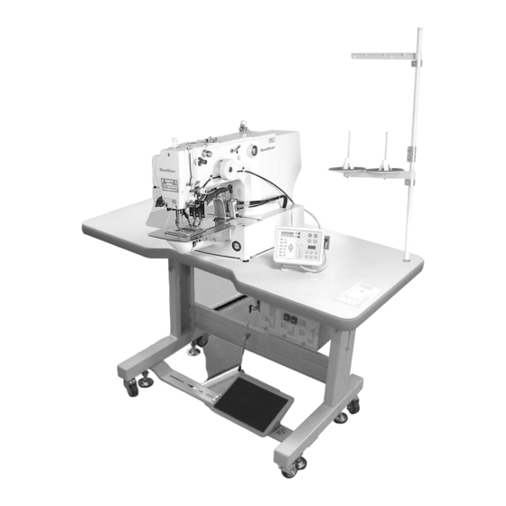
MACHINE STRUCTURE 1) Names of Each Part of the Machine Motor Cover Thread Stand Emergency Stop Switch Safety Plate Ass y Operation Box Power Switch Pedal Switch... -
Page 11: Machine Installation
MACHINE INSTALLATION 1) Machine Installation Conditions A. Do not use the machine where the voltage is over regular voltage 10% to prevent accidents B. For safe operation of the machine, use the machine under the following conditions. Surrounding Temperatuer During Operation : 5 ~40 (41 F~104 F) Surrounding Temperature During Maintenance : -10 ~60 (14 F~140 F) C. - Page 12 C. Add the hinge metal and hinge rubber to the bed. Then insert the fixing bolt into the hinge metal hole of Bolt point and fix the table as shown in the picture. Hinge Rubber Hinge [ Fig. 3 ] D.
- Page 13 F. After the cable connections beween the machine and the control box is finished, fix the cable wiring under the table as shown in the picture. (Adjust the length of the wire considering the situation of standing the machine.) Table [ Fig.
-
Page 14: The Assembly Of Peripheral Parts
4) The Assembly of Peripheral Parts A. Attach the motor cover on the back side of the machine Fixing Screw (4 positions) by using the 4 joint screws. Motor Cover [ Fig. 7 ] B. Attach the safety plate to the left side of machine by using fixing bolt. -
Page 15: Installation Method Of Air Pressure Specifications
5) Installation Method of Air Pressure Specifications A. Assembly method of filter regulator attach to right side of the table leg by using a bolt as shown in the figure. [ Fig. 10 ] B. Assembly method of solenoid valve Fix it tightly at the proper location of the table bottom by using the fixing screw. - Page 16 C. How to connect the pneumatic hoses of monolithic feed frame machine (for SPS/D-B1254 A-20 / B1263 A-20 machine) 1. Connect filter regulator and solenoid valve by using the hose 2. Insert the hoses labelled S3F and S4F to the A and B part as shown in figure. (Confirm the noses are inserted filly.) 3.
- Page 17 D. How to connect the pneumatic hoses of the separately driven feed frame machine (for SPS/D-B1254 A-22 / B1263 A-22 machine) Air Hose Hose Nipple Cap Net 1. Connect filter regulator and solenoid valve by using the hose 2. Assemble the hose with the label of S3L, S4L, S3R, S4R to the attaching part of solenoid as shown in the figure 3.
-
Page 18: Preparations Before Operating The Machine
PREPARATIONS BEFORE OPERATING THE MACHINE 1) How to Supply Oil A. Check the amount of oil left in the oil tank which is installed on the arm and supply oil stufficiently. [ Fig. 15 ] B. Check the remained amount of oil from the right window(Oil gauge window) of oil tank installed on the bed as seen in the figure, then supply oil enough through the lubrication hole on the bed cover. -
Page 19: How To Install The Needle Bar
D. Open the hook cover and supply oil till the shuttle race ring is surrounded by oil. Put the hook cover back on after finishing. Shuttle Race Ring Hook Cover [ Fig. 18 ] E. Supply sillicon oil into the sillicon oil tank which is installed on the right side of the arm. -
Page 20: How To Thread The Upper Thread
3) How to Thread the Upper Thread After placing the thread take-up lever on the top position, hang the upper thread as shown in the Figure. Concerning the thread guide of the needle bar, hang thread to use for heavy weight material as shown in Fig. hang thread to use for general and thin knit material as shown in Fig. -
Page 21: How To Adjust The Tension Of The Upper Thread And The Lower Thread
6) How to Adjust the Tension of the Upper Thread and the Lower Thread A. Adjusting the tension of the upper Thread When the tension adjusting nuts , of thread tension adjusting unit and sub-tension adjusting unit , are turned clockwise the upper thread is tightened. -
Page 22: Type)
8) How to Operate a Pedal ( A-20 Type) A. After providing with the pedal switch of 2 pressing plates, install it a proper position to work conveniently. B. When you are pressing the right pedal the feed plate is lowering down, and when you press it again, the feed plate starts rising. -
Page 23: Compressed Air Input And Air Pressure Adjusting Method
11) Compressed Air Input Air Pressure Adjusting Method A. Please connect quick joint socket that pressed air was connected to the quick joint plug attached to the table. B. Open the finger valve and input the pressed air. Reference If you close the finger valve after you use it, automatically dischange the remained air and the remained pressure is indicated as 0 MPa (0 kgf/cm ) [ Fig. -
Page 24: How To Repair The Machine
HOW TO REPAIR THE MACHINE 1) Adjusting the Height of the Needle Bar When the needle bar os at its lowest position, unfasten the DP 5 needle bar holder screw . Adjust the desired height by making the specified upper carving line fit in with the needle bar bushing. -
Page 25: Adjusting The Lower Shaft Gear And The Rocking Shaft Gear
3) Adjusting the Lower Shaft Gear and the Rocking Shaft Gear A. Unfasten screws B. While having the upper shaft turning, move the rocking shaft gear in the direction of the arrow to the position where it will move easily without load. C. -
Page 26: Adjusting The Height Of The Feed Plate
5) Adjusting the Height of the Feed Plate. Unfasten the cylinder knuckle joint nut attached on the left and right cylinders on the feed bracket . And when you raise the cylinder knuckle to direction A by rotating the cylinder shaft , the height(T) of the feed plate is set up highly, and when you lower the cylinder knuckle... - Page 27 B. Height Adjustment of Presser Bar Adjust the presser bar that end of presser bar should come out about 17mm from presser bar handle and Presser check if the needle passes through center of presser bar.If checking ends, fasten joint screw Presser Bar Holder Presser Foot...
-
Page 28: Adjusting The Parts For Thread Release
D. Adjustment of Presser Foot Stoke(Adjustment of Presser Foot UP/DOWN Motion) After unfastening stud screw of presser foot adjusting arm, placing it to A direction, presser foot stroke increases. Placing to direction B, stroke decreases. (It is set to 4mm at the moment of factory shipping). [ Fig. - Page 29 C. How to adjust the opering capacity of the thread guide disk Unfasten the thread release adjusting plate screw. Open the thread guide disk by operating the trimming devices. Adjust the opening capacity to 0.6 0.8mm for normal material and 0.8 1mm for heavy material. To increase the opening capacity, widen the angle between the thread release plate and narrow the angle to reduce the opening capacity.
-
Page 30: Adjusting The Wiper Parts
9) Adjusting the Wiper Parts A. Unfasten the crank fixing screw when a needle is stopped upward. B. Adjust the wiper crank for wiper and needle to be apart from about 40mm C. Fasten the wiper crank fixing screw D. Unfasten the wiper fixing screw and adjust it for wiper tail and needle tip to be apart from about 1mm, then fasten the wiper fixing screw 40mm... -
Page 31: Adjusting The Parts For Trimming
10) Adjusting the Parts for Trimming A. Setting the position of the trimming Cam Set the upper shaft collar and the trimming cam 1.7mm apart from each other and place the trimming cam where the trimming cam carving line accords with the upper shaft carving point. Then, tighten screw 1.7mm Carving Line Carving Point... - Page 32 C. Setting the trimming shaft in place Thread Thread Timmer Shaft Unfasten the trimming drive link screw and the Trimmer Cam trimming shaft collar screw. Make the trimming shaft tip accord with part of the arm. Tighten the screws. Screw Thread Trimming Collar for Thread Driving Link...
-
Page 33: Adjusting The Devices For Mainthread Adjustment
F. Adjusting the Moving Mes and the Fixed Mes When the meedle bar stops at the upper position, use the trimming lever adjustment screw to adjust space A between the thread separation point of the moving mes and the throat plate hole as indicated in the table. Use the fixed mes screw to adjust space B between the fixed plate and the throat plate cover as indicated in the table. -
Page 34: Adjusting The Hand Pulley Device
B. After adjusting to correct the distance from the presser Thread Winder Upper Shaft foot drive cam to the thread winder drive wheel to be Drive Wheel 1mm, fasten the joint screw. Upper Shaft front Boothing [ Fig. 57 ] 13) Adjusting the Hand Pulley Device Upper Shaft A. -
Page 35: Setting Up The X-Y Origin
15) Setting Up the X-Y Origin A. How to set up X-axis origin Separate a bed cover (left). Move the center of work clamp foot to be placed on the center of X-axis. As seen in the figure, unfasten the bolts of X-sensor plate and let the end of X-sensor plate locate on the center of sensor, then fasten the bolts with screw-driver. -
Page 36: Cause Of Breakdown And Troubleshooting
CAUSE OF BREAKDOWN AND TROUBLESHOOTING 1) Machine Part Condition of Cause of Breakdown Troubleshooting Breakdown Adjust the belt tension or exchange it. Loosing of belt tension and damage on belt. Check the fuse shortage of main shaft drive motor in Fuse shortage for main power or circuit Error on operation a controller box or exchange it... -
Page 37: Pattern List
PATTERN LIST Range of Sewing Range of Sewing Range of Sewing Stitch Stitch Stitch Pattern Pattern Pattern Model Model Model Number Number Number X (mm) Y (mm) X (mm) Y (mm) X (mm) Y (mm) - Page 38 Range of Sewing Range of Sewing Stitch Stitch Application Application Pattern Pattern Number Number X (mm) Y (mm) X (mm) Y (mm) Straight Line Heavy General Semi Materials Circle Vertical Pattern Stitch Number For Thin Range of X (mm) Materials Sewing Y (mm) Linear Vertical...
-
Page 39: Drawing Of Table
DRAWING OF TABLE... -
Page 40: Gauge List
GAUGE LIST SPS/D-B1254 / B1263 Name MA(Medium) HA(Heavy) Large Hook Option(MA) Large Hook Option(HA) Thread Take Up 08S001P-306H Lever Ass y Link Cam 02-102A-120H Needle Bar 04S001S-306H Thread Guide of Needle Bar 04S008S-306G 04S007S-306H 04S008S-306G 04S007S-306H Needle 5 #16 17 #19 5 #16 17 #19 07-022A-120M... - Page 41 Feed Plate List Standard Type SPS/D-B12 HA-20, MA-20 SPS/D-B12 HA-22, MA-22 Upper Feed Plate Depth of knurling : 0.7 Depth of knurling : 0.7 B1254 22-008A-1254 B1254 22-010A-1254, 22-011A-1254 B1263 22-008A-1263 B1263 22-009A-1263, 22-010A-1263 Lower Feed Plate Knurling depth B1254 22-034A-1254 B1263 22-032A-1263...
- Page 42 Special Option type for Label Attaching HA-22, MA-22 Label option for Separately Driven Feed Frame Upper Feed Plate Depth of knurling : 0.7 Label Size Sewing Area Order Made Parts Lower Feed Plate with knurling Order Made Parts...
-
Page 43: Pneumatic Diagram
PNEUMATIC DIAGRAM 1) Drawing of the Pneumatic Hose of SPS/D-B1254 A-20, SPS/D-B1263 A-20 Machine (for Monolithic Feed Frame) Presser Foot Cylinder(Right) Presser Foot Cylinder(Left) S34F P EB AIR IN... -
Page 44: Drawing Of The Pneumatic Hose Of Sps/D-B1254 A-22, Sps/D-B1263 A-22 Machine (For Separately Driven Feed Frame)
2) Drawing of the Pneumatic Hose of SPS/D-B1254 A-22, SPS/D-B1263 A-22 Machine (for Separately Driven Feed Frame) Presser Foot Cylinder(Right) Presser Foot Cylinder(Left) S34F S34F P EB P EB AIR IN...
Need help?
Do you have a question about the SPS/ D-B1254 Series and is the answer not in the manual?
Questions and answers