Table of Contents
Advertisement
Advertisement
Table of Contents

Related Manuals for Siemens 7MC3040-...


Summary of Contents for Siemens 7MC3040-...
- Page 1 Digital Pyrometer Radiation PA 1x, 2x, 3x 7MC3040-... 04/2017 Operating Manual...
- Page 3 Digital Radiation Pyrometer PA Ident.-Nr.: 105 3232 PA1_x_2x_3x_si_en.doc Stand: 24.04.2017 830 hm / 810 het...
- Page 4 Please note: Unless otherwise stated in this instruction manual, the instruments described herein are subject to change without prior notice, particularly modifications for the sake of technological advancement. Siemens AG Digital Factory Customer Services DF&PD DF CS SD OP ITM...
-
Page 5: Table Of Contents
Operating manual PA Contents Product Numbers ARDOCELL PA ..........1 Miscellaneous ................5 Informationen about this manual ............5 Explanation of symbols ............... 5 Liability and Warranty ................. 5 Copyright .................... 6 Safety ..................6 Intended use ..................6 User’s responsibility ................7 Safety requirements ................ - Page 6 Operating manual PA User-defined calibration / scaling of the current output..47 13.1 Calibration/scaling via CellaView ............48 13.2 Calibration/scaling via terminal connection ........48 Shielding and Grounding ............50 14.1 Potential equalisation ............... 50 Connectivity Examples ............52 15.1 Connection to VK 02/A Cable ............
- Page 7 Operating manual PA 31.6 Cable VK 02/A .................. 93 31.7 Cable VK 02/F .................. 94 Mounting combinations ............95 32.1 Mounting combination PA 20-007 ............. 95 32.2 Mounting combination PA 20-010 ............. 96 Glossary ..................97 Shipping, Packaging and Disposal ......... 98 34.1 Inspecting your shipment ..............
- Page 8 Operating manual PA...
-
Page 9: Product Numbers Ardocell Pa
Operating manual PA Product Numbers ARDOCELL PA Pyrometer Temperarute range Product number ARDOCELL PA 10 AF1 MR: 0-1000 °C, D=50:1 (Standard lens) 7MC3040-1AB10 ARDOCELL PA 10 AF1/L MR: 0-1000 °C, D=50:1 (Standard lens) 7MC3040-2AB10 ARDOCELL PA 10 AF1/C MR: 0-1000 °C, D=50:1 (Standard lens) 7MC3040-3AB10 ARDOCELL PA 10 AF 2 MR: 0-1000 °C, D=48:1 (Close-up lens) - Page 10 Operating manual PA Pyrometer Temperarute range Product number ARDOCELL PA 20 AF 4/C MR: 250-2000 °C, D=40:1 (Wide-angle lens) 7MC 3040-3AE20 ARDOCELL PA 20 AF 5 MR: 350-2500 °C, D=175:1 (Standard lens) 7MC 3040-1AF20 ARDOCELL PA 20 AF 5/L MR: 350-2500 °C, D=175:1 (Standard lens) 7MC 3040-2AF20 ARDOCELL PA 20 AF 5/C MR: 350-2500 °C, D=175:1 (Standard lens)
- Page 11 Operating manual PA Pyrometer Temperarute range Product number ARDOCELL PA 29 AF 4 MR: 250-2000 °C, D=55:1 (Wide-angle lens) 7MC 3040-1AE29 ARDOCELL PA 29 AF 4/L MR: 250-2000 °C, D=55:1 (Wide-angle lens) 7MC 3040-2AE29 ARDOCELL PA 29 AF 4/C MR: 250-2000 °C, D=55:1 (Wide-angle lens) 7MC 3040-3AE29 ARDOCELL PA 29 AF 10 MR: 150-800 °C, D=48:1 (F50 lens)
- Page 12 Operating manual PA Pyrometer Temperarute range Product number ARDOCELL PA 30 AF 5/L MR: 500-2500 °C, D=430:1 (Telephoto lens) 7MC 3040-2AF30 ARDOCELL PA 30 AF 5/C MR: 500-2500 °C, D=430:1 (Telephoto lens) 7MC 3040-3AF30 ARDOCELL PA 35 AF 1 MR: 600-3000 °C, D=210:1 (Standard lens) 7MC 3040-1AB35 ARDOCELL PA 35 AF 1/L MR: 600-3000 °C, D=210:1 (Standard lens)
-
Page 13: Miscellaneous
Operating manual PA Miscellaneous Informationen about this manual The Operating Manual shall enable the user to properly install the pyrometer and those accessories which are necessary. Before starting installation, be sure to read and understand this entire manual, in particular the chapter on safety! The instructions contained in this manual, especially those concerning safety, as well as site-specific regulations governing UV radiation must be complied with at all times! Explanation of symbols... -
Page 14: Copyright
Operating manual PA Copyright This Operating Manual should be treated as confidential. It is solely in- tended for use by persons involved with the instrument. This manual may not be made available to a third party without prior Manufacturer’s con- sent. -
Page 15: 3.2 User's Responsibility
Operating manual PA 3.2 User’s responsibility The pyrometer may only be used when it is in perfect working condition. Safety requirements The instrument works with an operating voltage of 24 VDC. The voltage re- quired for operation must be supplied by a separate power supply. This power supply unit must conform to directive DIN IEC 61010. - Page 16 Operating manual PA 4.82 µm. thus measuring the temperature from the near surface area of the glass. Changes in thickness, different types of glass, or varying mois- ture contents in the atmosphere do not affect the measurement reading owing to the wavelength used The ARDOCELL PA 28 and PA 29 were designed with a special band- stop filter and sensor which ignore interfering IR radiation from sources such as daylight or laser beams.
-
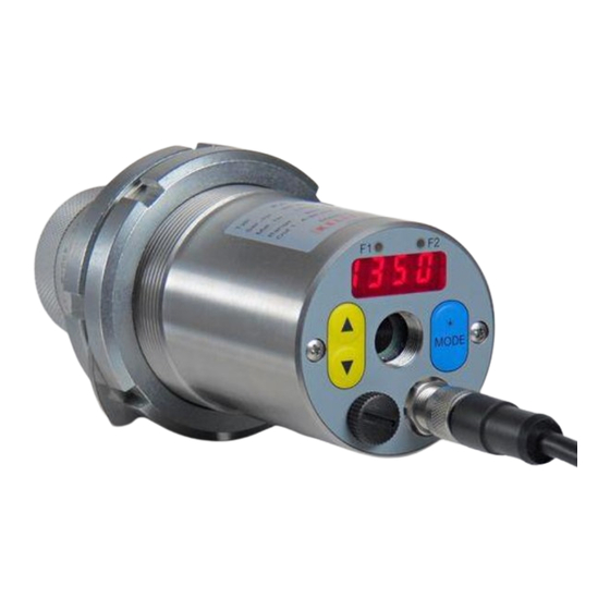
Page 17: Operating Controls And Display
Operating manual PA When ambient temperatures are higher than the admissible working temperature, the output current is > 20.5 mA. PA also features an analogue voltage input which can be used as an al- ternative to current output 2. The emissivity factor or a correction for re- flected ambient temperature can be controlled using this voltage input. -
Page 18: Quick Reference Guide
Operating manual PA 5 Quick Reference Guide PA Connector Pin Assignment Shielding 1 = white + 24 V DC 2 = brown Digital in- / output 1 3 = green Analogue output 2 4 = yellow Analogue output 1 5 = grey Serial interface RS485 (A) (Tx-/D-) 6 = pink Serial interface RS485 (B) (Tx+/D+) -
Page 19: 5.2 Current Outputs 0/4 - 20Ma
Operating manual PA A self-test is performed when the instrument is switched on. The display will briefly indicate the software version and after that the emissivity set- ting. When the self-test is completed the pyrometer is ready for operation and the display will show the current temperature reading. ... -
Page 20: Switching Output
Operating manual PA When only one current output is required, Output 1 should be selected (Pin 4) Switching output All pyrometers of the PA Series feature two switching outputs which can be configured as digital outputs or digital inputs. The open collector out- puts allow for a voltage of +24 V DC. -
Page 21: Pyrometer Alignment To Target
Operating manual PA The pyrometer’s optical path must remain unobstructed. Any interference or obstacle may lead to measurement errors. Pyrometer Alignment to Target For accurate temperature measurement, it is essential that the py- rometer is correctly aimed and focused at the target object. Make sure that the optical path is not obscured because this would most likely impair accuracy. -
Page 22: Safety Instructions And Precautions
Operating manual PA Safety instructions and precautions The user must be familiar with following safety instructions. Laser Radiation Hazard Laser radiation can be harmful to eye! PA pyrometer operates with a class 2 red light laser. Direct prolonged viewing of a laser beam can injure the retina. Therefore, the following safety precautions must be strictly observed, otherwise the laser may not be operated! ... -
Page 23: Pyrometer With Camera
Operating manual PA Fig. 6.2 Laser warning label affixed to the pyrometer Laser warning label must be visible! If the pyrometer is installed within a machine or equipment in such a way that the instrument’s warning label is visibly blocked, additional laser warning labels (not included in scope of delivery) must be affixed to the equipment or accessory in immediate vicinity to the laser beam emission path opening. -
Page 24: Setting Emissivity
Operating manual PA Press the MODE button while in normal operating mode to switch to "configuration layer" mode. Use ▲▼ to select the configuration layer for the parameter you wish to set. Press MODE to confirm. Press ▲▼ to select the particular pa- rameter. -
Page 25: Output Current Range
Operating manual PA A pyrometer measures temperature by detecting the radiant energy emit- ted from an object’s surface in the form of electromagnetic waves. The temperature reading not only depends on the intensity of the object’s thermal radiation (how hot the object is), but also on the material’s par- ticular surface characteristics and thus its specific ability to emit thermal energy. -
Page 26: Simulated Current Signal For Functional Testing
Operating manual PA Simulated current signal for functional testing After initial installation, you should perform a function test to verify that temperature data is correctly transmitted to the controller. To do so, use the push-buttons on the pyrometer rear panel to simulate a temperature reading, which is applied as an output current signal scaled to the se- lected current range. - Page 27 Operating manual PA Ambient Temperature Compensation Under normal conditions, PA pyrometer should produce highly accurate temperature readings once you have set the emissivity and transmit- tance factors. Certain conditions, however, will require that you make an additional correction. Object surfaces which have very low emissivity will reflect thermal radiation from their surroundings.
- Page 28 Operating manual PA Temperature offset using linear interpolation When necessary, PA pyrometer allows you to program an offset for the temperature reading reported. The offset correction can be configured individually with a minimum of 2 and a maximum of 10 interpolating points (X/Y nodes).
- Page 29 Operating manual PA analogue output signal output signal without smoothing output signal with smoothing time Min/Max Data PA pyrometer features data memory to store minimum and maximum (peak) temperature readings. This feature can be configured in one of the following modes: ...
- Page 30 Operating manual PA not drop between targeted objects. The peak temperature reading will be held for a preset time period. Configure a hold time between 0.01 to 999 sec. either from your PC ter- minal or using the pyrometer’s rear panel buttons. The maximum tem- perature sampled during the defined hold time will be saved.
- Page 31 Operating manual PA Limit 1 (LI. 1) Before beginning the measurement, the temperature reading must have been lower than Limit 1 at least once. A.RST= If Autoreset ( ) the limit 1 will be ignored Limit 2 (LI. 2) Limit 2 must be exceeded at least for the T.DEL duration of the time delay ( T.DEL...
- Page 32 Operating manual PA ference is higher than the plausibility threshold , the transmitted da- ta will be „0“ and the average value will remain unchanged. TSP_ Plausibility ( Threshold for plausiblity check: lower limit which is acceptable for a valid measure- ment.
-
Page 33: I/O Configuration
Operating manual PA I/O Configuration Selectable current output range You will need to define the current loop scale and define a source for an analogue output signal. For a spectral pyrometer the sources for ana- logue output Ao1 is Spectral channel 1 In the normal operating mode, Spectral channel 1 will be shown on the display. - Page 34 Operating manual PA C010 Make these settings in configuration layer with parameters AO1.S, AO1._, AO1.~ AO1.4 for analogue output 1, and in the same manner for analogue output 2. Configuration example PA 10: Ao1: temperature reading of spectral channel 1 0 - 1000 °C ≡...
- Page 35 Operating manual PA When the digital output is to be used as a limit switch, you can configure the following parameters: Signal source Signal function and direction Limit and hysteresis at function „level“ Lower / upper limit at function = “Range” ...
- Page 36 Operating manual PA Function „Level“ Temperature [°] Switching thresh- old (level) Hysteresis Digital output [V] 24 V Switch signal with hold time = 0 and delay time = 0 s Delay time Delay time Digital output [V] Hold time Hold time 24 V Switch signal with hold time and...
- Page 37 Operating manual PA Function “Range” Temp. [°C] Switching threshold = „Range“ Digital output [V] 24 V Switch signal with hold time = 0 and delay time = 0 s Delay time Delay time Digital output [V] Hold time Hold time 24 V Switch signal with hold time and delay...
- Page 38 Operating manual PA Digital inputs If you want to use the digital output as an input, you must first manually deactivate the digital output and configure the following parameters: Select a current output range (either 0 – 20 mA or 4 – 20 mA) for Ao1/Ao2 ...
-
Page 39: General Functions (Configuration Layer C011)
Operating manual PA AI.V2 = 1200 (temperature 1200 °C) C011 General functions (configuration layer Green Status LED You can assign specific functions to the LED: LED is continuously lit to indicate 24 V operating voltage LED indicates status of switching output 1 ... -
Page 40: Simulate Current Signals For Analogue Output Ao1 And Ao2
Operating manual PA Exposure control only applies to the measurement area. ( C.TBC Exposure control applies to the entire field of view. ( C.TBC = off) As a standard, the target brightness control feature works in the target area to show bright objects against a dark background or dark objects against a bright background with an ideal brightness. -
Page 41: Setting Parameters At The Device
Operating manual PA nection. When you have completed the function test, exit by pressing " " and return to normal operating mode. Setting Parameters at the device In addition to the configuration possibilities described in Chapter 7, many parameters can be adjusted at the rear panel using push buttons. These settings can be accessed via configuration layers. - Page 42 Operating manual PA simple smoothing AUTO subsequent smoothing (only model PA1x) FIL.T Smoothing time time t98 in sec.for simple smoothing lowest (min.)temperature, single MEM.1 Min/Max memory highest (max.) temperature, single double maximum DBL.M ATD function in process DIS.M Hold time for MEM.T Hold time in sec.
- Page 43 Operating manual PA C010 Configuration I/O (configuration layer: Parame- Function Explanation AO1.S Ao1 select source Spectral channel 1 Ao1 define lower lim- AO1._ it of temp. span Ao1 define upper AO1.~ limit of temp. span 0-20 0-20mA 4-20 4-20mA AO1.4 Ao1 0/4 - 20mA EXT.1 digital input 1: 0V=0-20mA 24V=4-20mA...
- Page 44 Operating manual PA Lambda 1 L1.PR Lambda 1 without peak picker Device inner temperature M.TR.1 Triggered by ATD function Lambda 1** A.AC.1 Measuring time ATD Lamda 1** Swich direction “Level” (output activ if limit LVL. excess) Switch direction “Level” / output inverted LVL.- DO2.F Do2 function...
- Page 45 Operating manual PA C011 General Functions (configuration layer: Parameter Function Explanation LED indicates 24V LED indicates digital output 1 LED.G Green status LED LED indicates digital output 2 LED indicates running measurement in TAC1 mode for ADT function keypress laser disabled PILO.
-
Page 46: Cellaview Software
The CellaView software displays, evaluates and stores the temperature readings of your pyrometer. Download the CellaView software here: http://www.industry.siemens.com/services/global/de/sirent/verkauf/Documents/software/cellaview.zip Installation of the USB driver The ARDOCELL PA pyrometer can be addressed via a special driver. On systems with Windows 7, 8 or 10 the driver installs a virtual COM in- terface which allows access to the serial port of the pyrometer. -
Page 47: How To Operate The Pyrometer With The Cellaview Software
Operating manual PA First, open the Run dialog box by using the Windows key + R key combi- nation. Then enter the command “devgmt.msc.” and click OK to open the Device Manager. Then click Ports (COM and LPT). You will see a listing of ports and should now be able to see which COM Port the PA USB connection assigned to. -
Page 48: Cellaview Via Usb Point-To-Point Connection
Operating manual PA 11.1 CellaView via USB point-to-point connection Install the USB driver Connect the pyrometer to the PC Start CellaView Select the correct COM port or use the CellaView search function. For more information on how to work with CellaView read the separate CellaView manual. -
Page 49: Cellaview Via Rs485 Bus Connection
Operating manual PA Caution ! If the supply voltage or current output are conducted via this ca- ble, then make sure to consider the voltage drop if the cable length is greater than 100 m. Disconnect the pyrometer from any voltage source ... - Page 50 Operating manual PA Caution ! All pyrometers must be connected to the same voltage supply. The maximum length of the branch lines to the pyrometer is 5 m.
-
Page 51: Termination Of Rs485 Bus
Operating manual PA Disconnect the pyrometer from any voltage source Activate or deactivate the termination of the respective partici- pant (see termination of RS485 bus) Install all required electric connections Connect the converter with the PC ... -
Page 52: Serial Data Transmission Of Temperature Data
Operating manual PA Enter press Execute the [RETURN] Main Menu or [ESC] command Select [KEY] Backspace Enter press Execute the [RETURN] Submenu 1 command or [ESC] [ESC] Select [KEY] Backspace Press [] Enter press Execute the [RETURN] Submenu 2 command or [ESC] [ESC] To set the pyrometer to the terminal mode, simultaneously hold down the... -
Page 53: Terminal Connection Via Usb
Operating manual PA The cycle time in which the temperature reading is transmitted can be set at the PC terminal (minimum cycle duration is 0.1 second). 12.2 Terminal connection via USB For communication through a terminal connection via USB set the pa- TERM rameter on the pyrometer to USB (default setting). - Page 54 Operating manual PA Moreover, use a converter with galvanic isolation (e.g. W&T 38211) to avoid problems with ground loops. Caution ! If the supply voltage or current output are conducted via this ca- ble, then make sure to consider the voltage drop if the cable length is greater than 100 m.
-
Page 55: User-Defined Calibration / Scaling Of The Current Output
Operating manual PA User-defined calibration / scaling of the current out- If necessary, the pyrometer can be adjusted with a user-defined calibra- tion function. The following drawing explains the effects for offset and factor. shall Current state Influence - factor Influence - offset Pyrometer Caution:... -
Page 56: Calibration/Scaling Via Cellaview
Operating manual PA 13.1 Calibration/scaling via CellaView To use the user-defined calibration function, activate it first in expert mode. Start CellaView Open the menu Settings Extras -> Settings Select expert mode and activate editable calibration Close the menu ... - Page 57 Operating manual PA applies to data acquisition parameters and input/output settings. Use keys "B", "C" and "D" for direct access to enable the adjustments. If you make a mistake while making the adjustments, simply enter off- set=0.0 und factor=1.0, or set User Cal. to „off“. Command "A"...
-
Page 58: Shielding And Grounding
Operating manual PA Shielding and Grounding 14.1 Potential equalisation Caution: All applicable laws and codes must be complied with at all times. The pyrometer housing is connected to the shielding via the cable connector! Differences in ground potentials might cause an equalis- ing current to flow between devices through a cable shielded at both ends. - Page 59 Operating manual PA Pyrometer PA Shielded cable Shield clamp Interference voltage To avoid an equalising current, the pyrometer can be mounted elec- trically insulated. The shielding must be connected to the plant’s earthing system. Caution: If the pyrometer is installed without an insulator and without potential equalisation, the interference voltage may not ex- ceed 48V.
-
Page 60: Connectivity Examples
Operating manual PA Connectivity Examples 15.1 Connection to VK 02/A Cable Voltage supply 24 V white yellow Load 0 ... 500 Ω Current output 1 0/4 - 20 mA Flange plug (View pin side 15.2 Connection to DA 230 digital display unit white +24 V yellow... -
Page 61: Theory Of Non-Contact Temperature Measurements
Operating manual PA Theory of Non-Contact Temperature Measurements All materials radiate thermal energy in all states of aggregation above absolute zero. This radiation is mainly caused by atomic or molecular oscillations. This temperature radiation is only a limited sector within the total electromagnetic radiation spectrum. -
Page 62: Measurements Of Real Radiators
Operating manual PA Most burning, annealing and hardening furnaces emit a radiation of near- ly '1' which corresponds to the conditions of a black body if the aperture through which the measurement is made is relatively small. 16.3 Measurements of Real Radiators Real radiation sources are characterized by the relation of the emitted radiation to the radiation of a black body with the same temperature. -
Page 63: Emissivity Coefficient Table Pa 10
Operating manual PA 16.4 Emissivity Coefficient Table PA 10 List of emissivity coefficients of different materials in % Pyrometer PA 10 Wavelength 8 - 14 µm "Black body" Aluminium oxide Asphalt 90 - 98 Baking oven, dark colour Concrete 55 - 65 Bitumem (roofing paper) Bread in baking oven... -
Page 64: Emissivity Coefficient Table Pa 20 - Pa 30
Operating manual PA Emissivity Coefficient Table PA 20 – PA 30 16.5 List of emissivity coefficients of different materials in % Pyromter PA 20 PA 30 Wavelength 1.1 – 1.7 m 0.8 – 1.1 m "Black Body" Aluminium, polished Aluminium, blackened Asbestos cement Bronce, polished... -
Page 65: Maintenance
Operating manual PA Maintenance 17.1 Cleaning the pyrometer lens A false temperature reading will be given when the lens is dirty. There- fore check the lens periodically and clean it, if necessary. Dust can be removed by simply blowing it away or by using a soft brush. A special lens cleaning cloth is ideal, but any soft, clean, lint-free cloth will be suitable. -
Page 66: Technical Data Pa 10
Operating manual PA Technical Data PA 10 Measuring ranges : Repeatability: Housing material: (adjustable in partial Stainless steel ranges): Sighting device: Mounting: 0 ... 1000 °C through-the-lens sighting with External thread M 65 x 2 Sensor: target marking, laser spot light length 40 mm thin-film thermopile or integrated camera... -
Page 67: Field Of View Diagrams For Pa 10
Operating manual PA 18.1 Field of View Diagrams for PA 10 ∞) Target diameter [mm] PZ 10.01 (0.3 m - D = 50 :1 Target Distance [m] PZ 10.05 (0.15 – 0.3 m Target diameter [mm] D = 48 :1 Target distance [m]... -
Page 68: Technical Data Pa 13
Operating manual PA Technical Data PA 13 Measuring ranges : Sighting device: Mounting: (adjustable in partial through-the-lens sighting with External thread M 65 x 2 ranges): target marking, laser spot light length 40 mm 500 ... 1600 °C or integrated camera Weight: Sensor: Ambient operating... -
Page 69: Field Of View Diagrams For Pa 13
Operating manual PA 19.1 Field of View Diagrams for PA 13 ∞) Target diameter [mm] PZ 15.03 (0.6 m - D = 45 :1 Target distance [m]... -
Page 70: Technical Data Pa 15
Operating manual PA Technical Data PA 15 Measuring ranges : Repeatability: Mounting: (adjustable in partial External thread M 65 x 2 ranges): length 40 mm Sighting device: MR I: 500 ... 2500 °C MR II: 300 ... 1300 °C through-the-lens sighting with Weight: target marking, laser spot light Approx. -
Page 71: Field Of View Diagrams For Pa 15
Operating manual PA 20.1 Field of View Diagrams for PA 15 ∞) Target diameter [mm] PZ 15.03 (0.8 m - D = 70 :1 Target distance [m] ∞) Target diameter [mm] PZ 15.03 (0.8 m - D = 45 :1 Target distance [m]... -
Page 72: Technical Data Pa 17
Operating manual PA 21 Technical Data PA 17 Measuring ranges : Sighting device: Mounting: (adjustable in partial through-the-lens sighting with ranges): target marking, laser spot light External thread M 65 x 2 400 ... 2000 °C or integrated camera length 40 mm Ambient operating Sensor: temperature:... -
Page 73: Field Of View Diagram For Pa 17
Operating manual PA 21.1 Field of View Diagram for PA 17 PZ 15.03 (0.8 m - ∞) Target diameter [mm] D = 75 :1 Target distance [m]... -
Page 74: Technical Data Pa 20
Operating manual PA Technical Data PA 20 Measuring ranges: Linearisation: Housing material: (adjustable in partial digital via microcontroller Stainless steel ranges) Repeatability: 250 ... 2000 °C Mounting: External thread M 65 x 2 Sensors: length 40 mm photo diode Sighting device: through-the-lens sighting with Weight: Spectral sensitivity:... -
Page 75: Field Of View Diagrams For Pa 20
Operating manual PA 22.1 Field of View Diagrams for PA 20 Target diameter [mm] ∞) PZ 20.01 (0,4 m - D = 175 :1 Target distance PZ 20.03 (0.2 – 0.4 Target diameter [mm] D = 150 :1 Target distance [m]... - Page 76 Operating manual PA Target diameter [mm] ∞) PZ 20.05 (0.2 m - D = 40 :1 Target distance [m] Target diameter [mm] ∞) PZ 20.06 (1.2 m - D = 275 :1 Target distance [m] PA 20.06 (0.6 m - ∞) Target diameter [mm] 10.5...
-
Page 77: Technical Data Pa 28
Operating manual PA 23 Technical Data PA 28 Measuring ranges: Sighting device: Housing material: (adjustable in partial through-the-lens sighting with Stainless steel ranges) target marking, laser spot light 75 ... 650 °C or integrated camera Mounting: External thread M 65 x 2 Sensors: Ambient operating length 40 mm... -
Page 78: Minimum Measured Temperature In Relation To The Ambient Temperature And The Emissivity
Operating manual PA 23.1 Minimum measured temperature in relation to the ambient tem- perature and the emissivity 23.2 Field of View Diagram for PA 28 ∞) Target diameter [mm] PZ 20.08 (0.3 m - D = 48 :1 Target distance [m]... -
Page 79: Technical Data Pa 29 (150
Operating manual PA Technical Data PA 29 (150 … 800 °C) Measuring ranges: Sighting device: Housing material: (adjustable in partial through-the-lens sighting with Stainless steel ranges) target marking, laser spot light 150 ... 800 °C or integrated camera Mounting: External thread M 65 x 2 Sensors: length 40 mm Ambient operating... -
Page 80: Field Of View Diagrams For Pa 29
Operating manual PA 24.1 Field of View Diagrams for PA 29 ∞) Target diameter [mm] PZ 20.08 (0.3 m - D = 48 :1 Target Distance [m]... -
Page 81: Technical Data Pa 29 (180
Operating manual PA Technical Data PA 29 (180 … 1200 °C) Measuring ranges: Repeatability: Housing material: (adjustable in partial Stainless steel ranges) Sighting device: 180 ... 1200 °C Mounting: through-the-lens sighting with External thread M 65 x 2 Sensors: target marking,laser spot light or length 40 mm photo diode integrated camera... -
Page 82: Field Of View Diagrams For Pa 29
Operating manual PA 25.1 Field of View Diagrams for PA 29 PZ 20.03 (0.2 – 0.4 m) Target diameter [mm] D = 56 :1 Target Distance [m] ∞) Target diameter [mm] PZ 20.01 (0,4 m - D = 60 :1 Target Distance [m]... - Page 83 Operating manual PA ∞) Target diameter [mm] PZ 20.06 (1.2 m - D = 96 :1 Target Distance [m]...
-
Page 84: Technical Data Pa 29 (250
Operating manual PA Technical Data PA 29 (250 … 2000 °C) Measuring ranges: Linearisation: Housing material: digital via microcontroller (adjustable in partial Stainless steel ranges) 250 ... 2000 °C Mounting: Repeatability: External thread M 65 x 2 Sensors: length 40 mm photo diode Sighting device: Weight:... -
Page 85: Field Of View Diagrams For Pa 29
Operating manual PA 26.1 Field of View Diagrams for PA 29 Target diameter [mm] ∞) PZ 20.01 (0,4 m - D = 210 :1 Target distance [m] PZ 20.03 (0.2 – 0.4 m) Target diameter [mm] D = 200 :1 Target distance [m]... - Page 86 Operating manual PA ∞) Target diameter [mm] PZ 20.05 (0.2 m - D = 55 :1 Target distance [m] ∞) Target diameter [mm] PZ 20.06 (1.2 m - D = 310 :1 Target distance [m]...
-
Page 87: Technical Data Pa 30
Operating manual PA Technical Data PA 30 Measuring ranges: Linearisation: Dimensions: (adjustable in partial digital via microcontroller Ø 65 x 220 mm ranges) (when connector is attached) Repeatability: 500 ... 2500 °C Housing material: Sensors: Stainless steel photo diode Sighting device: through-the-lens sighting with Mounting: Spectral sensitivity:... -
Page 88: Field Of View Diagrams For Pa 30
Operating manual PA 27.1 Field of View Diagrams for PA 30 Target diameter [mm] ∞) PZ 20.01 (0,4 m - D = 210 :1 Target distance [m] PZ 20.03 (0.2 – 0.4 m) Target diameter [mm] D = 200 :1 Target distance [m]... - Page 89 Operating manual PA ∞) Target diameter [mm] PZ 20.05 (0.2 m - D = 55 :1 Target distance [m] ∞) Target diameter [mm] PZ 20.06 (1.2 m - D = 310 :1 Target distance [m] PA 20.06 (0.6 m - ∞) Target diameter [mm] D = 430 :1...
-
Page 90: Technical Data Pa 35
Operating manual PA Technical Data PA 35 Measuring ranges: Linearisation: Housing material: (adjustable in partial digital via microcontroller Stainless steel ranges) Repeatability: 600 ... 3000 °C Mounting: External thread M 65 x 2 Sensors: length 40 mm photo diode Sighting device: through-the-lens sighting with Weight: Spectral sensitivity:... -
Page 91: Field Of View Diagrams For Pa 35
Operating manual PA 28.1 Field of View Diagrams for PA 35 Target diameter [mm] ∞) PZ 20.01 (0,4 m - D = 210 :1 Target distance [m] PZ 20.03 (0.2 – 0.4 m) Target diameter [mm] D = 200 :1 Target distance [m]... - Page 92 Operating manual PA ∞) Target diameter [mm] PZ 20.05 (0.2 m - D = 55 :1 Target distance [m] ∞) Target diameter [mm] PZ 20.06 (1.2 m - D = 310 :1 Target distance [m] PA 20.06 (0,6 m - ∞) Target diameter [mm] D = 430 :1...
-
Page 93: Dimensions
Operating manual PA Dimensions... -
Page 94: Technical Data Camera
Operating manual PA Technical data camera Video-System: Composite Video PAL, 1 Vpp, 75 Ohm Connection: Pyrometer -> TNC plug, monitor-> chinch or BNC (video cable VK 02/F), electrically isolated from the power supply of the pyrometer Resolution: 722 x 576 pixel ... - Page 95 Operating manual PA Optic Area target size [m] HFOV 16.2 44.9 54.4 92.7 [mm] Standard 20.01 VFOV 12.1 33.7 40.8 69.5 [mm] HFOV 14.1 19.8 [mm] Close-up 20.03 VFOV 10.6 14.8 [mm] HFOV 32.5 56.4 86.3 [mm] Tele lens 20.06 VFOV 24.4 42.3...
-
Page 96: Accessories
Operating manual PA Accessories Description Product Name Article No. Cable VK 02/A 101 3909 length 5 m, 8 x 0.25 mm², shielded Video cable VK 02/F 101 1446 Polarising filter PA 20/P 100 9974 Mounting bracket PA 11/U 100 9679 Lock nut KM 13 513 854... -
Page 97: Mounting Angle Pa 11/K
Operating manual PA 31.1 Mounting angle PA 11/K Pyrometer PA Mounting angle PA 11/K... -
Page 98: Polarising Filter
Operating manual PA 31.2 Polarising filter Pyrometer PA Polarising filter PA 20/P... -
Page 99: Mounting Bracket Ps 11/U
Operating manual PA 31.3 Mounting bracket PS 11/U Pyrometer PA Mounting bracket PA 11/U PA... -
Page 100: Zns Window
Operating manual PA 31.4 ZnS Window For pyrometer PA 10 31.5 Quartz window PA 20/I and sapphire window PA 15/I Quartz window for pyrometer PA 20, PA 3x Sapphire window for pyrometer PA 13 and PA 15 CAUTION ! The replacement of the protection glass can be performed only by authorized person. -
Page 101: Cable Vk 02/A
Operating manual PA 31.6 Cable VK 02/A Ident. - Nr. 101 3909... -
Page 102: Cable Vk 02/F
Operating manual PA 31.7 Cable VK 02/F Ident. - Nr. 103 1446... -
Page 103: Mounting Combinations
Operating manual PA Mounting combinations 32.1 Mounting combination PA 20-007... -
Page 104: Mounting Combination Pa 20-010
Operating manual PA 32.2 Mounting combination PA 20-010... -
Page 105: Glossary
Operating manual PA Glossary Autoprint After connecting the power supply, the pyrometer automatically begins transmitting measurement data via the serial interface. Print cycle time The cycle time for the temperature data output via the serial interface. Distance to target size ratio Describes the ratio between the pyrometer-to-object distance and the target spot diameter. -
Page 106: Shipping, Packaging And Disposal
Should you discover a concealed loss or damage, report it to SIEMENS and to the freight carrier immediately. If the period for filing claims has expired, you will no longer be able to make any claims for compensation of damage or loss. -
Page 107: Copyright
Operating manual PA Copyright Portions of avr-libc are Copyright (c) 1999-2007 Keith Gudger, Bjoern Haase, Steinar Haugen, Peter Jansen, Reinhard Jessich, Magnus Johansson, Artur Lipowski, Marek Michalkiewicz, Colin O'Flynn, Bob Paddock, Reiner Patommel, Michael Rickman, Theodore A. Roth, Juergen Schilling, Philip Soeberg, Anatoly Sokolov, Nils Kristian Strom,... -
Page 108: Default Settings
Operating manual PA Default settings 36.1 Temperature measurement via spectral channel 1 (configura- C001 tion layer: Parameter Function Default User settings EPS.1 Emissivity factor L1 99.0%, 99.%* TAU.1 Transmission factor L1 100 % Ambient temperature BAC.1 compensation Temperature of BAC.T ambient source of radia- tion Influence of ambient IR... -
Page 109: Configuration I/O (Configuration Layer: C010)
Operating manual PA C010 36.2 Configuration I/O (configuration layer: Parameter Function Default User settings AO1.S Ao1 select source Lamda 1 Ao1 define lower limit of Measuring range AO1._ temp. span begin Ao1 define upper limit of Measuring range AO1.~ temp. span 4 –... -
Page 110: General Functions (Configuration Layer: C011)
Operating manual PA C011 36.3 General Functions (configuration layer: Parameter Function Default User settings LED.G Green status LED PILO. Activate laser* PIL.T Laser ON-time* 2 min TERM. Assign Interface Automatic temperature A.STR. data output Cycle for automatic 0.1 s A.CYC. temp. - Page 111 Operating manual PA...
- Page 116 Siemens AG Digital Factory Customer Services DF&PD DF CS SD OP ITM Telefon +49 (911) 750-9600 +49 (911) 750-9609 Email: sirent.industry@siemens.com Office/Testing Warehouse/Counter service Breslauer Str. 5 Gundelfinger Str. 20 90766 Fürth 90451 Nürnberg Germany Germany Subject to change without notice...
Need help?
Do you have a question about the 7MC3040-... and is the answer not in the manual?
Questions and answers