Siemens SITRANS F Series Operating Instructions Manual
Electromagnetic flowmeters
Hide thumbs
Also See for SITRANS F Series:
- Operating instructions manual (362 pages) ,
- Quick start manual (220 pages) ,
- Manual (188 pages)
Table of Contents
Advertisement
Quick Links
SITRANS F
Electromagnetic flowmeters
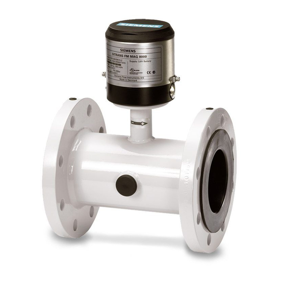
SITRANS FM MAG 8000
Operating Instructions
7ME681. MAG 8000
7ME682. MAG 8000 CT
03/2020
A5E03071515-AH
Introduction
Safety notes
Description
Installing/Mounting
Connecting
Commissioning
Operating
Service and maintenance
Diagnostics and
Troubleshooting
Technical data
Product documentation and
support
Spare parts/Accessories
Flow Tool
Qualification certificate
Unit conversion table
Parameter lists
Sizing sensor
Features
1
2
3
4
5
6
7
8
9
10
A
B
C
D
E
F
G
H
Advertisement
Table of Contents


Need help?
Do you have a question about the SITRANS F Series and is the answer not in the manual?
Questions and answers