Siemens SIWAREX WL230 Equipment Manual
Compact mounting units and guide elements sb-s sa
Hide thumbs
Also See for SIWAREX WL230:
- Operating instructions manual (48 pages) ,
- Manual (36 pages) ,
- Operating instructions manual (98 pages)
Table of Contents
Advertisement
Quick Links
SIWAREX WL230
Compact mounting units and
guide elements
SB-S SA
Equipment Manual
7MH5707-4AA01 (compact mounting unit 0.5 to 1 t)
7MH5707-4GA01 (compact mounting unit 2 t)
7MH5707-4PA01 (compact mounting unit 5 t)
7MH5707-4GE00 (guide element 0.5 to 2 t)
7MH5707-4PE00 (guide element 5 t)
12/2020
A5E02390707B-03
Introduction
Safety notes
Description
Application planning
Installation
Service and maintenance
Technical data
Dimension drawings
Ordering data
Product documentation and
support
1
2
3
4
5
6
7
8
9
A
Advertisement
Table of Contents

Related Manuals for Siemens SIWAREX WL230


Summary of Contents for Siemens SIWAREX WL230
- Page 1 Introduction Safety notes Description SIWAREX WL230 Application planning Compact mounting units and guide elements Installation SB-S SA Service and maintenance Equipment Manual Technical data Dimension drawings Ordering data Product documentation and support 7MH5707-4AA01 (compact mounting unit 0.5 to 1 t)
- Page 2 Note the following: WARNING Siemens products may only be used for the applications described in the catalog and in the relevant technical documentation. If products and components from other manufacturers are used, these must be recommended or approved by Siemens. Proper transport, storage, installation, assembly, commissioning, operation and maintenance are required to ensure that the products operate safely and without any problems.
-
Page 3: Table Of Contents
Table of contents Introduction ............................5 Purpose of this documentation .................... 5 Document history ........................ 5 Checking the consignment....................6 Scope of delivery for compact mounting unit ............... 6 Scope of delivery guide element ..................7 Security information ......................7 Notes on warranty ....................... - Page 4 Table of contents Installing the compact installation unit................27 5.2.1 General installation information..................27 5.2.2 Overview ........................... 27 5.2.3 Preparing the load cell ....................... 28 5.2.4 Preparing the compact installation unit ................28 5.2.5 Installing the load cell in the compact installation unit............28 5.2.6 Installing the compact installation unit................
-
Page 5: Introduction
See also Operating instructions SIWAREX WL200 load cells (https:// support.industry.siemens.com/cs/ww/en/view/109749190) Document history The most important changes in the documentation when compared with the respective previous edition are given in the following table. Manual edition... -
Page 6: Checking The Consignment
Introduction 1.4 Scope of delivery for compact mounting unit Checking the consignment 1. Check the packaging and the delivered items for visible damages. 2. Report any claims for damages immediately to the shipping company. 3. Retain damaged parts for clarification. 4. -
Page 7: Scope Of Delivery Guide Element
Scope of delivery guide element Security information Siemens provides products and solutions with industrial security functions that support the secure operation of plants, systems, machines, and networks. In order to protect plants, systems, machines and networks against cyber threats, it is necessary to implement –... -
Page 8: Notes On Warranty
The content reflects the technical status at the time of publishing. Siemens reserves the right to make technical changes in the course of further development. -
Page 9: Safety Notes
Safety notes Prerequisites for safe use This device left the factory in good working condition. In order to maintain this status and to ensure safe operation of the device, observe these instructions and all the specifications relevant to safety. Observe the information and symbols on the device. Do not remove any information or symbols from the device. -
Page 10: Requirements For Special Applications
Note Operation under special ambient conditions We highly recommend that you contact your Siemens representative or our application department before you operate the device under special ambient conditions as can be encountered in nuclear power plants or when the device is used for research and development purposes. -
Page 11: Description
• Parts made of stainless steel for applications in the food and pharmaceutical industries Compact mounting unit for SIWAREX WL230 SB‑S SA The self-centering compact mounting unit for SIWAREX WL230 SB‑S SA load cells is particularly suitable for implementation in container, platform and roller table scales. -
Page 12: Lifting Protection
Description 3.1 Area of application Guide elements are used in the following cases: • Horizontal forces occur during the weighing procedure. This is the case with all dynamic weighing procedures or if containers are weighed outdoors where wind can have an effect. •... -
Page 13: Design
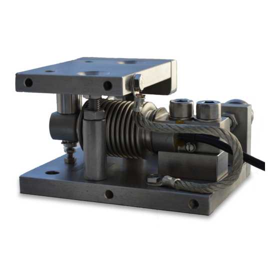
Description 3.2 Design • Welding work • Static charge The grounding cables in the compact installation units are made up of fine-core flexible copper wires. The flexible copper wires are tin-coated to additionally protect the copper from corrosion. Design 3.2.1 Compact mounting unit The compact installation unit comprises the following main components: ⑪... -
Page 14: Guide Element
Description 3.2 Design ① ⑧ Countersunk head screws Lower hexagon nut ② ⑨ Top plate Upper hexagon nut ③ ⑩ Bolts Washers ④ ⑪ Washers Pendulum bolt enclosure ⑤ ⑫ Load cell, not included in the scope of de‐ Pendulum bolt livery ⑥... -
Page 15: Nameplate
Description 3.3 Principle of operation Refer to the scope of delivery (Page 7) for the components. 3.2.3 Nameplate ① Product name ② Article number ③ Rated load ④ Manufacturer's address ⑤ Place of manufacture Figure 3-2 Example of nameplate Principle of operation 3.3.1 Compact mounting unit The top plate is aligned and fixed above the base plate with the two countersunk screws. - Page 16 Description 3.3 Principle of operation Figure 3-3 Pre-assembled compact mounting unit Prior to installation, the load cell is inserted with the pendulum bolt enclosure and the pendulum bolt into the compact mounting unit. The load cell is secured with 2 hexagon bolts in its position. Then the complete unit is installed in the scales.
-
Page 17: Guide Element
Description 3.3 Principle of operation Figure 3-5 Operating state In this state the load cell and the pressure pieces together form a self-centering unit. The compact mounting unit permits sideways displacement of the top plate, and hence of the load bearing implement, by up to 3 millimeters. - Page 18 Description 3.3 Principle of operation SB-S SA Equipment Manual, 12/2020, A5E02390707B-03...
-
Page 19: Application Planning
Application planning Load cell dummies Principle of operation Load cells are sensitive sensors. To protect the load cells from becoming damaged during installation and transport, install the load cells only at the last minute. Replace the load cells during installation and transport with placeholders, so-called dummies or phantoms. Dummies might be designed as follows: •... -
Page 20: Load Pick-Up
Application planning 4.3 Load pick-up Figure 4-1 Proposed solution for lifting protection Load pick-up Mounting surfaces The following requirements apply to the installation areas: • The positional and angular deviations of the mounting areas to each other correspond to the general tolerances for welded constructions in EN ISO 13920. -
Page 21: Overload Protection
Application planning 4.4 Overload protection Overload protection NOTICE Irreparable faults and damage to the load cells If load cells are used beyond the maximum working load or the maximum transverse load, this can cause irreparable faults and even fracturing of the load cell or the compact mounting unit. •... -
Page 22: Guide Elements
Application planning 4.5 Guide elements Guide elements Use the guide elements in the following cases: • A weight should be determined under the influence of transverse forces. • Horizontal movement of the load bearing implement should be prevented. A change in the distance between the support points, for example, as a result of expansion of the load bearing implement due to heat, must not lead to mutual tensioning of the guide elements. - Page 23 Application planning 4.5 Guide elements Three guide elements are sufficient to statically fix a weighing platform or container. Note Weighing errors With four guide elements, there is a risk of the guide elements mutually tensioning, which in turn induces weighing errors. If you nevertheless want to use four guide elements, the guide elements must be installed with a sufficient amount of play.
- Page 24 Application planning 4.5 Guide elements SB-S SA Equipment Manual, 12/2020, A5E02390707B-03...
-
Page 25: Installation
The load cell can be damaged when being handled improperly. Load cells are precision components. • Observe the operating instructions for the load cell. SIWAREX WL200 Operating instructions (https://support.industry.siemens.com/cs/ww/en/view/109749190) • Do not drop the load cell. • Protect the load cells from shocks. - Page 26 Installation 5.1 Safety information/instructions NOTICE Incorrect assembly of the load cell Damaging of load cells, installation parts or load bearing implement With load cells of smaller rated loads, there is a risk of stretching the load cell bodies when attaching force transfer devices, e.g. when tightening locknuts. Torsional and bending moments, eccentric loads and transverse loads are disturbance variables.
-
Page 27: Installing The Compact Installation Unit
Installation 5.2 Installing the compact installation unit NOTICE Improper installation of the load cell in the compact mounting unit An improper installation of the load cell in the compact mounting unit can destroy the load cell and the compact mounting unit. •... -
Page 28: Preparing The Load Cell
1. Keep the data sheet with the calibration values of the load cell. 2. Unpack the load cell. 3. Read the operating instructions of load cell. SIWAREX WL200 Operating instructions (https:// support.industry.siemens.com/cs/ww/en/view/109749190) 5.2.4 Preparing the compact installation unit Procedure 1. Unpack the compact mounting unit. - Page 29 Installation 5.2 Installing the compact installation unit Figure 5-1 Placing the pendulum bolt enclosure and the pendulum bolt into the load cell ① 1. Insert the pendulum bolt enclosure into the load cell. The arrow on the front of the load cell points in the measuring direction. ②...
-
Page 30: Installing The Compact Installation Unit
Installation 5.2 Installing the compact installation unit Result Figure 5-4 Installation state - Load cell installed in compact mounting unit As long as you do not loosen the hexagon nuts on the top plate, the compact mounting unit with the load cell is in the installation state. A distance of approximately 3 mm is set between the load and the load cell. - Page 31 Installation 5.2 Installing the compact installation unit 7. For all bracket plates to lie flat on the top plates, insert the compensation plates. 8. Tighten the bolted connections with the specified tightening torque (Page 39). Result ① Bracket plate ② Top plate ③...
-
Page 32: Lowering The Load Bearing Implement Onto The Load Cells
Installation 5.2 Installing the compact installation unit 5.2.7 Lowering the load bearing implement onto the load cells Procedure NOTICE Damaging the compact mounting unit When individual hexagon nuts are overloaded, the compact mounting unit can be damaged. By loosening a hexagon nut, the weight of the load bearing implement is distributed among the other hexagon nuts and is partially increased. -
Page 33: Checking The Installation
Use SIWAREX DB to determine which load cell has the lowest load. If you use SIWAREX DB, you do not need to disconnect SIG+ and SIG-. No multimeter is needed. SIWAREX DB Operating instructions (https://support.industry.siemens.com/cs/ww/en/ view/109779236) 2. Compensate for the differences in height: –... -
Page 34: Install Guide Element
Installation 5.3 Install guide element 1. Check the following items after the installation: – The load bearing implement swings freely. ① ② – The countersunk head screws are located in the center in the bores of the top plate The top plate has ideal freedom of movement and it prevents any incidental forces from occurring. -
Page 35: Preparing The Guide Element
Installation 5.3 Install guide element 5.3.2 Preparing the guide element Procedure 1. Unpack the guide element. 2. Check the Scope of delivery guide element (Page 7). 5.3.3 Locking the top plate Procedure • For a stable starting position, rotate the top hexagon nuts alternately up to the stop. 5.3.4 Fixing of guide element Procedure... -
Page 36: Fixing Of Second Guide Element
Installation 5.4 Dismantling 3. Rotate the top hexagon nuts downward. 4. To prevent the top hexagon nuts from turning upward in case of vibrations, fasten the top hexagon nuts against the lower hexagon nuts. Result All top plates are resting on the load cells by means of the pendulum bolt. The load cells are loaded. -
Page 37: Service And Maintenance
Service and maintenance Servicing and maintenance Important notes on cleaning NOTICE Damage to load cells, measurement errors Dirt must not be allowed to accumulate in the vicinity of a load cell. Do not subject cable glands, sealing elements and flat seals directly to the jet from a high- pressure hose. -
Page 38: Disposal
Service and maintenance 6.2 Disposal • Regularly check the existing overload protection elements: – Select the servicing intervals based on the occurrence of dust, dirt and moisture. – Keep the overload protection elements free of dirt and ice. – Check the settings for the overload protection elements. –... -
Page 39: Technical Data
Technical data Compact mounting unit Size At rated load At rated load 0.5 ... 2 t Maximum lateral deflection with load cell ± 3 mm ± 3 mm Lifting path of the top plate 3 mm 3 mm Restoring force per millimeter of lateral deflection 13% per mm 10% per mm of the top plate in % of the applied load with load... - Page 40 Technical data 7.2 Guide elements Material Guide element Stainless steel 1.4301 SB-S SA Equipment Manual, 12/2020, A5E02390707B-03...
-
Page 41: Dimension Drawings
Dimension drawings Compact mounting units • The compact mounting unit is supplied in the installation state. • The top plate is set 3 mm higher than in the operating state. The load cell is not loaded and protected against an overload due to the assembly. Figure 8-1 Installation state with installed load cell 0.5 to 2 t, dimensions in mm Figure 8-2... - Page 42 Dimension drawings 8.1 Compact mounting units Figure 8-3 Operating state with installed load cell and guide elements 0.5 to 2 t, dimensions in mm SB-S SA Equipment Manual, 12/2020, A5E02390707B-03...
- Page 43 Dimension drawings 8.1 Compact mounting units Figure 8-4 Operating state with installed load cell and guide elements 5 t, dimensions in mm SB-S SA Equipment Manual, 12/2020, A5E02390707B-03...
-
Page 44: Guide Elements
Dimension drawings 8.2 Guide elements Guide elements Figure 8-5 Guide elements 0.5 to 2 t, dimensions in mm Figure 8-6 Guide element 5 t, dimensions in mm SB-S SA Equipment Manual, 12/2020, A5E02390707B-03... -
Page 45: Ordering Data
Ordering data Accessories You can order accessories online: Industry Mall (https://mallstage.industry.siemens.com/ mall/en/b0/Catalog/Products/10289739?activeTab=Accessory) • Compensation plates for compensation of angle faults and unevenness against mounting plates. Material stainless steel 1.4301 SB-S SA Equipment Manual, 12/2020, A5E02390707B-03... - Page 46 Ordering data 9.1 Accessories SB-S SA Equipment Manual, 12/2020, A5E02390707B-03...
-
Page 47: Product Documentation And Support
Additional information on our technical support can be found at Technical Support (http:// www.siemens.com/automation/csi/service). Service & support on the Internet In addition to our technical support, Siemens offers comprehensive online services at Service & Support (http://www.siemens.com/automation/serviceandsupport). SB-S SA Equipment Manual, 12/2020, A5E02390707B-03... - Page 48 Product documentation and support A.2 Technical support Contact If you have further questions about the device, contact your local Siemens representative at Personal Contact (http://www.automation.siemens.com/partner). To find the contact for your product, go to "all products and branches" and select "Products &...
-
Page 49: Index
Index Hotline, (Refer to Support request) Application, 11 Installation Overview, 27 Preparing the guide element, 35 Catalog Technical data sheets, 47 Certificates, 9, 47 Cleaning, 37 Laws and directives Compact installation unit Disassembly, 9 Servicing and maintenance, 37 Personel, 9 Compact mounting unit Lifting protection, 19 Application, 11... - Page 50 Index Service and support Internet, 47 Structure Grounding cable, 13 Guide element, 15 Support, 47 Support point, 20 Support request, 47 Technical support, 47 partner, 48 personal contact, 48 Test certificates, 9 Warranty, 8 SB-S SA Equipment Manual, 12/2020, A5E02390707B-03...
Need help?
Do you have a question about the SIWAREX WL230 and is the answer not in the manual?
Questions and answers